
H3C S7500 Series Ethernet Switches Installation Manual

Installation Manual
H3C S7500 Series Ethernet Switches Chapter 1 Product Overview
1-18
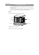
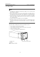
Note:
For the S7500 series, a board with pink edges can be inserted only into a slot indicated
by a pink area on the fan tray, and a board with purple or green edges can be inserted
only into a slot indicated by a purple area.
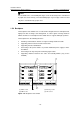
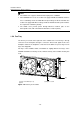
1.5.3 Backplane
The backplane of the S7500 series is located in the integrated chassis and implements
high-speed data exchange and management & control signal exchange between
SRPUs and LPUs. The backplane in the S7500 chassis supports XG high speed bus.
The backplane has the following functions:
z Providing communication channels for signal exchange between boards
z Supporting online insertion and removal of boards
z Supporting slot auto-identification
z Connecting to the power modules to provide distributed power supply for LPUs
and SRPUs
z Connecting to fan tray and power monitoring signal cables
z Supporting switchover between the active and standby SRPUs (only for the
S7506R)
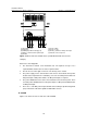
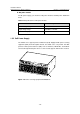
(1) (2)
(3)
(4)
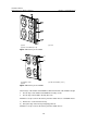
(1) SRPU socket (2) Fan tray socket
(3) PWR socket (4) LPU socket
Figure 1-11 Backplane of the S7503