
H3C S7500 Series Ethernet Switches Installation Manual

Installation Manual
H3C S7500 Series Ethernet Switches Appendix B N68 Cabinet Installation
B-42
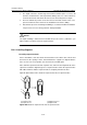
Caution:
You must insert the alignment rib of expansion nuts into the alignment grooves of
expansion tubes first; otherwise you will be unable to install or fasten the expansion
bolts.
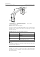
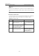
II. Adjusting the support height
To ensure that the upper surface of the guide rail is flush with that of the antistatic floor,
adjust all the supports to the prescribed heights before installing the supports.
Table B-8 Adjust support height
Step Operation Remarks
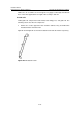
1
Measure the height of the upper
surface of the floor.
Deduct the height (50 mm: 2.0
in.) of the guide rail from this
value. You can get the support
height.
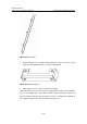
2
Adjust all the supports to the
prescribed heights according to the
silk-screen mark of the antistatic
floor height on the support.
—
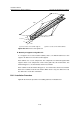
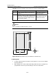
3 Torque the bolts to 45 Nm.
When fixing a support, fasten
the bolts in the middle first and
then those at the two sides, as
shown in
Figure B-41.