
H3C S7500 Series Ethernet Switches Installation Manual

Installation Manual
H3C S7500 Series Ethernet Switches Chapter 2 Line Processing Units
2-16
2.8.2 Panel and LEDs
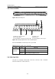
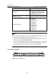
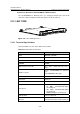
Figure 2-20 LS81GT48 panel
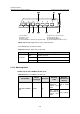
(1) Silkscreen of the LPU name (2) Captive screw
(3) LPU edge (purple) (4) Ejector lever
(5) 10/100/1000Base-T Ethernet port status LED (6) 10/100/1000Base-T Ethernet port
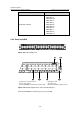
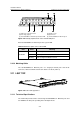
Figure 2-21 Partially amplified view of the LS81GT48 panel
Each 10/100/1000Base-T Ethernet port has a green LED.
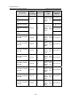
Table 2-15 LED description of the LS81GT48
LED Status Meaning
OFF
No link is present.
ON
A link is present.
LINK/ACT
Blinking
Data is being transmitted/received.
2.8.3 Matching Cable
The ports use category-5 twisted pairs and RJ-45 connectors, with a maximum
transmission distance of 100 m (328.1 ft).