H3C S7500 Series Ethernet Switches Operation Manual Hangzhou H3C Technologies Co., Ltd. http://www.h3c.com Manual Version: T2-08163Y-20070720-C-1.
Copyright © 2006-2007, Hangzhou H3C Technologies Co., Ltd. All Rights Reserved No part of this manual may be reproduced or transmitted in any form or by any means without prior written consent of Hangzhou H3C Technologies Co., Ltd. Trademarks H3C, , Aolynk, , H3Care, , TOP G, , IRF, NetPilot, Neocean, NeoVTL, SecPro, SecPoint, SecEngine, SecPath, Comware, Secware, Storware, NQA, VVG, V2G, VnG, PSPT, XGbus, N-Bus, TiGem, InnoVision and HUASAN are trademarks of Hangzhou H3C Technologies Co., Ltd.
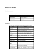
About This Manual Related Documentation In addition to this manual, each H3C S7500 Series Ethernet Switches documentation set includes the following: Manual Description H3C S7500 Series Ethernet Switches Command Manual It is used for assisting the users in using various commands. H3C S7500 Series Ethernet Switches Installation Manual It provides information for the system installation.
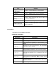
Part Contents 11 Port Isolation Introduces port isolation and the related configuration. 12 Port Binding Introduces port binding and the related configuration. 13 DLDP Introduces DLDP and the related configuration. 14 MAC Address Table Introduces MAC address forwarding table and the related configuration. 15 MSTP Introduces STP, VLAN-VPN tunnel and the related configurations. 16 Routing Protocol Introduces the routing protocol-related configurations.
Part Contents 37 System Maintenance and Debugging Introduces system maintenance and debugging. 38 HWPing Introduces HWPing and the related configuration. 39 RRPP Introduces RRPP and the related configuration. 40 NAT-Netstream-Policy Routing Introduces NAT, Netstream, policy-based routing, and the related configurations. 41 Telnet Protection Introduces Telnet securing and the related configuration. 42 Hardware-Dependent Software Configuration Introduces hardware-dependent related configuration.
II. GUI conventions Convention Description <> Button names are inside angle brackets. For example, click . [] Window names, menu items, data table and field names are inside square brackets. For example, pop up the [New User] window. / Multi-level menus are separated by forward slashes. For example, [File/Create/Folder]. III. Symbols Convention Description Warning Means reader be extremely careful. Improper operation may cause bodily injury. Caution Means reader be careful.
Operation Manual – Overview H3C S7500 Series Ethernet Switches Table of Contents Table of Contents Chapter 1 Documentation Obtaining........................................................................................... 1-1 1.1 CD-ROM ............................................................................................................................ 1-1 1.2 H3C Website...................................................................................................................... 1-1 1.
Operation Manual – Overview H3C S7500 Series Ethernet Switches Chapter 1 Documentation Obtaining Chapter 1 Documentation Obtaining Hangzhou H3C Technologies Co., Ltd. provides several ways for your convenience to obtain documentations (such as product and newly-added-feature documentations) in time. You can obtain documentations in the following ways: z CD-ROMs shipped with devices z H3C website z Software release notes 1.1 CD-ROM H3C delivers a CD-ROM together with each device.
Operation Manual – Overview H3C S7500 Series Ethernet Switches Chapter 2 Related Software Release Chapter 2 Related Software Release 2.1 Related Software Release The two manuals, H3C S7500 Series Ethernet Switches Operation Manual Release 3100 and H3C S7500 Series Ethernet Switches Command Manual Release 3100, are corresponding to the software Release 3135 of the S7500 series products. 2.
Operation Manual – Overview H3C S7500 Series Ethernet Switches Chapter 3 Product Overview Chapter 3 Product Overview 3.1 Introduction H3C S7500 Series Ethernet Switches (hereinafter referred to as the S7500 series) are a series of wire-speed Layer 2/3 Ethernet switching products with modular architecture and high-capacity.
Operation Manual – Overview H3C S7500 Series Ethernet Switches Chapter 3 Product Overview Table 3-2 Switching engines available to S7503/S7506/S7506R Engine model Available to… Salience III (LS81SRPG) S7503, S7506, S7506R Salience III Plus (LS81SRPG1) S7503, S7506, S7506R Salience III Edge (LS81SRPG3) S7503, S7506, S7506R Table 3-3 Switching engines available to S7502 Engine model Description LS81P12TE 4-port 10/100/1000Base-T + 12-port 1000Base-X (SFP) GE SRPU LS81T12PE 12-port 10/100/1000Ba
Operation Manual – Overview H3C S7500 Series Ethernet Switches Chapter 3 Product Overview Switching engine Salience III Salience III Plus Salience III Edge Service card LS82GT20 √ √ √ LS82GT20A √ √ √ LS81GT48 √ √ √ LS81GT48A √ √ √ LS81GT48B √ √ — LS81T12P √ √ √ LS81T12PE √ √ √ LS81T16P √ √ — LS81T32P √ √ — LS81P12T √ √ √ LS81P12TE √ √ √ LS81GP8UB √ — √ LS82GP20 √ √ √ LS82GP20A √ √ √ LS81GP48 √ √ — LS81TGX1C √ √ √ LS81TGX2 √ √ — LS81TGX
Operation Manual – Overview H3C S7500 Series Ethernet Switches Chapter 3 Product Overview Switching engine LS81T12 PE/ LS81P12 TE LS8 1T1 6P LS8 1T3 2P LS81 GT48 B LS81 GP4 8 LS81 TGX 2 LS81 TGX 4 LS81GT48 √ — — — — — — LS81GT48A √ — — — — — — LS81GT48B — √ √ √ √ √ √ LS81T12P √ — — — — — — LS81T12PE √ — — — — — — LS81T16P — √ √ √ √ √ √ LS81T32P — √ √ √ √ √ √ LS81P12T √ — — — — — — LS81P12TE √ — — — — — — LS81GP8UB √ — — —
Operation Manual – Overview H3C S7500 Series Ethernet Switches Chapter 3 Product Overview Engine Salience III Chassis [2] Salience III Plus Salience III Edge [2] S7506R √ √ √ S7506R XGbus √ √ √ [1] : When an Salience III series engine is used together with an S7503 chassis (with no XGbus silkscreen), you must use the product 7503 command in system view to identify the device as an S7503 switch and then restart the switch.
Operation Manual – Overview H3C S7500 Series Ethernet Switches Chapter 3 Product Overview Module Features supported z 09- Port Basic configuration z z z Three port states: access, trunk, hybrid Global broadcast suppression on ports Loopback detection Cable test 10-Link Aggregation LACP (link aggregation control protocol) 11-Port Isolation Port isolation group configuration 12-Port Binding MAC address-to-port binding 13-DLDP DLDP (device link detection protocol) z 14-MAC Address Table z z z
Operation Manual – Overview H3C S7500 Series Ethernet Switches Chapter 3 Product Overview Module Features supported z 22-ARP z z z z 23-DHCP z z z z z 24-ACL z z z 25-QoS z z z z 27-Cluster z z 28-PoE 29-UDP-Helper DHCP Server (DHCP: dynamic protocol) DHCP Relay DHCP Snooping Option 82 in DHCP Relay Option 82 in DHCP Snooping host configuration Basic ACL (access control list) Advance ACL Layer 2 ACL User-defined ACL QoS (quality of service) z 26-Mirroring Gratuitous ARP ARP source supp
Operation Manual – Overview H3C S7500 Series Ethernet Switches Chapter 3 Product Overview Module Features supported 38-HWPing HWPing 39-RRPP RRPP (rapid ring protection protocol) 40-NAT-Netstream -Policy Routing 41-Telnet Protection z z z Remote login protection z 42-Hardware-Depe ndent Software Configuration NAT (network address translation) NetStream policy routing z z z PoE DIMM (dual in-line memory module) memory card software upgrade Boot ROM upgrade by app file Inter-card link state adju
Operation Manual – Overview H3C S7500 Series Ethernet Switches Chapter 4 Networking Applications Chapter 4 Networking Applications The high-capacity, Layer 2/3 S7500 Series Ethernet Switches are mainly designed for IP MANs, large-sized enterprise networks and campus networks. They can serve as aggregation switches to play important role in MANs, or serve as core switches in enterprise or campus S3100/S3600/S5600/S9500 networks.
Operation Manual – Overview H3C S7500 Series Ethernet Switches Chapter 4 Networking Applications 4.2 Application in a Small/Medium-Sized Enterprise Network Typically, an S7500 series switch can be used at the backbone layer in a small/medium-sized enterprise network.
Operation Manual – Overview H3C S7500 Series Ethernet Switches Chapter 4 Networking Applications Figure 4-3 Application in a large-sized campus network 4.4 PoE Application Through the GE/FE electrical ports on a PoE-supported card, an S7500 series switch can supply power to PoE-supported PDs (powered devices, such as wireless WLAN APs, IP phones and corridor switches) across twisted pairs.
Operation Manual – CLI H3C S7500 Series Ethernet Switches Table of Contents Table of Contents Chapter 1 CLI Overview ................................................................................................................ 1-1 1.1 Introduction to the CLI ....................................................................................................... 1-1 1.2 Command Level/Command View ...................................................................................... 1-1 1.2.
Operation Manual – CLI H3C S7500 Series Ethernet Switches Chapter 1 CLI Overview Chapter 1 CLI Overview Go to these sections for information you are interested in: z Introduction to the CLI z Command Level/Command View z CLI Features 1.1 Introduction to the CLI H3C series Ethernet switches provide command line interfaces (CLI) and commands for you to configure and manage the Ethernet switches. The CLI features the following: z Commands are grouped by levels.
Operation Manual – CLI H3C S7500 Series Ethernet Switches Chapter 1 CLI Overview Users logging into a switch also fall into four levels, each of which corresponding to one of the above command levels. Users at a specific level can only use the commands of the same level and those of the lower levels. 1.2.1 Switching Between User Levels A user can switch the user level from one to another by executing a related command after logging into a switch.
Operation Manual – CLI H3C S7500 Series Ethernet Switches Chapter 1 CLI Overview 1.2.2 Configuring the Level of a Specific Command in a Specific View You can configure the level of a specific command in a specific view. Commands fall into four command levels: visit, monitor, system, and manage, which are identified as 0, 1, 2, and 3 respectively. The administrator can change the command level to which a command belongs.
Operation Manual – CLI H3C S7500 Series Ethernet Switches Chapter 1 CLI Overview z HWping view z Public key view z Public key code view z PIM view z RIP view z OSPF view z OSPF area view z BGP view z BGP IPv4 family multicast view z IS-IS view z ES-IS view z Routing policy view z Basic ACL view z Advanced ACL view z Layer 2 ACL view z User-defined ACL view z Traffic-group view z QoS view z QinQ view z RADIUS scheme view z HWTACACS scheme view z ISP domain view T
Operation Manual – CLI H3C S7500 Series Ethernet Switches View M-Ethernet interface view Chapter 1 CLI Overview Available operation Configure M-Ethernet interface parameters Prompt example [H3C-M-Ether net0/0/0] Enter method Quit method Manage Ethernet port view. Execute the quit command to return to system view. Execute the interface m-ethernet 0/0/0 command in system view. Execute the return command to return to user view.
Operation Manual – CLI H3C S7500 Series Ethernet Switches View VLAN view VLAN interface view Loopback interface view Local user view Chapter 1 CLI Overview Available operation Configure VLAN parameters Configure IP interface parameters for VLANs Configure Loopback interface parameters Configure local user parameters User interface view Configure user interface parameters FTP client view Configure FTP client parameters Prompt example [H3C-vlan1] [H3C-Vlan-int erface1] [H3C-LoopBa ck0] [H3
Operation Manual – CLI H3C S7500 Series Ethernet Switches View SFTP client view Cluster view DHCP address pool view MST region view RRPP domain view MSDP domain view Chapter 1 CLI Overview Available operation Configure SFTP client parameters Configure cluster parameters Configure DHCP address pool parameters Configure MST region parameters Configure RRPP domain parameters Configure MSDP domain parameters Prompt example sftp-client> [H3C-cluster] [H3C-dhcp-po ol-1] [H3C-mst-regi on] [H3Cr
Operation Manual – CLI H3C S7500 Series Ethernet Switches View Port-isolate-gr oup view Available operation Configure port-isolate-gr oup parameters HWping view Configure HWping test group parameters Public key view Configure RSA public keys for secure shell (SSH) users Public key code view Chapter 1 CLI Overview Edit RSA public keys of SSH users Prompt example [H3C-port-isol ate-group1] Enter method Execute the port-isolate group 1 command in system view.
Operation Manual – CLI H3C S7500 Series Ethernet Switches View RIP view OSPF view Available operation Configure RIP parameters Configure OSPF protocol parameters OSPF area view Configure OSPF area parameters BGP view Configure parameters for the border gateway protocol (BGP) protocol BGP IPv4 family multicast view Chapter 1 CLI Overview Configure parameters for BGP IPv4 family multicast Prompt example [H3C-rip] [H3C-ospf-1] [H3C-ospf-1-a rea-0.0.0.
Operation Manual – CLI H3C S7500 Series Ethernet Switches View IS-IS view ES-IS view Available operation Configure IS-IS parameters Configure parameters for the ES-IS protocol Routing policy view Configure routing policies Basic ACL view Define rules for a basic ACL (ACLs with their IDs ranging from 2000 to 2999 are basic ACLs.) Advanced ACL view Define rules for an advanced ACL (ACLs with their IDs ranging from 3000 to 3999 are advanced ACLs.
Operation Manual – CLI H3C S7500 Series Ethernet Switches View Available operation Layer 2 ACL view Define the sub-rules of Layer 2 ACLs, which is numbered from 4,000 to 4,999.
Operation Manual – CLI H3C S7500 Series Ethernet Switches View RADIUS scheme view HWTACACS scheme view ISP domain view Chapter 1 CLI Overview Available operation Configure RADIUS parameters Configure parameters for the HWTACACS protocol Configure parameters for an ISP domain Prompt example [H3C-radius-1 ] [H3C-hwtacac s-1] [H3C-isp-aabb cc.net] Enter method Execute the radius scheme 1 command in system view. Execute the hwtacacs scheme 1 command in system view. Execute the domain aabbcc.
Operation Manual – CLI H3C S7500 Series Ethernet Switches Chapter 1 CLI Overview clock Specify the system clock cluster Run cluster command copy Copy from one file to another debugging Enable system debugging functions delete Delete a file dir List files on a file system display Display current system information 2) Enter a command, a space, and a ? character (instead of a keyword available in this position of the command) on your terminal to display all the available keywords an
Operation Manual – CLI H3C S7500 Series Ethernet Switches Chapter 1 CLI Overview You can use the language-mode command to translate the help into Chinese. 1.3.2 Terminal Display CLI provides the following display features: z The online help and prompt information can be displayed in either Chinese or English. z Display suspending, that is, the displaying of output information can be paused when the screen is full and you can then perform the three operations listed in Table 1-2 as needed.
Operation Manual – CLI H3C S7500 Series Ethernet Switches Chapter 1 CLI Overview Note: z As the Up and Down keys have different meanings in HyperTerminal running on Windows 9x, these two keys can be used to recall history commands only in terminals running Windows 3.x or Telnet running in Windows 3.x. You can press or in Windows 9x to achieve the same purpose.
Operation Manual – CLI H3C S7500 Series Ethernet Switches Chapter 1 CLI Overview Press… To… The Backspace key Delete the character on the left of the cursor and move the cursor one character to the left. The left arrow key or Move the cursor one character to the left. The right arrow key or Move the cursor one character to the right. The up arrow key or The down arrow key or The Tab key Access history commands. Utilize the partial online help.
Operation Manual – Login H3C S7500 Series Ethernet Switches Table of Contents Table of Contents Chapter 1 Logging into an Ethernet Switch ............................................................................... 1-1 1.1 Logging into an Ethernet Switch ........................................................................................ 1-1 1.2 Introduction to the User Interface ...................................................................................... 1-1 1.2.
Operation Manual – Login H3C S7500 Series Ethernet Switches Table of Contents Chapter 4 Logging in Using Modem............................................................................................ 4-1 4.1 Introduction ........................................................................................................................ 4-1 4.2 Configuration on the Administrator Side............................................................................ 4-1 4.3 Configuration on the Switch Side.
Operation Manual – Login H3C S7500 Series Ethernet Switches Chapter 1 Logging into an Ethernet Switch Chapter 1 Logging into an Ethernet Switch When configuring logging into an Ethernet switch, go to these sections for information you are interested in: z Logging into an Ethernet Switch z Introduction to the User Interface 1.
Operation Manual – Login H3C S7500 Series Ethernet Switches Chapter 1 Logging into an Ethernet Switch 1) The absolute user interface indexes are as follows: z AUX user interface: 0 z VTY user interfaces: Numbered after the AUX user interface.
Operation Manual – Login H3C S7500 Series Ethernet Switches Chapter 1 Logging into an Ethernet Switch Caution: z The auto-execute command command may cause you unable to perform common configuration in the user interface, so use it with caution. z Before configuring the auto-execute command command and saving the configuration, make sure you can log into the switch in other ways to cancel the configuration.
Operation Manual – Login H3C S7500 Series Ethernet Switches Chapter 2 Logging in through the Console Port Chapter 2 Logging in through the Console Port When logging into a switch through its console port, go to these sections for information you are interested in: z Introduction z Logging in through the Console Port z Console Port Login Configuration z Console Port Login Configuration with Authentication Mode Being None z Console Port Login Configuration with Authentication Mode Being Password z
Operation Manual – Login H3C S7500 Series Ethernet Switches RS-232 Chapter 2 Logging in through the Console Port Console port Configuration cable PC Switch Figure 2-1 Diagram for setting the connection to the console port 2) If you use a PC to connect to the console port, launch a terminal emulation program (such as Terminal in Windows 3.
Operation Manual – Login H3C S7500 Series Ethernet Switches Chapter 2 Logging in through the Console Port Figure 2-4 Set port parameters 3) Power on the switch. You will be prompted to press the Enter key if the switch successfully completes POST (power-on self test). The prompt (such as ) appears after you press the Enter key. 4) You can then configure the switch or check the information about the switch by executing the corresponding commands. You can also acquire help by type the ? character.
Operation Manual – Login H3C S7500 Series Ethernet Switches Chapter 2 Logging in through the Console Port Table 2-2 Common configuration of console port login Configuration Baud rate Remarks Optional The default baud rate is 9,600 bps.
Operation Manual – Login H3C S7500 Series Ethernet Switches Chapter 2 Logging in through the Console Port 2.3.2 Console Port Login Configurations for Different Authentication Modes Table 2-3 lists console port login configurations for different authentication modes.
Operation Manual – Login H3C S7500 Series Ethernet Switches Chapter 2 Logging in through the Console Port 2.4 Console Port Login Configuration with Authentication Mode Being None 2.4.
Operation Manual – Login H3C S7500 Series Ethernet Switches To do… Chapter 2 Logging in through the Console Port Use the command… Remarks Optional By default, the screen can contain up to 24 lines. Set the maximum number of lines the screen can contain screen-length screen-length You can use the screen-length 0 command to disable the function of displaying information in pages.
Operation Manual – Login H3C S7500 Series Ethernet Switches Chapter 2 Logging in through the Console Port Table 2-4 Determine the command level Scenario Authentication mode None (authenticationmode none) User type Command configuration Users logging in through console ports Command level The user privilege level level command is not executed Level 3 The user privilege level level command is already executed Determined by the level argument 2.4.2 Configuration Example I.
Operation Manual – Login H3C S7500 Series Ethernet Switches Chapter 2 Logging in through the Console Port # Enter AUX user interface view. [H3C] user-interface aux 0 # Specify not to authenticate users logging in through the console port. [H3C-ui-aux0] authentication-mode none # Specify commands of level 2 are available to users logging into the AUX user interface. [H3C-ui-aux0] user privilege level 2 # Set the baud rate of the console port to 19,200 bps.
Operation Manual – Login H3C S7500 Series Ethernet Switches To do… Chapter 2 Logging in through the Console Port Use the command… Remarks Optional Configur e the console port Set the baud rate speed speed-value Set the check mode parity { even | mark | none | odd | space } By default, the check mode of a console port is set to none, that is, no check bit. Set the flow control mode flow-control { hardware | none | software } Optional Set the stop bits stopbits { 1 | 1.
Operation Manual – Login H3C S7500 Series Ethernet Switches Chapter 2 Logging in through the Console Port To do… Use the command… Remarks Optional The default timeout time of a user interface is 10 minutes. Set the timeout time for the user interface idle-timeout minutes [ seconds ] With the timeout time being 10 minutes, the connection to a user interface is terminated if no operation is performed in the user interface within 10 minutes.
Operation Manual – Login H3C S7500 Series Ethernet Switches Chapter 2 Logging in through the Console Port II. Network diagram Ethernet1/0/1 Ethernet User PC running Telnet Figure 2-6 Network diagram for AUX user interface configuration (with the authentication mode being password) III. Configuration procedure # Enter system view. system-view # Enter AUX user interface view. [H3C] user-interface aux 0 # Specify to authenticate users logging in through the console port using the local password.
Operation Manual – Login H3C S7500 Series Ethernet Switches Chapter 2 Logging in through the Console Port 2.6 Console Port Login Configuration with Authentication Mode Being Scheme 2.6.
Operation Manual – Login H3C S7500 Series Ethernet Switches To do… Chapter 2 Logging in through the Console Port Use the command… Remarks Required Configure to authenticate users locally or remotely using user name and password authentication-mode scheme [ commandauthorization ] The specified AAA scheme determines whether to authenticate users locally or remotely. Users are authenticated locally by default.
Operation Manual – Login H3C S7500 Series Ethernet Switches Chapter 2 Logging in through the Console Port To do… Use the command… Remarks Optional Set history command buffer size history-command max-size value The default history command buffer size is 10. That is, a history command buffer can store up to 10 commands by default. Optional The default timeout time of a user interface is 10 minutes.
Operation Manual – Login H3C S7500 Series Ethernet Switches Chapter 2 Logging in through the Console Port z Set the service type of the local user to Terminal. z Configure to authenticate users logging in through the console port in the scheme mode. z The commands of level 2 are available to users logging into the AUX user interface. z The baud rate of the console port is 19,200 bps. z The screen can contain up to 30 lines. z The history command buffer can store up to 20 commands.
Operation Manual – Login H3C S7500 Series Ethernet Switches Chapter 2 Logging in through the Console Port # Set the baud rate of the console port to 19,200 bps. [H3C-ui-aux0] speed 19200 # Set the maximum number of lines the screen can contain to 30. [H3C-ui-aux0] screen-length 30 # Set the maximum number of commands the history command buffer can store to 20. [H3C-ui-aux0] history-command max-size 20 # Set the timeout time of the AUX user interface to 6 minutes.
Operation Manual – Login H3C S7500 Series Ethernet Switches Chapter 3 Logging in through Telnet Chapter 3 Logging in through Telnet When logging into a switch through Telnet, go to these sections for information you are interested in: z Introduction z Telnet Configuration with Authentication Mode Being None z Telnet Configuration with Authentication Mode Being Password z Telnet Configuration with Authentication Mode Being Scheme z Telneting to a Switch 3.
Operation Manual – Login H3C S7500 Series Ethernet Switches Chapter 3 Logging in through Telnet Configuration Description Make terminal services available VTY terminal configuration Set the maximum number of lines the screen can contain Optional By default, terminal services are available in all user interfaces Optional By default, the screen can contain up to 24 lines. Optional Set history command buffer size By default, the history command buffer can contain up to 10 commands.
Operation Manual – Login H3C S7500 Series Ethernet Switches Authentication mode Chapter 3 Logging in through Telnet Telnet configuration Description Optional AAA configuration specifies whether to perform local authentication or RADIUS authentication Specify to perform local authentication or RADIUS authentication Local authentication is performed by default. Refer to the AAA&RADIUS&HWTACA CS&EAD module for more.
Operation Manual – Login H3C S7500 Series Ethernet Switches To do… Chapter 3 Logging in through Telnet Use the command… Remarks Optional Configure the command level available to users logging into VTY user interface user privilege level level Configure the protocols to be supported by the VTY user interface protocol inbound { all | ssh | telnet } By default, commands of level 0 are available to users logging into VTY user interfaces.
Operation Manual – Login H3C S7500 Series Ethernet Switches Chapter 3 Logging in through Telnet Table 3-4 Determine the command level when users logging into switches are not authenticated Scenario Authentication mode User type None (authentication -mode none) Command configuration Command level The user privilege level level command is not executed Level 0 The user privilege level level command is already executed Determined by the level argument VTY users 3.2.2 Configuration Example I.
Operation Manual – Login H3C S7500 Series Ethernet Switches Chapter 3 Logging in through Telnet [H3C-ui-vty0] user privilege level 2 # Configure Telnet protocol is supported. [H3C-ui-vty0] protocol inbound telnet # Set the maximum number of lines the screen can contain to 30. [H3C-ui-vty0] screen-length 30 # Set the maximum number of commands the history command buffer can store to 20. [H3C-ui-vty0] history-command max-size 20 # Set the timeout time to 6 minutes. [H3C-ui-vty0] idle-timeout 6 3.
Operation Manual – Login H3C S7500 Series Ethernet Switches To do… Chapter 3 Logging in through Telnet Use the command… Remarks Optional Set the maximum number of lines the screen can contain By default, the screen can contain up to 24 lines. screen-length screen-length You can use the screen-length 0 command to disable the function of displaying information in pages. Optional Set the history command buffer size history-command max-size value The default history command buffer size is 10.
Operation Manual – Login H3C S7500 Series Ethernet Switches Chapter 3 Logging in through Telnet Table 3-5 Determine the command level when users logging into switches are authenticated in the password mode Scenario Authentication mode Password (authenticationmode password) User type Command configuration Command level The user privilege level level command is not executed Level 0 The user privilege level level command is already executed Determined by the level argument VTY users 3.3.
Operation Manual – Login H3C S7500 Series Ethernet Switches Chapter 3 Logging in through Telnet # Set the password to 123456 (in plain text). [H3C-ui-vty0] set authentication password simple 123456 # Specify commands of level 2 are available to users logging into VTY 0. [H3C-ui-vty0] user privilege level 2 # Configure Telnet protocol is supported. [H3C-ui-vty0] protocol inbound telnet # Set the maximum number of lines the screen can contain to 30.
Operation Manual – Login H3C S7500 Series Ethernet Switches To do… Enter system view Configure the authentic ation scheme Chapter 3 Logging in through Telnet Use the command… system-view Remarks — Optional Enter the default ISP domain view domain domain-name Configure the AAA scheme to be applied to the domain scheme { local | radius-scheme radius-scheme-name [ local ] | none } By default, the local AAA scheme is applied.
Operation Manual – Login H3C S7500 Series Ethernet Switches Chapter 3 Logging in through Telnet To do… Use the command… Configure the supported protocol protocol inbound { all | ssh | telnet } Make terminal services available shell Remarks Optional Both Telnet protocol and SSH protocol are supported by default. Optional Terminal services are available in all user interfaces by default.
Operation Manual – Login H3C S7500 Series Ethernet Switches Chapter 3 Logging in through Telnet Table 3-6 Determine the command level when users logging into switches are authenticated in the scheme mode Scenario Authenticati on mode User type VTY users that are AAA&RAD IUS authentica ted or locally authentica ted Scheme (authenticati on-mode scheme) [ command-a uthorization ] Command configuration Command level The user privilege level level command is not executed, and the service-type command doe
Operation Manual – Login H3C S7500 Series Ethernet Switches Chapter 3 Logging in through Telnet Scenario Authenticati on mode User type Command level Command configuration The user privilege level level command is executed, and the service-type command does not specify the available command level. Level 0 The user privilege level level command is executed, and the service-type command specifies the available command level.
Operation Manual – Login H3C S7500 Series Ethernet Switches Chapter 3 Logging in through Telnet III. Configuration procedure # Enter system view. system-view # Create a local user named guest and enter local user view. [H3C] local-user guest # Set the authentication password of the local user to 123456 (in plain text). [H3C-luser-guest] password simple 123456 # Set the service type to Telnet, with the user level being 2.
Operation Manual – Login H3C S7500 Series Ethernet Switches z Chapter 3 Logging in through Telnet Launch a terminal emulation program (such as Terminal in Windows 3.X or HyperTerminal in Windows 9X) on the PC, with the baud rate set to 9,600 bps, data bits set to 8, parity check set to none, and flow control set to none. z Power on the switch and press Enter as prompted. The prompt (such as ) appears.
Operation Manual – Login H3C S7500 Series Ethernet Switches Chapter 3 Logging in through Telnet Figure 3-6 Launch Telnet 5) Enter the password when the Telnet window displays “Login authentication” and prompts for login password. The CLI prompt (such as ) appears if the password is correct. If all VTY user interfaces of the switch are in use, you will fail to establish the connection and receive the message that says “All user interfaces are used, please try later!”.
Operation Manual – Login H3C S7500 Series Ethernet Switches PC Chapter 3 Logging in through Telnet Telnet Client Telnet Server Figure 3-7 Network diagram for Telneting to another switch from the current switch 1) Perform Telnet-related configuration on the switch operating as the Telnet server.
Operation Manual – Login H3C S7500 Series Ethernet Switches Chapter 4 Logging in Using Modem Chapter 4 Logging in Using Modem When logging into a switch using a Modem, go to these sections for information you are interested in: z Introduction z Configuration on the Administrator Side z Configuration on the Switch Side z Modem Connection Establishment z Modem Attributes Configuration 4.
Operation Manual – Login H3C S7500 Series Ethernet Switches Chapter 4 Logging in Using Modem 4.3 Configuration on the Switch Side 4.3.
Operation Manual – Login H3C S7500 Series Ethernet Switches Chapter 4 Logging in Using Modem I. Configuration on switch when the authentication mode is none Refer to section Console Port Login Configuration with Authentication Mode Being None. II. Configuration on switch when the authentication mode is password Refer to section Console Port Login Configuration with Authentication Mode Being Password. III.
Operation Manual – Login H3C S7500 Series Ethernet Switches Chapter 4 Logging in Using Modem Modem serial cable Telephone line Modem PSTN Modem Telephone number of the romote end: 82882285 Console port Figure 4-1 Establish the connection by using Modems 4) Launch a terminal emulation program on the PC and set the telephone number to call the Modem directly connected to the switch, as shown in Figure 4-2 and Figure 4-3.
Operation Manual – Login H3C S7500 Series Ethernet Switches Chapter 4 Logging in Using Modem Figure 4-3 Call the Modem 5) Provide the password on the emulation grogram when prompted. If the password is correct, the prompt (such as ) appears. You can then configure or manage the switch. You can also enter the character ? at anytime for help. Refer to the following chapters for information about the configuration commands.
Operation Manual – Login H3C S7500 Series Ethernet Switches Chapter 4 Logging in Using Modem To do… Use the command… Remarks Enter system view system-view — Enter AUX user interface view user-interface aux 0 — Required Enable Modem call-in/call-in and call-out modem [ call-in | both ] Call-in and call-out are allowed when the command is executed without any keyword. Optional Set the answer mode to auto answer. modem auto-answer By default, manual answer mode is adopted.
Operation Manual – Login H3C S7500 Series Ethernet Switches Chapter 5 Logging in through NMS Chapter 5 Logging in through NMS When logging into a switch through NMS, go to these sections for information you are interested in: z Introduction z Connection Establishment Using NMS 5.1 Introduction You can also log into a switch through a network management station (NMS ), and then configure and manage the switch through the agent module on the switch. z NMS: network management station.
Operation Manual – Login H3C S7500 Series Ethernet Switches Chapter 5 Logging in through NMS 5.
Operation Manual – Login H3C S7500 Series Ethernet Switches Chapter 6 User Control Chapter 6 User Control When configuring user control, go to these sections for information you are interested in: z Introduction z Controlling Telnet Users z Controlling Network Management Users by Source IP Addresses 6.1 Introduction A switch provides ways to control different types of login users, as listed in Table 6-1.
Operation Manual – Login H3C S7500 Series Ethernet Switches To do… Chapter 6 User Control Use the command… Remarks Enter system view system-view — Create a basic ACL or enter basic ACL view acl { number acl-number | name acl-name [ advanced | basic | link | user ] } [ match-order { config | auto } ] As for the acl number command, the config keyword is specified by default.
Operation Manual – Login H3C S7500 Series Ethernet Switches To do… Chapter 6 User Control Use the command… Remarks Define rules for the ACL rule [ rule-id ] { permit | deny } protocol [ source { source-addr wildcard | any } ] [ destination { dest-addr dest-mask | any } ] [ source-port operator port1 [ port2 ] ] [ destination-port operator port1 [ port2 ] ] [ icmp-type type code ] [ established ] [ [ precedence precedence | tos tos ]* | dscp dscp ] [ fragment ] [ time-range time-name ] Return to syste
Operation Manual – Login H3C S7500 Series Ethernet Switches Chapter 6 User Control 6.3.2 Controlling Network Management Users by Source IP Addresses Controlling network management users by source IP addresses is achieved by applying basic ACLs, which are numbered from 2000 to 2999.
Operation Manual – Login H3C S7500 Series Ethernet Switches Chapter 6 User Control Note: You can specify different ACLs while configuring the SNMP community name, the SNMP group name, and the SNMP user name. As SNMP community name is a feature of SNMPv1 and SNMPv2c, the specified ACLs in the command that configures SNMP community names (the snmp-agent community command) take effect in the network management systems that adopt SNMPv1 or SNMPv2c.
Operation Manual – Login H3C S7500 Series Ethernet Switches Chapter 6 User Control # Apply the ACL to only permit SNMP users sourced from the IP addresses of 10.110.100.52 and 10.110.100.46 to access the switch.
Operation Manual – Configuration File Management H3C S7500 Series Ethernet Switches Table of Contents Table of Contents Chapter 1 Configuration File Management ................................................................................. 1-1 1.1 Introduction to Configuration File....................................................................................... 1-1 1.2 Configuration File-Related Operations ..............................................................................
Operation Manual – Configuration File Management H3C S7500 Series Ethernet Switches Chapter 1 Configuration File Management Chapter 1 Configuration File Management When configuring configuration file management, go to these sections for information you are interested in: z Introduction to Configuration File z Configuration File-Related Operations 1.1 Introduction to Configuration File Configuration files record and store configurations performed to an Ethernet switch.
Operation Manual – Configuration File Management H3C S7500 Series Ethernet Switches Chapter 1 Configuration File Management To do… Use the command… Remarks Save the current configuration into the Flash save [ file-name | safely ] Optional Remove a specific configuration file from the Flash reset saved-configuration Optional Specify the configuration file to be used in the next startup startup saved-configuration { cfgfile | device-name } Optional Display the primary configuration file display
Operation Manual – Configuration File Management H3C S7500 Series Ethernet Switches z Chapter 1 Configuration File Management Safely saving mode: if the safely keyword is provided, the system saves the configuration files in the safely saving mode. In this mode, the configuration files are saved slowly. However, even if restart or power-off occurs in the saving procedure, the configuration files will be saved in the Flash.
Operation Manual – VLAN H3C S7500 Series Ethernet Switches Table of Contents Table of Contents Chapter 1 VLAN Overview ............................................................................................................ 1-1 1.1 VLAN Overview.................................................................................................................. 1-1 1.1.1 Introduction to VLAN ............................................................................................... 1-1 1.1.
Operation Manual – VLAN H3C S7500 Series Ethernet Switches Chapter 1 VLAN Overview Chapter 1 VLAN Overview This chapter covers the following topics: z VLAN Overview z Port-Based VLAN z Protocol-Based VLAN 1.1 VLAN Overview 1.1.1 Introduction to VLAN The traditional Ethernet is a flat network, where all hosts are in the same broadcast domain and connected with each other through hubs or switches.
Operation Manual – VLAN H3C S7500 Series Ethernet Switches Chapter 1 VLAN Overview Router Switch VLAN A Switch VLANB VLAN A VLAN A VLANB VLAN B Figure 1-1 A VLAN implementation A VLAN can span across multiple switches, or even routers. This enables hosts in a VLAN to be dispersed in a looser way. That is, hosts in a VLAN can belong to different physical network segment. Compared with the traditional Ethernet, VLAN enjoys the following advantages. 1) Broadcasts are confined to VLANs.
Operation Manual – VLAN H3C S7500 Series Ethernet Switches DA&SA Chapter 1 VLAN Overview Type Data Figure 1-2 Encapsulation format of traditional Ethernet frames In Figure 1-2 DA refers to the destination MAC address, SA refers to the source MAC address, and Type refers to the protocol type of the packet. IEEE 802.1Q protocol defines that a 4-byte VLAN tag is encapsulated after the destination MAC address and source MAC address to show the information about VLAN.
Operation Manual – VLAN H3C S7500 Series Ethernet Switches Chapter 1 VLAN Overview 1.2.1 Link Types of Ethernet Ports An Ethernet port on an S7500 switch can operate in one of the three link types: z Access: An Access port can belong to only one VLAN, and is generally used to connect user PCs. z Trunk: A Trunk port can belong to more than one VLAN. It can receive/send packets from/to multiple VLANs, and is generally used to connect another switch.
Operation Manual – VLAN H3C S7500 Series Ethernet Switches Chapter 1 VLAN Overview Caution: You are recommended to set the default VLAN ID of the local Hybrid or Trunk ports to the same value as that of the Hybrid or Trunk ports on the peer switch. Otherwise, packet forwarding may fail on the ports. After a port is added to a VLAN and configured with a default VLAN, the port receives and sends packets in a way related to its link type.
Operation Manual – VLAN H3C S7500 Series Ethernet Switches Chapter 1 VLAN Overview Table 1-3 Packet processing of a Hybrid port Processing of an incoming packet If the packet does not carry a VLAN tag z z If the port is already added to its default VLAN, add the default VLAN tag to the packet and then forward the packet. If the port is not added to its default VLAN, discard the packet.
Operation Manual – VLAN H3C S7500 Series Ethernet Switches DA&SA(12) Length(2) Chapter 1 VLAN Overview DSAP(1) SSAP(1) Control(1) OUI(3) PID(2) Data Figure 1-5 802.2/802.3 encapsulation format In the two figures, DA and SA refer to the destination MAC address and source MAC address of the packet respectively. The number in the brackets indicates the field length in bits. The maximum length of an Ethernet packet is 1500 bytes, that is, 5DC in hexadecimal, so the length field in 802.2/802.
Operation Manual – VLAN H3C S7500 Series Ethernet Switches DA&SA(12) Chapter 1 VLAN Overview Length(2) DSAP(1) SSAP(1) Control(1) OUI(3) PID(2) Data Figure 1-8 802.2 SNAP encapsulation format In 802.2 SNAP encapsulation format, the values of the DSAP field and the SSAP field are always AA, and the value of the control field is always 3. The switch differentiates between 802.2 LLC encapsulation and 802.2 SNAP encapsulation according to the values of the DSAP field and the SSAP field.
Operation Manual – VLAN H3C S7500 Series Ethernet Switches Chapter 1 VLAN Overview 1.3.4 Encapsulation Formats Table 1-4 Encapsulation formats Encap Ethernet II 802.3 raw 802.2 SNAP 802.2 LLC Type value Protocol IP Supported Not supported Not supported Supported 0x0800 IPX Supported Supported Supported Supported 0x8137 AppleTalk Supported Not supported Not supported Supported 0x809B 1.3.
Operation Manual – VLAN H3C S7500 Series Ethernet Switches Chapter 2 VLAN Configuration Chapter 2 VLAN Configuration When configuring VLAN, go to these sections for information you are interested in: z VLAN Configuration z Configuring a Port-Based VLAN z Configuring a Protocol-Based VLAN 2.1 VLAN Configuration 2.1.
Operation Manual – VLAN H3C S7500 Series Ethernet Switches Chapter 2 VLAN Configuration To do… Set VLAN broadcast storm suppression Use the command… Remarks broadcast-suppression { ratio | pps pps } Required A VLAN only supports one broadcast storm suppression mode at one time. If you configure broadcast storm suppression modes multiple times for a VLAN, the latest configuration will overwrite the previous configuration.
Operation Manual – VLAN H3C S7500 Series Ethernet Switches Chapter 2 VLAN Configuration To do… Use the command… Remarks Disable the VLAN interface shutdown Optional Enable the VLAN Interface undo shutdown Optional Note that the operation of enabling/disabling a VLAN interface does not influence the enabling/disabling status of the Ethernet ports belonging to this VLAN. By default, a VLAN interface is enabled.
Operation Manual – VLAN H3C S7500 Series Ethernet Switches Chapter 2 VLAN Configuration Follow these steps to configure the Access-port-based VLAN in Ethernet port view: To do… Use the command… Remarks Enter system view system-view — Enter Ethernet port view interface interface-type interface-number — Configure the port link type as Access port link-type access Add the current Access port to a specified VLAN port access vlan vlan-id Optional The link type of a port is Access by default.
Operation Manual – VLAN H3C S7500 Series Ethernet Switches Chapter 2 VLAN Configuration Note: z To convert a Trunk port into a Hybrid port (or vice versa), you need to use the Access port as a medium. For example, the Trunk port has to be configured as an Access port first and then a Hybrid port. z The default VLAN IDs of the Trunk ports on the local and peer devices must be the same. Otherwise, packets cannot be transmitted properly. 2.2.
Operation Manual – VLAN H3C S7500 Series Ethernet Switches Chapter 2 VLAN Configuration 2.2.4 Protocol-based VLAN Configuration Example I. Configuration requirements z Create VLAN 2 and VLAN 3 and specify the description string of VLAN 2 as home; z Add Ethernet 2/0/1 and Ethernet 2/0/2 to VLAN 2 and add Ethernet 2/0/3 and Ethernet 2/0/4 to VLAN 3. II. Network diagram Eth2/0/1 Eth2 /0/3 Eth2/0 /2 Eth2/0/4 VLAN 3 VLAN2 Figure 2-1 Network diagram for VLAN configuration III.
Operation Manual – VLAN H3C S7500 Series Ethernet Switches Chapter 2 VLAN Configuration To do… Use the command… Create the protocol template for the VLAN protocol-vlan [ protocol-index ] { at | ip [ ip-address [ net-mask ] ] | ipx { ethernetii | llc | raw | snap } | mode { ethernetii [ etype etype-id ] | llc [ dsap dsap-id [ ssap ssap-id ] | ssap ssap-id ] | snap [ etype etype-id ] } } Remarks Required When you are creating protocol templates for protocol-based VLANs, the at, ip and ipx keywords are
Operation Manual – VLAN H3C S7500 Series Ethernet Switches Chapter 2 VLAN Configuration 2.3.2 Associating a Port with the Protocol-Based VLAN I. Configuration prerequisites z The protocol template for the protocol-based VLAN is created z The port is configured as a Hybrid port, and the port is configured to remove VLAN tags when it forwards the packets of the protocol-based VLANs. II.
Operation Manual – VLAN H3C S7500 Series Ethernet Switches To do… Chapter 2 VLAN Configuration Use the command… Remarks Enter system view system-view — Create protocol-based VLAN on specific card protocol-vlan vlan vlan-id { protocol-index [ to protocol-end ] | all } { slot slot-number | mainboard } Required Caution: z It is necessary to add those ports that require protocol on the card to the protocol-based VLAN.
Operation Manual – VLAN H3C S7500 Series Ethernet Switches Chapter 2 VLAN Configuration 2.3.
Operation Manual – VLAN H3C S7500 Series Ethernet Switches Chapter 2 VLAN Configuration # Associate the port with protocol-index 1. [H3C-Ethernet2/0/5] port hybrid protocol-vlan vlan 5 1 II. User-defined-template-based protocol VLAN configuration example 1) Network requirement z Create VLAN 7 and configure it as a protocol-based VLAN. z Create two indexes in VLAN 7. Index 1 is used to match the packets with DSAP and SSAP value being 01 and ac respectively in 802.
Operation Manual – Extended VLAN Application H3C S7500 Series Ethernet Switches Table of Contents Table of Contents Chapter 1 Voice VLAN Configuration.......................................................................................... 1-1 1.1 Voice VLAN Overview ....................................................................................................... 1-1 1.2 Voice VLAN Configuration ................................................................................................. 1-4 1.
Operation Manual – Extended VLAN Application H3C S7500 Series Ethernet Switches Table of Contents ii
Operation Manual – Extended VLAN Application H3C S7500 Series Ethernet Switches Chapter 1 Voice VLAN Configuration Chapter 1 Voice VLAN Configuration When configuring voice VLAN, go to these sections for information you are interested in: z Voice VLAN Overview z Voice VLAN Configuration z Displaying Voice VLAN Configuration z Voice VLAN Configuration Examples 1.1 Voice VLAN Overview Voice VLANs are VLANs configured specially for voice data stream.
Operation Manual – Extended VLAN Application H3C S7500 Series Ethernet Switches Number Chapter 1 Voice VLAN Configuration OUI Address Vendor 4 00d0-1e00-0000 Pingtel phone 5 000f-e200-0000 H3C Aolynk phone There are two voice VLAN modes on a port: automatic and manual. You can configure the voice VLAN mode of a port according to data stream passing through the port.
Operation Manual – Extended VLAN Application H3C S7500 Series Ethernet Switches Chapter 1 Voice VLAN Configuration Table 1-2 Matching relationship between port modes and voice stream types Port voice VLAN mode Voice stream type Port type Access Supported or not Not supported Supported Trunk Tagged voice stream Make sure the default VLAN of the IP phone access port exists and is not the voice VLAN. And the IP phone access port permits the packets of the default VLAN to pass.
Operation Manual – Extended VLAN Application H3C S7500 Series Ethernet Switches Chapter 1 Voice VLAN Configuration Caution: z If the voice traffic sent by an IP voice device is tagged and the access port has 802.1x authentication and guest VLAN enabled, assign different VLAN IDs for the voice VLAN, the default VLAN of the access port, and the 802.1x guest VLAN.
Operation Manual – Extended VLAN Application H3C S7500 Series Ethernet Switches To do… Chapter 1 Voice VLAN Configuration Use the command… Remarks Optional Enable the voice VLAN security mode voice vlan security enable Set the aging time for the voice VLAN voice vlan aging minutes The default aging time is 1,440 minutes. Enable the voice VLAN function globally voice vlan vlan-id enable Required By default, the voice VLAN security mode on the port is enabled.
Operation Manual – Extended VLAN Application H3C S7500 Series Ethernet Switches Chapter 1 Voice VLAN Configuration To do… Access port Add a manual mode port to the voice VLAN Trunk or Hybrid port Use the command… Enter VLAN view vlan vlan-id Add the port to the VLAN port interface-list Enter port view interface interface-type interface-number Add the port to the voice VLAN port trunk permit vlan vlan-id Configure the voice VLAN to be the default VLAN of the port Return to system view Remarks
Operation Manual – Extended VLAN Application H3C S7500 Series Ethernet Switches Chapter 1 Voice VLAN Configuration Caution: z You can enable the voice VLAN feature for only one VLAN at a moment. z A port that has the link aggregation control protocol (LACP) enabled cannot have the voice VLAN feature enabled at the same time. z A port that has the QinQ or RRPP enabled cannot have the voice VLAN feature enabled at the same time. z Voice VLAN function can be effective only for the static VLAN.
Operation Manual – Extended VLAN Application H3C S7500 Series Ethernet Switches Chapter 1 Voice VLAN Configuration system-view [H3C] vlan 2 # Configure Ethernet 1/0/1 to be a Trunk port, with VLAN 6 as its default VLAN. [H3C-vlan2] quit [H3C] interface Ethernet 1/0/1 [H3C-Ethernet1/0/1] port link-type trunk [H3C-Ethernet1/0/1] port trunk pvid vlan 6 # Enable the voice VLAN function for the port and set the voice VLAN mode on the port to automatic mode.
Operation Manual – Extended VLAN Application H3C S7500 Series Ethernet Switches Chapter 1 Voice VLAN Configuration [H3C] voice vlan mac-address 0011-2200-0000 mask ffff-ff00-0000 description test # Enable the voice VLAN function globally. [H3C] voice vlan 3 enable # Display voice VLAN-related configurations.
Operation Manual – Extended VLAN Application H3C S7500 Series Ethernet Switches Chapter 2 Isolate-User-VLAN Configuration Chapter 2 Isolate-User-VLAN Configuration When configuring isolate-user-VLAN, go to these sections for information you are interested in: z Isolate-User-VLAN Overview z Isolate-User-VLAN Configuration z Displaying Isolate-User-VLAN Configuration z Isolate-User-VLAN Configuration Example 2.1 Isolate-User-VLAN Overview 2.1.
Operation Manual – Extended VLAN Application H3C S7500 Series Ethernet Switches Chapter 2 Isolate-User-VLAN Configuration II. Configure Switch A To ensure that packets coming from Switch A can be forwarded by Switch B according to the VLAN configurations of the lower layer devices, you need to configure the port through which Switch A connects to Switch B to remove VLAN tags when Switch A sends packets to Switch B.
Operation Manual – Extended VLAN Application H3C S7500 Series Ethernet Switches Chapter 2 Isolate-User-VLAN Configuration 2.2 Isolate-User-VLAN Configuration 2.2.1 Isolate-User-VLAN Configuration Task List Complete the following tasks to configure Isolate-user-VLAN: Task Remarks Configuring Isolate-User-VLAN Required Configuring Secondary VLAN Required Adding Ports to Isolate-User-VLAN and Secondary VLAN Required Configuring Mapping Between Isolate-User-VLAN and Secondary VLAN Required 2.2.
Operation Manual – Extended VLAN Application H3C S7500 Series Ethernet Switches Chapter 2 Isolate-User-VLAN Configuration To do… Use the command… Remarks Enter system view system-view — Create a secondary VLAN vlan vlan-id Required 2.2.4 Adding Ports to Isolate-User-VLAN and Secondary VLAN In order to transmit packets normally, all ports included in the isolate-user-VLAN and the secondary VLANs must be Hybrid ports, and all ports must perform untag operation on all VLAN packets.
Operation Manual – Extended VLAN Application H3C S7500 Series Ethernet Switches Chapter 2 Isolate-User-VLAN Configuration To do… Use the command… Remarks Enter system view system-view — Configure the mapping relationship between an isolate-user-VLAN and secondary VLANs isolate-user-vlan vlan-id secondary vlan-list Required Caution: An isolate-user-VLAN can establish mapping relationship with multiple secondary VLANs, however, a secondary VLAN can establish mapping relationship with only one isola
Operation Manual – Extended VLAN Application H3C S7500 Series Ethernet Switches Chapter 2 Isolate-User-VLAN Configuration 2.4.2 Network diagram Switch A VLAN 5 VLAN 6 E1/0/1 E1/0/1 Switch B E1/0/2 E1/0/5 VLAN 3 E1/0/3 VLAN 2 VLAN 3 Switch C E1/0/4 VLAN 4 Figure 2-2 Diagram for isolate-user-VLAN configuration 2.4.
Operation Manual – Extended VLAN Application H3C S7500 Series Ethernet Switches Chapter 2 Isolate-User-VLAN Configuration [SwitchB-Ethernet1/0/5] port hybrid vlan 5 untagged [SwitchB-Ethernet1/0/5] port hybrid pvid vlan 2 # Add port Ethernet 1/0/1 to the isolate-user-VLAN (VLAN 5) and the secondary VLANs (VLAN 2 and VLAN 3), and configure the port to untag the VLAN packets.
Operation Manual – Extended VLAN Application H3C S7500 Series Ethernet Switches Chapter 2 Isolate-User-VLAN Configuration # Add port Ethernet 1/0/1 to the isolate-user-VLAN (VLAN 6) and the secondary VLANs (VLAN 3 and VLAN 4), and configure the port to untag the VLAN packets.
Operation Manual – Extended VLAN Application H3C S7500 Series Ethernet Switches Chapter 3 Super VLAN Chapter 3 Super VLAN When configuring super VLAN, go to these sections for information you are interested in: z Super VLAN Overview z Super VLAN Configuration z Displaying Super VLAN z Super VLAN Configuration Examples Note: Only Salience III series engines support the super VLAN. 3.
Operation Manual – Extended VLAN Application H3C S7500 Series Ethernet Switches Chapter 3 Super VLAN Task Remarks Configuring the Mapping between a Super VLAN and Sub VLANs Required Configuring Super VLAN to Support DHCP Relay Optional 3.2.2 Configuring a Super VLAN You can configure multiple super VLANs for a switch. You can use the following commands to specify a VLAN as a super VLAN.
Operation Manual – Extended VLAN Application H3C S7500 Series Ethernet Switches Chapter 3 Super VLAN Caution: The port command is only used to add the Access ports to a sub VLAN. If you want to add a Trunk port or a Hybrid port to a sub VLAN, you need to execute the port trunk permit vlan command and the port hybrid vlan command in Ethernet port view. Refer to the Port part of the manual. Note that you can add multiple ports (except the uplink port) for a sub VLAN. 3.2.
Operation Manual – Extended VLAN Application H3C S7500 Series Ethernet Switches Chapter 3 Super VLAN segment can forward the DHCP packets to each other, so as to assist the hosts in the sub VLANs to finish the dynamic configuration of IP address. I. Configuration Prerequisites z Configure a super VLAN and sub VLANs, and establish the mapping between the super VLAN the sub VLANs.
Operation Manual – Extended VLAN Application H3C S7500 Series Ethernet Switches Chapter 3 Super VLAN 3.4 Super VLAN Configuration Examples 3.4.1 Super VLAN Configuration Example I. Network Requirements Create super VLAN 10 and sub VLANs VLAN 2, VLAN 3, VLAN 5. Configure ports Ethernet 1/0/1 and Ethernet 1/0/2 to belong to VLAN 2, Ethernet 1/0/3 and Ethernet 1/0/4 to belong to VLAN 3, and Ethernet 1/0/5 and Ethernet 1/0/6 to belong to VLAN 5.
Operation Manual – Extended VLAN Application H3C S7500 Series Ethernet Switches Chapter 3 Super VLAN 3.4.2 Super VLAN Supporting DHCP Relay Example I. Network requirements z Create VLAN 6 and configure it as a super VLAN, and create VLAN 2 and VLAN 3 as the sub VLANs which map with VLAN 6. z Configure the IP address of the VLAN 6 as 10.1.1.1, and the sub network mask as 255.255.255.0.
Operation Manual – IP Address-IP Performance-IPX H3C S7500 Series Ethernet Switches Table of Contents Table of Contents Chapter 1 IP Address Configuration ........................................................................................... 1-1 1.1 IP Address Overview ......................................................................................................... 1-1 1.1.1 IP Address Classification and Representation........................................................ 1-1 1.1.
Operation Manual – IP Address-IP Performance-IPX H3C S7500 Series Ethernet Switches Chapter 1 IP Address Configuration Chapter 1 IP Address Configuration When configuring IP address, go to these sections for information you are interested in: z IP Address Overview z Configuring IP Address(es) for a VLAN Interface z Displaying and Maintaining IP Address Configuration z IP Address Configuration Example z Troubleshooting IP Address Configuration 1.1 IP Address Overview 1.1.
Operation Manual – IP Address-IP Performance-IPX H3C S7500 Series Ethernet Switches Chapter 1 IP Address Configuration Some IP addresses are reserved for special use. The IP address ranges that can be used by users are listed in Table 1-1. Table 1-1 Classes and ranges of IP addresses Network type Address range IP network range Description z z z A 0.0.0.0 to 127.255.255. 255 1.0.0.0 to 126.0.0.0 z z z B 128.0.0.0 to 191.255.255. 255 128.0.0.0 to 191.255.0.
Operation Manual – IP Address-IP Performance-IPX H3C S7500 Series Ethernet Switches Chapter 1 IP Address Configuration 1.1.2 Subnet and Mask The traditional IP address classification method wastes IP addresses greatly. In order to make full use of the available IP addresses, the concepts of mask and subnet were introduced. A mask is a 32-bit number corresponding to an IP address. The number consists of 1s and 0s.
Operation Manual – IP Address-IP Performance-IPX H3C S7500 Series Ethernet Switches Chapter 1 IP Address Configuration However, you can configure up to five IP addresses for a VLAN interface so that the interface can be connected to several subnets. Among these IP addresses, one is the primary IP address and the others are secondary ones.
Operation Manual – IP Address-IP Performance-IPX H3C S7500 Series Ethernet Switches Chapter 1 IP Address Configuration 1.5 Troubleshooting IP Address Configuration Symptom: The switch cannot ping through the directly connected host. Solution: You can perform troubleshooting as follows: z Check the configuration of the switch, and then use the display arp command to check whether the host has a corresponding ARP entry in the ARP table maintained by the Switch.
Operation Manual – IP Address-IP Performance-IPX H3C S7500 Series Ethernet Switches Chapter 2 IP Performance Configuration Chapter 2 IP Performance Configuration When configuring IP performance, go to these sections for information you are interested in: z IP Performance Overview z IP Performance Configuration Task List z Configuring TCP Attributes z Configuring to Send Special IP Packets to CPU z Configuring to Forward Layer 3 Broadcast Packets z Displaying and Maintaining IP Performance Confi
Operation Manual – IP Address-IP Performance-IPX H3C S7500 Series Ethernet Switches Chapter 2 IP Performance Configuration 2.2 IP Performance Configuration Task List Complete the following tasks to configure IP performance: Task Remarks Configuring TCP Attributes Required Configuring to Send Special IP Packets to CPU Required Configuring to Forward Layer 3 Broadcast Packets Required 2.
Operation Manual – IP Address-IP Performance-IPX H3C S7500 Series Ethernet Switches To do… Configure to send TTL timeout packets and unreachable packets to CPU Chapter 2 IP Performance Configuration Use the command… Remarks Required ip { ttl-expires | unreachables } By default, Unreachable packets are not sent to the CPU, while TTL timeout packets are sent to the CPU 2.
Operation Manual – IP Address-IP Performance-IPX H3C S7500 Series Ethernet Switches Chapter 2 IP Performance Configuration 2.
Operation Manual – IP Address-IP Performance-IPX H3C S7500 Series Ethernet Switches z Chapter 2 IP Performance Configuration Use the display command to display the IP performance and check whether the PC runs normally. z Use the terminal debugging command to enable debugging information to be output to the console. z Use the debugging udp packet command to enable the UDP debugging to track UDP packets.
Operation Manual – IP Address-IP Performance-IPX H3C S7500 Series Ethernet Switches Chapter 3 IPX Configuration Chapter 3 IPX Configuration When configuring IPX, go to these sections for information you are interested in: z IPX Protocol Overview z Configuring IPX z Displaying and Maintaining IPX Configuration z IPX Configuration Example z Troubleshooting IPX Configuration 3.
Operation Manual – IP Address-IP Performance-IPX H3C S7500 Series Ethernet Switches Chapter 3 IPX Configuration This chapter describes RIP in IPX. For the RIP configurations on an IP network, refer to the Routing Protocol module of this manual. 3.1.2 Service Advertising Protocol IPX uses service advertising protocol (SAP) to maintain and advertise dynamic service information. SAP advertises the services provided by servers and their addresses as well.
Operation Manual – IP Address-IP Performance-IPX H3C S7500 Series Ethernet Switches To do… Chapter 3 IPX Configuration Use the command… Remarks Required Configure an IPX network number for the VLAN interface ipx network network By default, the system does not assign network numbers to VLAN interfaces. That is, IPX is disabled on all VLAN interfaces. Note: z After the undo ipx enable command is executed, the IPX configurations are removed and cannot be recovered using the ipx enable command.
Operation Manual – IP Address-IP Performance-IPX H3C S7500 Series Ethernet Switches Chapter 3 IPX Configuration II. Configuring IPX route limit In IPX, you can configure, in the routing table, the maximum number of the dynamic routes and equivalent routes to the same destination. These two limit settings are independent of each other. When the number of the dynamic routes to the same destination address reaches the limit, new dynamic routes are dropped directly rather than added into the routing table.
Operation Manual – IP Address-IP Performance-IPX H3C S7500 Series Ethernet Switches To do… Chapter 3 IPX Configuration Use the command… Configure the update interval of IPX RIP ipx rip timer update seconds Configure the aging interval of IPX RIP ipx rip multiplier multiplier Configure IPX RIP to import static routes ipx rip import-route static Enter VLAN interface view interface Vlan-interface vlan-id Remarks Optional By default, the update interval of IPX RIP is 60 seconds.
Operation Manual – IP Address-IP Performance-IPX H3C S7500 Series Ethernet Switches Chapter 3 IPX Configuration forward an IPX packet. A longer delay means slower forwarding whereas a shorter delay means faster forwarding. By importing routes, different routing protocols can share their routing information mutually. Note that IPX RIP imports only active static routes; inactive static routes are neither imported nor forwarded. 3.2.5 Configuring IPX SAP I.
Operation Manual – IP Address-IP Performance-IPX H3C S7500 Series Ethernet Switches To do… Chapter 3 IPX Configuration Use the command… Enable IPX ipx enable Configure the update interval of IPX SAP ipx sap timer update seconds Configure the aging interval of IPX SAP ipx sap multiplier multiplier Enter VLAN interface view interface Vlan-interface vlan-id Remarks Required Disabled by default. Optional By default, the update interval of IPX SAP is 60 seconds.
Operation Manual – IP Address-IP Performance-IPX H3C S7500 Series Ethernet Switches Chapter 3 IPX Configuration Follow these steps to configure IPX GNS: To do… Use the command… Enter system view system-view Enable IPX ipx enable Configure GNS reply of IPX SAP Respond to GNS requests with the information of the server picked out by round-robin polling Respond to GNS requests with the information of the nearest server Enter VLAN interface view Remarks — Required Disabled by default.
Operation Manual – IP Address-IP Performance-IPX H3C S7500 Series Ethernet Switches Chapter 3 IPX Configuration If the newly configured length of a service information queue is less than the original one, the current service entries are not deleted. If the number of the service entries of the same type reaches the specified value, new service information is not added.
Operation Manual – IP Address-IP Performance-IPX H3C S7500 Series Ethernet Switches To do… Chapter 3 IPX Configuration Use the command… Remarks Required Configure an IPX network number for the VLAN interface ipx network network By default, the system does not assign network numbers to VLAN interface. That is, IPX is disabled on all the VLAN interfaces.
Operation Manual – IP Address-IP Performance-IPX H3C S7500 Series Ethernet Switches Chapter 3 IPX Configuration 3.4 IPX Configuration Example I. Network requirements Through an IPX network, Switch A with a node address of 000f-e20f-0000 is connected to Switch B with a node address of 000f-e20f-0001. There is a server installed with NetWare 4.1 and assigned a network number of 2. On the server, the packet encapsulation format is set to Ethernet_II.
Operation Manual – IP Address-IP Performance-IPX H3C S7500 Series Ethernet Switches Chapter 3 IPX Configuration [H3C-Vlan-interface2] quit # Assign the network number 1000 to VLAN interface 1 and enable IPX on the VLAN interface. [H3C] interface Vlan-interface 1 [H3C-Vlan-interface1] ipx network 1000 # Configure a static route with the destination network number 3. [H3C-Vlan-interface1] quit [H3C] ipx route-static 3 1000.000f-e20f-0001 tick 7 hop 2 2) Configure Switch B. # Enable IPX.
Operation Manual – IP Address-IP Performance-IPX H3C S7500 Series Ethernet Switches Chapter 3 IPX Configuration z Check whether the destination address is correct. z Use the display ipx interface command to check whether the network number and IPX frame encapsulation format configured on the interface of the switch are consistent with those configured on the connected interface. z Use the display ipx routing-table command to check whether the destination network is reachable.
Operation Manual – IP Address-IP Performance-IPX H3C S7500 Series Ethernet Switches z Chapter 3 IPX Configuration If there is an RIP packet with routing information from the peer device, you can use the debugging ipx rip event command to check whether the received routing information is added into the routing table. Symptom 2: Try to import a static route to IPX RIP, but the static route is not sent out. Solutions: z Use the display ipx routing-table command to check whether the static route exists.
Operation Manual – IP Address-IP Performance-IPX H3C S7500 Series Ethernet Switches z Chapter 3 IPX Configuration Check whether the relevant packets are received using the debugging ipx packet and debugging ipx sap packet verbose commands. If the packets are not received, the underlying network connection is abnormal. z Check whether IPX is disabled. If yes, enable IPX using the ipx enable command. z Check whether IPX is configured on the VLAN interface using the display ipx interface command.
Operation Manual – IP Address-IP Performance-IPX H3C S7500 Series Ethernet Switches z Chapter 3 IPX Configuration Use the debugging ipx packet sap command to check whether the switch receives the GNS packets. z Check whether SAP is enabled on the VLAN interface. z Use the display ipx interface command to check whether the VLAN interface is enabled to respond to GNS requests. If GNS reply is disabled, use the undo ipx sap gns-disable-reply command to enable the interface to respond to the GNS requests.
Operation Manual – GVRP H3C S7500 Series Ethernet Switches Table of Contents Table of Contents Chapter 1 GVRP Configuration .................................................................................................... 1-1 1.1 Introduction to GARP and GVRP....................................................................................... 1-1 1.1.1 Introduction to GARP .............................................................................................. 1-1 1.1.2 GVRP Mechanism..........
Operation Manual – GVRP H3C S7500 Series Ethernet Switches Chapter 1 GVRP Configuration Chapter 1 GVRP Configuration When configuring GVRP, go to these sections for information you are interested in: z Introduction to GARP and GVRP z GVRP Configuration z Displaying and Maintaining GVRP z GVRP Configuration Examples 1.1 Introduction to GARP and GVRP 1.1.
Operation Manual – GVRP H3C S7500 Series Ethernet Switches Chapter 1 GVRP Configuration The destination MAC addresses of the packets of the GARP participants are specific multicast MAC addresses. A GARP-supporting switch will classify the packets received from the GARP participants and process them with corresponding GARP applications (GVRP or GMRP). GARP and GMRP are described in details in the IEEE 802.1p standard (which has been added to the IEEE802.1D standard).
Operation Manual – GVRP H3C S7500 Series Ethernet Switches z Chapter 1 GVRP Configuration Normal: In this mode, a port can dynamically register/deregister a VLAN and propagate the dynamic/static VLAN information. z Fixed: In this mode, a port cannot register/deregister a VLAN dynamically. It only propagates static VLAN information. That is, a trunk port only permits the packets of manually configured VLANs in this mode even if you configure the port to permit the packets of all the VLANs.
Operation Manual – GVRP H3C S7500 Series Ethernet Switches Chapter 1 GVRP Configuration Table 1-1 Description of GVRP packet fields Field Description Value Protocol ID Protocol ID 1 Message Each message consists of two parts: Attribute Type and Attribute List. — Attribute Type Defined by the specific GARP application The attribute type of GVRP is 0x01. Attribute List It contains multiple attributes.
Operation Manual – GVRP H3C S7500 Series Ethernet Switches To do… Chapter 1 GVRP Configuration Use the command… Enter system view system-view Configure the LeaveAll timer garp timer leaveall timer-value Enter Ethernet port view interface interface-type interface-number Remarks — Optional By default, the LeaveAll timer is set to 1,000 centiseconds.
Operation Manual – GVRP H3C S7500 Series Ethernet Switches Chapter 1 GVRP Configuration Table 1-2 Relations between the timers Timer Lower threshold Upper threshold Hold 10 centiseconds This upper threshold is less than or equal to one-half of the timeout time of the Join timer. You can change the threshold by changing the timeout time of the Join timer. Join This lower threshold is greater than or equal to twice the timeout time of the Hold timer.
Operation Manual – GVRP H3C S7500 Series Ethernet Switches Chapter 1 GVRP Configuration To do… Use the command… reset garp statistics [ interface interface-list ] Clear GARP statistics Remarks Available in user view. 1.4 GVRP Configuration Examples 1.4.1 Network requirements You need to enable GVRP on the switches to enable dynamic VLAN information registration and update between the switches. 1.4.
Operation Manual – GVRP H3C S7500 Series Ethernet Switches Chapter 1 GVRP Configuration # Configure port Ethernet 1/0/2 to be a trunk port and to permit the packets of all the VLANs. [H3C] interface Ethernet1/0/2 [H3C-Ethernet1/0/2] port link-type trunk [H3C-Ethernet1/0/2] port trunk permit vlan all # Enable GVRP on the trunk port. [H3C-Ethernet1/0/2] gvrp GVRP is enabled on port Ethernet1/0/2.
Operation Manual – QinQ H3C S7500 Series Ethernet Switches Table of Contents Table of Contents Chapter 1 QinQ Configuration ..................................................................................................... 1-1 1.1 QinQ Overview................................................................................................................... 1-1 1.1.1 Introduction to QinQ ................................................................................................ 1-1 1.1.
Operation Manual – QinQ H3C S7500 Series Ethernet Switches Chapter 1 QinQ Configuration Chapter 1 QinQ Configuration 1.1 QinQ Overview 1.1.1 Introduction to QinQ The QinQ function enables packets to be transmitted across the operators’ backbone networks with VLAN tags of private networks encapsulated in those of public networks. In public networks, packets of this type are transmitted by their outer VLAN tags (that is, the VLAN tags of public networks).
Operation Manual – QinQ H3C S7500 Series Ethernet Switches z Chapter 1 QinQ Configuration You can have your private network VLAN IDs independent of public network VLAN IDs. z Provides simpler Layer 2 VPN solutions for small-sized MANs or intranets. 1.1.2 Implementation of QinQ QinQ can be implemented by enabling the QinQ function on ports.
Operation Manual – QinQ H3C S7500 Series Ethernet Switches Chapter 1 QinQ Configuration 1.3 Displaying QinQ Configuration To do… Display the QinQ configuration of all the ports Use the command… display port vlan-vpn Remarks This command can be executed in any view. 1.4 QinQ Configuration Example I. Network Requirements z Switch A, Switch B, and Switch C are S7500 switches. z Two user networks are connected to the Ethernet 2/0/1 ports of Switch A and Switch C respectively.
Operation Manual – QinQ H3C S7500 Series Ethernet Switches Chapter 1 QinQ Configuration [SwitchA-vlan10] quit [SwitchA] interface Ethernet2/0/2 [SwitchA-Ethernet2/0/2] port link-type trunk [SwitchA-Ethernet2/0/2] port trunk permit vlan 10 # Enable QinQ for Ethernet 2/0/1 of Switch A. Add the port to VLAN 10.
Operation Manual – QinQ H3C S7500 Series Ethernet Switches Chapter 2 Selective QinQ Configuration Chapter 2 Selective QinQ Configuration 2.1 Selective QinQ Overview 2.1.1 Selective QinQ Implementation On an S7500 Ethernet switch, QinQ can be implemented in the following ways. 1) Enabling QinQ on ports In such implementation, QinQ is enabled on ports and a received packet is tagged with the default VLAN tag of the receiving port no matter whether or not the packet already carries a VLAN tag.
Operation Manual – QinQ H3C S7500 Series Ethernet Switches Chapter 2 Selective QinQ Configuration To do… Use the command… Remarks Enter system view system-view — Enter Ethernet port view interface interface-type interface-number — Enable QinQ for the port vlan-vpn enable Required Configure the outer VLAN tag to be added to a packet and configure the upstream port for this packet vlan-vpn vid vlan-id uplink interface-type interface-number [ untagged ] Required Configure to insert the specifi
Operation Manual – QinQ H3C S7500 Series Ethernet Switches z Chapter 2 Selective QinQ Configuration Specify GigabitEthernet 2/0/2 as the uplink port for packets encapsulated with outer VLAN tags. It is required that: the tag of VLAN 10 be removed from the packets to be forwarded when it is used as the outer VLAN tag; while the other outer VLAN tags be kept. II.
Operation Manual – QinQ H3C S7500 Series Ethernet Switches Chapter 2 Selective QinQ Configuration # Specify the outer VLAN tag of VLAN 100 to be inserted to packets, and specify the upstream port of the tag to be GigabitEthernet 2/0/1 which does not remove the outer VLAN tags of packets when transmitting these packets. [SwitchA-GigabitEthernet2/0/1-vid-10] vlan-vpn vid 100 uplink GigabitEthernet 2/0/2 # Specify the inner VLAN tags.
Operation Manual – Port Basic Configuration H3C S7500 Series Ethernet Switches Table of Contents Table of Contents Chapter 1 Port Basic Configuration ............................................................................................ 1-1 1.1 Ethernet Port Configuration ............................................................................................... 1-1 1.1.1 Initially Configuring a Port ....................................................................................... 1-1 1.1.
Operation Manual – Port Basic Configuration H3C S7500 Series Ethernet Switches Chapter 1 Port Basic Configuration Chapter 1 Port Basic Configuration When configuring port basic configuration, go to these sections for information you are interested in: z Ethernet Port Configuration z Ethernet Port Configuration Example z Troubleshooting Ethernet Port Configuration 1.1 Ethernet Port Configuration 1.1.
Operation Manual – Port Basic Configuration H3C S7500 Series Ethernet Switches Chapter 1 Port Basic Configuration Pay attention to the following points when setting the duplex mode and speed of an Ethernet port. Table 1-1 Precautions in duplex mode setting Port type Precautions in duplex mode setting 100 Mbps electrical Ethernet port It can work in full-duplex mode, half-duplex mode or auto-negotiation mode as required.
Operation Manual – Port Basic Configuration H3C S7500 Series Ethernet Switches Chapter 1 Port Basic Configuration the system drops the packets exceeding the traffic limit to reduce the traffic ratio of this type to the reasonable range, so as to keep normal network service.
Operation Manual – Port Basic Configuration H3C S7500 Series Ethernet Switches To do… Chapter 1 Port Basic Configuration Use the command… Enter Ethernet port view interface interface-type interface-number Enable flow control on the Ethernet port flow-control Remarks — Required By default, flow control is disabled on a port. 1.1.
Operation Manual – Port Basic Configuration H3C S7500 Series Ethernet Switches Chapter 1 Port Basic Configuration Note: z If you specify a source aggregation group ID, the system will use the port with the smallest port number in the aggregation group as the source. z If you specify a destination aggregation group ID, the configuration of the source port will be copied to all ports in the aggregation group and thus all ports in the group will have the same configuration as that of the source port. 1.
Operation Manual – Port Basic Configuration H3C S7500 Series Ethernet Switches Chapter 1 Port Basic Configuration To do… Use the command… Remarks Enter system view system-view — Enter Ethernet port view interface interface-type interface-number — Enable the system to test the cable connected to the port virtual-cable-test Required 1.1.
Operation Manual – Port Basic Configuration H3C S7500 Series Ethernet Switches To do… Chapter 1 Port Basic Configuration Use the command… Remarks Enable the hardware speedup function outside the port speedup enable Optional Disable the hardware speedup function outside the port speedup disable By default, the hardware speedup function outside the port is enabled.
Operation Manual – Port Basic Configuration H3C S7500 Series Ethernet Switches Chapter 1 Port Basic Configuration 1.2 Ethernet Port Configuration Example I. Network requirements z Switch A and Switch B are connected to each other through two trunk ports (Ethernet 2/0/1). z Configure the default VLAN ID of both Ethernet 2/0/1 to 100. z Allow the packets of VLAN 2, VLAN 6 through VLAN 50 and VLAN 100 to pass both Ethernet 2/0/1. II.
Operation Manual – Port Basic Configuration H3C S7500 Series Ethernet Switches Chapter 1 Port Basic Configuration Solution: Take the following steps. z Use the display interface or display port command to check if the port is a trunk port or a hybrid port. If not, configure it to a trunk port or a hybrid port. z Configure the default VLAN ID.
Operation Manual – Link Aggregation H3C S7500 Series Ethernet Switches Table of Contents Table of Contents Chapter 1 Link Aggregation Configuration ................................................................................ 1-1 1.1 Overview ............................................................................................................................ 1-1 1.1.1 Introduction to Link Aggregation ............................................................................. 1-1 1.1.
Operation Manual – Link Aggregation H3C S7500 Series Ethernet Switches Chapter 1 Link Aggregation Configuration Chapter 1 Link Aggregation Configuration When configuring link aggregation, go to these sections for information you are interested in: z Overview z Link Aggregation Configuration z Displaying and Maintaining Link Aggregation Configuration z Link Aggregation Configuration Example 1.1 Overview 1.1.
Operation Manual – Link Aggregation H3C S7500 Series Ethernet Switches z Chapter 1 Link Aggregation Configuration Port attribute configuration, including port rate, duplex mode, and link type (Trunk, Hybrid or Access). The ports for a manual or static aggregation group must have the same link type, and the ports for a dynamic aggregation group must have the same rate, duplex mode and link type. 1.1.
Operation Manual – Link Aggregation H3C S7500 Series Ethernet Switches Chapter 1 Link Aggregation Configuration II. Port status in manual aggregation group A port in a manual aggregation group can be in one of the two states: selected or standby. The selected port with the minimum port number serves as the master port of the group, and other selected ports serve as member ports of the group. There is a limit on the number of selected ports in an aggregation group.
Operation Manual – Link Aggregation H3C S7500 Series Ethernet Switches Chapter 1 Link Aggregation Configuration Note: In an aggregation group, the selected port with the minimum port number serves as the master port of the group, and other selected ports serve as member ports of the group.
Operation Manual – Link Aggregation H3C S7500 Series Ethernet Switches Chapter 1 Link Aggregation Configuration II. Port status of dynamic aggregation group A port in a dynamic aggregation group can be in one of the two states: selected or standby. In a dynamic aggregation group, both the selected and the standby ports can transceive LACP protocol packets; however, the standby ports cannot forward user packets. There is a limit on the number of selected ports in an aggregation group.
Operation Manual – Link Aggregation H3C S7500 Series Ethernet Switches Chapter 1 Link Aggregation Configuration Table 1-1 Link aggregation types and related descriptions Aggregation type Basic description Specific description z Manual aggregation Static/dynamic aggregation z Support up to 384 aggregation groups, including 64 load sharing aggregation groups z z z For type-A LPUs, an aggregation group supports up to 8 selected GE ports or 16 selected FE ports For non-type-A LPUs, an aggregation gr
Operation Manual – Link Aggregation H3C S7500 Series Ethernet Switches Chapter 1 Link Aggregation Configuration Table 1-3 Restriction of non-type-A LPUs on link aggregation LPU type Non-type-A LPU Cross-chip aggregation Maximum number of ports in an aggregation group Aggregation type Maximum number of selected ports in an aggregation group Manual aggregation 8 8 Static/dynamic aggregation The number of ports on the LPU 8 Supported 1.1.
Operation Manual – Link Aggregation H3C S7500 Series Ethernet Switches Chapter 1 Link Aggregation Configuration Caution: A load-sharing aggregation group contains at least two selected ports, however, a non-load-sharing aggregation group can have one selected port at most and others are standby ports. 1.
Operation Manual – Link Aggregation H3C S7500 Series Ethernet Switches To do… Chapter 1 Link Aggregation Configuration Use the command… Remarks Enter system view system-view — Create a manual aggregation group link-aggregation group agg-id mode manual Required Add a group of ports to the manual aggregation group link-aggregation interface-type interface-number to interface-type interface-number [ both ] Optional Configure a description for the aggregation group link-aggregation group agg-id d
Operation Manual – Link Aggregation H3C S7500 Series Ethernet Switches Chapter 1 Link Aggregation Configuration Note: For a static LACP aggregation group or a manual aggregation group, you are recommended not to cross cables between the two devices at the two ends of the aggregation group. For example, suppose port 1 of the local device is connected to port 2 of the peer device. To avoid cross-connecting cables, do not connect port 2 of the local device to port 1 of the peer device.
Operation Manual – Link Aggregation H3C S7500 Series Ethernet Switches To do… Chapter 1 Link Aggregation Configuration Use the command… Enter Ethernet port view interface interface-type interface-number Enable LACP on the port lacp enable Configure the port priority lacp port-priority port-priority Remarks — Required By default, LACP is disabled on a port. Optional By default, the port priority is 32,768.
Operation Manual – Link Aggregation H3C S7500 Series Ethernet Switches Chapter 1 Link Aggregation Configuration 1.4 Link Aggregation Configuration Example I. Network requirements z Switch A connects to Switch B with three ports (Ethernet 2/0/1 through Ethernet 2/0/3). It is required that incoming/outgoing load between the two switch can be shared among the three ports. z Adopt three different aggregation modes to implement link aggregation on the three ports between switch A and B. II.
Operation Manual – Link Aggregation H3C S7500 Series Ethernet Switches Chapter 1 Link Aggregation Configuration # Add Ethernet 2/0/1 through Ethernet 2/0/3 to aggregation group 1.
Operation Manual – Port Isolation H3C S7500 Series Ethernet Switches Table of Contents Table of Contents Chapter 1 Port Isolation Configuration ....................................................................................... 1-1 1.1 Port Isolation Overview...................................................................................................... 1-1 1.1.1 Introduction to Port Isolation ................................................................................... 1-1 1.1.
Operation Manual – Port Isolation H3C S7500 Series Ethernet Switches Chapter 1 Port Isolation Configuration Chapter 1 Port Isolation Configuration When configuring port isolation, go to these sections for information you are interested in: z Port Isolation Overview z Configuring Port Isolation z Displaying Port Isolation Configuration z Port Isolation Configuration Example 1.1 Port Isolation Overview 1.1.
Operation Manual – Port Isolation H3C S7500 Series Ethernet Switches To do… Specify a description string for the current isolation group Chapter 1 Port Isolation Configuration Use the command… description text Remarks Optional Optional Add the specified port into the isolation group port interface-list Enter Ethernet port view interface interface-type interface-number Add the current Ethernet port to the specified isolation group By default, an isolation group contains no Ethernet port.
Operation Manual – Port Isolation H3C S7500 Series Ethernet Switches Chapter 1 Port Isolation Configuration II. Network diagram Internet Et h2/ 0 /1 Switch Eth2/0 /2 Et h2/ 0/4 Eth2 /0/ 3 PC2 PC3 PC4 Figure 1-1 Network diagram for port isolation configuration III. Configuration procedure # Create isolation group 1. system-view System View: return to User View with Ctrl+Z. [H3C] port-isolate group 1 # Add Ethernet 2/0/2, Ethernet 2/0/3, and Ethernet 2/0/4 to the isolation group 1.
Operation Manual – Port Binding H3C S7500 Series Ethernet Switches Table of Contents Table of Contents Chapter 1 Port Binding Configuration......................................................................................... 1-1 1.1 Port Binding Overview ....................................................................................................... 1-1 1.2 Configuring Port Binding.................................................................................................... 1-1 1.
Operation Manual – Port Binding H3C S7500 Series Ethernet Switches Chapter 1 Port Binding Configuration Chapter 1 Port Binding Configuration When configuring port binding, go to these sections for information you are interested in: z Port Binding Overview z Configuring Port Binding z Displaying Port Binding Configuration z Port Binding Configuration Example 1.1 Port Binding Overview Port binding enables the network administrator to bind the MAC address and IP address of a user to a specific port.
Operation Manual – Port Binding H3C S7500 Series Ethernet Switches Chapter 1 Port Binding Configuration 1.3 Displaying Port Binding Configuration To do… Use the command… Display the information about port binding display am user-bind [ interface interface-type interface-number | mac-addr | ip-addr ] Remarks Available in any view. 1.4 Port Binding Configuration Example I.
Operation Manual – DLDP H3C S7500 Series Ethernet Switches Table of Contents Table of Contents Chapter 1 DLDP Configuration .................................................................................................... 1-1 1.1 Overview ............................................................................................................................ 1-1 1.1.1 Introduction.............................................................................................................. 1-1 1.
Operation Manual – DLDP H3C S7500 Series Ethernet Switches Chapter 1 DLDP Configuration Chapter 1 DLDP Configuration When configuring Device Link Detection Protocol (DLDP), go to these sections for information you are interested in: z Overview z DLDP Fundamentals z DLDP Configuration z DLDP Network Example 1.1 Overview 1.1.1 Introduction You may have encountered unidirectional links in networking.
Operation Manual – DLDP H3C S7500 Series Ethernet Switches Chapter 1 DLDP Configuration GE2/0/3 SwitchA GE2/0/4 GE2/0/3 SwitchB GE2/0/4 PC Figure 1-2 Fiber broken or not connected DLDP provides the following features: z As a link layer protocol, it works together with the physical layer protocols to monitor the link status of a device. z The auto-negotiation mechanism at the physical layer detects physical signals and faults.
Operation Manual – DLDP H3C S7500 Series Ethernet Switches Chapter 1 DLDP Configuration Table 1-1 DLDP packet types DLDP packet type Function Advertisement Notifies the neighbor devices of the existence of the local device. An advertisement packet carries only the local port information, and it does not require response from the peer end. RSY-Advertisement packets (referred to as RSY packets hereafter) Advertisement packet with the RSY flag set to 1.
Operation Manual – DLDP H3C S7500 Series Ethernet Switches Chapter 1 DLDP Configuration DLDP packet type LinkDown Function Linkdown packets are used to notify unidirectional link emergencies (a unidirectional link emergency occurs when the local port is down and the peer port is up). Linkdown packets carry only the local port information instead of the neighbor information.
Operation Manual – DLDP H3C S7500 Series Ethernet Switches Chapter 1 DLDP Configuration 2) A DLDP packet received is processed as follows: z In authentication mode, the DLDP packet is authenticated and is then dropped if it fails the authentication. The packet is further processed, as described in Table 1-3.
Operation Manual – DLDP H3C S7500 Series Ethernet Switches Chapter 1 DLDP Configuration Table 1-4 Processing procedure when no echo packet is received from the neighbor No echo packet received from the neighbor In normal mode, no echo packet is received when the echo waiting timer expires. In enhanced mode, no echo packet is received when the enhanced timer expires Processing procedure DLDP switches to the disable state, outputs log and tracking information, and sends flush packets.
Operation Manual – DLDP H3C S7500 Series Ethernet Switches Chapter 1 DLDP Configuration 1.2.3 DLDP Timers Table 1-6 DLDP timers Timer Advertisement sending timer Probe sending timer Description Interval between sending advertisement packets, which can be configured on a command line interface. By default, the timer length is 5 seconds. The interval is 0.5 seconds. In the probe state, DLDP sends two probe packets in a second. It is enabled when DLDP enters the probe state.
Operation Manual – DLDP H3C S7500 Series Ethernet Switches Chapter 1 DLDP Configuration Timer Description When a device in the active, advertisement, or probe DLDP state receives a port down message, it does not removes the corresponding neighbor immediately, neither does it changes to the inactive state. Instead, it changes to the delaydown state first. When a device changes to the delaydown state, the related DLDP neighbor information remains, and the DelayDown timer is triggered.
Operation Manual – DLDP H3C S7500 Series Ethernet Switches Chapter 1 DLDP Configuration Table 1-8 Description on the two DLDP neighbor states DLDP neighbor state Description two way The link to the neighbor operates properly. unknown The device is detecting the neighbor and the neighbor state is unknown. 1.2.
Operation Manual – DLDP H3C S7500 Series Ethernet Switches Chapter 1 DLDP Configuration 1.3 DLDP Configuration 1.3.1 Configuring DLDP Note: For a port with DLDP enabled, you are not recommended to execute the port monitor last command on the port. If it is necessary, the value argument in this command must be less than 10.
Operation Manual – DLDP H3C S7500 Series Ethernet Switches Chapter 1 DLDP Configuration To do… Use the command… Set the DLDP handling mode when an unidirectional link is detected dldp unidirectional-shutdown { auto | manual } Set the operating mode of DLDP dldp work-mode { enhance | normal } Enter Ethernet port view interface interface-type interface-number Remarks Optional By default, the handling mode is auto Optional By default, DLDP works in normal mode.
Operation Manual – DLDP H3C S7500 Series Ethernet Switches Chapter 1 DLDP Configuration Note: z When you use the dldp enable/dldp disable command in system view to enable/disable DLDP globally on all optical ports of the switch, this command is only valid for existing optical ports on the device, however, it is not valid for those added subsequently. z DLDP can operate normally only when the same authentication mode and password are set for local and peer ports.
Operation Manual – DLDP H3C S7500 Series Ethernet Switches Chapter 1 DLDP Configuration To do… Reset the status of DLDP on a port Use the command… Enter Ethernet port view interface interface-type interface-number Reset the status of DLDP on 100 M Ethernet ports dldp reset Remarks — Optional Reset the status of DLDP on Gigabit Ethernet ports dldp reset Caution: z This command only applies to the ports in DLDP down status. z If a port is DLDP down, it can return to the up state automatically.
Operation Manual – DLDP H3C S7500 Series Ethernet Switches Chapter 1 DLDP Configuration unidirectional links will not be reported and ports will not be shut down, while only the state of DLDP neighbors changes. If DLDP is enabled after unidirectional links appear, DLDP cannot detect z unidirectional links. DLDP cannot be used together with similar protocols of other companies, that is, z you cannot enable DLDP on one end and enable one of the similar protocols of other companies.
Operation Manual – DLDP H3C S7500 Series Ethernet Switches Chapter 1 DLDP Configuration system-view [H3CA] interface gigabitethernet 2/0/3 [H3CA-GigabitEthernet2/0/3] duplex full [H3CA-GigabitEthernet2/0/3] speed 1000 [H3CA-GigabitEthernet2/0/3] quit [H3CA] interface gigabitethernet 2/0/4 [H3CA-GigabitEthernet2/0/4] duplex full [H3CA-GigabitEthernet2/0/4] speed 1000 [H3CA-GigabitEthernet2/0/4] quit # Enable DLDP globally [H3CA] dldp enable # Set the interval of sending DLDP packets to 15 seconds
Operation Manual – DLDP H3C S7500 Series Ethernet Switches Chapter 1 DLDP Configuration Note: Suppose the port works in the mandatory full duplex mode and the connection at both ends of the link is normal. After DLDP is enabled, if the optical fiber in one end is not connected, DLDP will report that the link is a unidirectional link.
Operation Manual – MAC Address Table H3C S7500 Series Ethernet Switches Table of Contents Table of Contents Chapter 1 MAC Address Table Management.............................................................................. 1-1 1.1 Overview ............................................................................................................................ 1-1 1.1.1 Introduction to MAC Address Learning ................................................................... 1-1 1.1.
Operation Manual – MAC Address Table H3C S7500 Series Ethernet Switches Chapter 1 MAC Address Table Management Chapter 1 MAC Address Table Management When configuring MAC address table management, go to these sections for information you are interested in: z Overview z Configuring MAC Address Table Management z Displaying MAC Address Configuration z Configuration Example Note: This chapter describes the management of static and dynamic MAC address entries.
Operation Manual – MAC Address Table H3C S7500 Series Ethernet Switches z Chapter 1 MAC Address Table Management If the MAC address table already contains MAC-SOURCE, the switch updates the corresponding MAC address entry. z If MAC-SOURCE does not exist in the MAC address table, the switch adds MAC-SOURCE and Port 1 as a new MAC address entry to the MAC address table.
Operation Manual – MAC Address Table H3C S7500 Series Ethernet Switches Chapter 1 MAC Address Table Management You can manually configure (add or modify) a static or dynamic MAC address entry based on the actual network environment. Note: The switch learns only unicast addresses by using the MAC address learning mechanism but directly drops any packet with a broadcast source MAC address. 1.1.
Operation Manual – MAC Address Table H3C S7500 Series Ethernet Switches Chapter 1 MAC Address Table Management Task Remarks Configuring a MAC Address Entry Required Setting the Aging Time for MAC Address Entries Optional Setting the Maximum Number of MAC Addresses a Port can Learn Optional Disabling MAC Address Learning Optional Configuring MAC Address Learning Synchronization Between Board Chips Optional Setting the Processing Method for Specific Packets Optional 1.2.
Operation Manual – MAC Address Table H3C S7500 Series Ethernet Switches z Chapter 1 MAC Address Table Management If the aging time is too short, the switch may remove valid MAC address entries. This decreases the forwarding performance of the switch.
Operation Manual – MAC Address Table H3C S7500 Series Ethernet Switches Chapter 1 MAC Address Table Management Follow these steps to disable the current port from learning MAC addresses: To do… Use the command… Remarks Enter system view system-view — Enter Ethernet port view interface interface-type interface-number — Disable the current port from learning MAC addresses mac-address mac-learning disable Required By default, the port is enabled to learn MAC addresses.
Operation Manual – MAC Address Table H3C S7500 Series Ethernet Switches Chapter 1 MAC Address Table Management 1.2.
Operation Manual – MAC Address Table H3C S7500 Series Ethernet Switches Chapter 1 MAC Address Table Management [H3C] # Add a MAC address, with the VLAN, ports, and states specified. [H3C] mac-address static 000f-e235-dc71 interface Ethernet 2/0/2 vlan 1 # Set the aging time of dynamic MAC addresses to 500 seconds. [H3C] mac-address timer aging 500 # Display the information about the MAC address entries in system view.
Operation Manual – MSTP H3C S7500 Series Ethernet Switches Table of Contents Table of Contents Chapter 1 MSTP Configuration .................................................................................................... 1-1 1.1 MSTP Overview ................................................................................................................. 1-1 1.1.1 MSTP Protocol Data Unit ........................................................................................ 1-1 1.1.
Operation Manual – MSTP H3C S7500 Series Ethernet Switches Table of Contents 1.5.3 BPDU Guard Configuration................................................................................... 1-32 1.5.4 Root Guard Configuration ..................................................................................... 1-33 1.5.5 Loop Guard Configuration..................................................................................... 1-33 1.5.6 TC-BPDU Attack Guard Configuration...............................
Operation Manual – MSTP H3C S7500 Series Ethernet Switches Chapter 1 MSTP Configuration Chapter 1 MSTP Configuration When configuring MSTP, go to these sections for information you are interested in: z MSTP Overview z Root Bridge Configuration z Leaf Node Configuration z The mCheck Configuration z Guard Function Configuration z Digest Snooping Configuration z Rapid Transition Configuration z VLAN-VPN Tunnel Configuration z Displaying and Debugging MSTP z MSTP Configuration Example z V
Operation Manual – MSTP H3C S7500 Series Ethernet Switches Chapter 1 MSTP Configuration The switches in a network transfer BPDUs between each other to determine the topology of the network. BPDUs carry enough information needed for switches to figure out the spanning tree. BPDUs used in STP fall into the following two categories: z Configuration BPDUs: BPDUs of this type are used to maintain the spanning tree topology.
Operation Manual – MSTP H3C S7500 Series Ethernet Switches Chapter 1 MSTP Configuration configuration: the same region name, the same VLAN-to-MSTI mappings (that is, VLAN 1 is mapped to MSTI 1, VLAN 2 is mapped to MSTI 2, and other VLANs are mapped to CIST), the same MSTP revision level (not shown in Figure 1-1). II. MSTI A multiple spanning tree instance (MSTI) refers to a spanning tree in an MST region. Multiple spanning trees can be established in one MST region.
Operation Manual – MSTP H3C S7500 Series Ethernet Switches Chapter 1 MSTP Configuration VIII. Common root bridge The common root bridge is the root of the CIST. The common root bridge of the network shown in Figure 1-1 is a switch in region A0. IX. Port roles In MSTP, the following port roles exist: root port, designated port, master port, region edge port, alternate port, and backup port. z A root port is used to forward packets to the root.
Operation Manual – MSTP H3C S7500 Series Ethernet Switches Chapter 1 MSTP Configuration Connecting to the common root bridge Edge ports Port 1 Port 2 MST region A Master port Alternate port B C Port 6 Port 5 D Backup port Designated port Port 4 Port 3 Figure 1-2 Port roles X. Port states Ports can be in the following three states: z Forwarding state: Ports in this state can forward user packets and receive/send BPDU packets.
Operation Manual – MSTP H3C S7500 Series Ethernet Switches Chapter 1 MSTP Configuration 1.1.3 Implementation of MSTP MSTP divides a network into multiple MST regions at Layer 2. The CST is generated between these MST regions, and MSTIs can be generated in each MST region. As well as RSTP, MSTP uses configuration BPDUs to generate spanning trees. The only difference is that the configuration BPDUs for MSTP carry the MSTP configuration information on the switches. I.
Operation Manual – MSTP H3C S7500 Series Ethernet Switches Chapter 1 MSTP Configuration 3) A spanning tree is figured out as follows: z Determining the root bridge The root bridge is selected by configuration BPDU comparing. The switch with the smallest root ID is selected as the root bridge. z Determining the root port For each switch in a network, the port through which the configuration BPDU with the highest priority is received is chosen as the root port of the switch.
Operation Manual – MSTP H3C S7500 Series Ethernet Switches Chapter 1 MSTP Configuration Task Remarks Required To prevent network topology jitter caused by other related configurations, you are recommended to enable MSTP after other related configurations are performed.
Operation Manual – MSTP H3C S7500 Series Ethernet Switches Chapter 1 MSTP Configuration 1.2.2 MST Region Configuration I. Configuration procedure Follow these steps to configure an MST region: To do … Use the command … Remarks Enter system view system-view — Enter MST region view stp region-configuration — Required Configure a name for the MST region Configure the VLAN mapping table for the MST region region-name name The default MST region name of a switch is its MAC address.
Operation Manual – MSTP H3C S7500 Series Ethernet Switches Chapter 1 MSTP Configuration Note: Switches belong to the same MST region only when they have the same MST region name, VLAN mapping table, and MSTP revision level. II. Configuration example # Configure an MST region, with the name being “info”, the MSTP revision level being level 1, VLAN 2 through VLAN 10 being mapped to MSTI 1, and VLAN 20 through VLAN 30 being mapped to MSTI 2.
Operation Manual – MSTP H3C S7500 Series Ethernet Switches To do ... Chapter 1 MSTP Configuration Use the command ... Remarks Enter system view system-view — Specify the current switch as the root bridge of a specified MSTI stp [ instance instance-id ] root primary [ bridge-diameter bridgenumber ] [ hello-time centi-seconds ] Required II. Secondary root bridge configuration Follow these steps to specify the current switch as the secondary root bridge of a specified MSTI: To do ...
Operation Manual – MSTP H3C S7500 Series Ethernet Switches Chapter 1 MSTP Configuration Note: z You can configure a switch as the root bridge of multiple MSTIs. But you cannot configure two or more root bridges for one MSTI. So, do not configure root bridge for the same MSTI on two or more switches using the stp root primary command. z You can configure multiple secondary root bridges for one MSTI.
Operation Manual – MSTP H3C S7500 Series Ethernet Switches Chapter 1 MSTP Configuration Caution: z Once you specify a switch as the root bridge or a secondary root bridge by using the stp root primary or stp root secondary command, the bridge priority of the switch is not configurable. z During the selection of the root bridge, if multiple switches have the same bridge priority, the one with the least MAC address becomes the root bridge. II.
Operation Manual – MSTP H3C S7500 Series Ethernet Switches Chapter 1 MSTP Configuration II. Configuration example # Configure the current switch to operate in the STP-compatible mode. system-view [H3C] stp mode stp 1.2.6 MST Region Maximum Hops Configuration The maximum hop values configured on the region roots in an MST region limit the size of the MST region. A configuration BPDU contains a field that maintains the remaining hops of the configuration BPDU.
Operation Manual – MSTP H3C S7500 Series Ethernet Switches Chapter 1 MSTP Configuration 1.2.7 Network Diameter Configuration In a switched network, any two switches can communicate with each other through a path, on which there may be some other switches. The network diameter of a network is measured by the number of switches; it equals the number of the switches on the longest path (that is, the path containing the maximum number of switches). I.
Operation Manual – MSTP H3C S7500 Series Ethernet Switches Chapter 1 MSTP Configuration period ensures that the newly generated configuration BPDUs can be propagated across the entire network. z The Hello time parameter is for link failure detecting. A switch regularly sends hello packets to other switches at the interval specified by the Hello time parameter to detect the link failures. z The Max age parameter is used to judge whether or not a configuration BPDU is obsolete.
Operation Manual – MSTP H3C S7500 Series Ethernet Switches Chapter 1 MSTP Configuration Caution: z The Forward delay parameter and the network diameter are correlated. Normally, a large network diameter corresponds to a large Forward delay. A too small Forward delay parameter may result in temporary redundant paths. And a too large Forward delay parameter may cause a network unable to resume the normal state in time after changes occurred to the network. The default value is recommended.
Operation Manual – MSTP H3C S7500 Series Ethernet Switches Chapter 1 MSTP Configuration 1.2.9 Timeout Time Factor Configuration A switch regularly sends protocol packets to its neighboring devices at the interval specified by the Hello time parameter to detect the link failures. Normally, a switch regards its upstream switch faulty if the former does not receive any protocol packets from the latter in a period three times of the Hello time and then initiates the spanning tree regeneration process.
Operation Manual – MSTP H3C S7500 Series Ethernet Switches To do ... Enter system view Configure the maximum transmitting speed for specified ports Chapter 1 MSTP Configuration Use the command ... system-view Remarks — Required stp interface interface-list transmit-limit packetnum The maximum transmitting speed of all Ethernet ports on a switch defaults to 10. II.
Operation Manual – MSTP H3C S7500 Series Ethernet Switches Chapter 1 MSTP Configuration I. Configuration procedure (in system view) Follow these steps to configure a port as an edge port (in system view): To do ... Use the command ... Enter system view system-view Configure the specified ports as edge ports stp interface interface-list edged-port enable Remarks — Required By default, all the Ethernet ports of a switch are non-edge ports. II.
Operation Manual – MSTP H3C S7500 Series Ethernet Switches Chapter 1 MSTP Configuration [H3C-Ethernet2/0/1] stp edged-port enable 1.2.12 Point-to-point Link-Related Configuration A point-to-point link directly connects two switches. If the roles of the two ports at the two ends of a point-to-point link meet certain criteria, the two ports can transit to the forwarding state rapidly by exchanging synchronization packets, eliminating the forwarding delay.
Operation Manual – MSTP H3C S7500 Series Ethernet Switches To do ... Chapter 1 MSTP Configuration Use the command ... Remarks Required The auto keyword is adopted by default. Specify whether or not the link connected to the port is a point-to-point link stp point-to-point { force-true | force-false | auto } The force-true keyword specifies that the link connected to the port is a point-to-point link. The force-false keyword specifies that the link connected to the port is not a point-to-point link.
Operation Manual – MSTP H3C S7500 Series Ethernet Switches Chapter 1 MSTP Configuration Use the command ... To do ... Enter system view system-view Enable MSTP stp enable Remarks — Required MSTP is disabled by default. Optional By default, MSTP is enabled on all ports after you enable MSTP in system view. Disable MSTP on specified ports stp interface interface-list disable To enable a switch to operate more flexibly, you can disable MSTP on specific ports.
Operation Manual – MSTP H3C S7500 Series Ethernet Switches 2) Chapter 1 MSTP Configuration Configure in Ethernet port view. system-view [H3C] stp enable [H3C] interface ethernet2/0/1 [H3C-Ethernet2/0/1] stp disable 1.3 Leaf Node Configuration Complete the following tasks to configure leaf node: Task Remarks Required To prevent network topology jitter caused by other related configurations, you are recommended to enable MSTP after performing other configurations.
Operation Manual – MSTP H3C S7500 Series Ethernet Switches Chapter 1 MSTP Configuration 1.3.2 MST Region Configuration Refer to section MST Region Configuration. 1.3.3 MSTP Operation Mode Configuration Refer to section MSTP Operation Mode Configuration. 1.3.4 Timeout Time Factor Configuration Refer to section Timeout Time Factor Configuration. 1.3.5 Maximum Transmitting Speed Configuration Refer to section Maximum Transmitting Speed Configuration. 1.3.
Operation Manual – MSTP H3C S7500 Series Ethernet Switches Chapter 1 MSTP Configuration To do ... Use the command ... Remarks Enter system view system-view — Specify the standard to be used to calculate the default path costs of the links connected to the ports of the switch stp pathcost-standard { dot1d-1998 | dot1t | legacy } Optional By default, the legacy standard is used to calculate the default path costs.
Operation Manual – MSTP H3C S7500 Series Ethernet Switches Chapter 1 MSTP Configuration Normally, the path cost of a port operating in full-duplex mode is slightly less than that of the port operating in half-duplex mode. When calculating the path cost of an aggregated link, the 802.1D-1998 standard does not take the number of the ports on the aggregated link into account, whereas the 802.1T standard does.
Operation Manual – MSTP H3C S7500 Series Ethernet Switches Chapter 1 MSTP Configuration system-view [H3C] interface ethernet2/0/1 [H3C-Ethernet2/0/1] stp instance 1 cost 2000 IV. Configuration example (B) # Change the path cost of Ethernet2/0/1 in MSTI 1 to the default one calculated with the IEEE 802.1D-1998 standard. 1) Configure in system view. system-view [H3C] stp pathcost-standard dot1d-1998 2) Configure in Ethernet port view.
Operation Manual – MSTP H3C S7500 Series Ethernet Switches To do ... Chapter 1 MSTP Configuration Use the command ... Remarks Enter system view system-view — Enter Ethernet port view interface interface-type interface-number — Configure port priority for the port stp [ instance instance-id ] port priority priority Required. The default port priority is 128. Changing port priority of a port may change the role of the port and put the port into state transition.
Operation Manual – MSTP H3C S7500 Series Ethernet Switches Chapter 1 MSTP Configuration In this case, you can force the port to transit to the MSTP mode by performing the mCheck operation on the port. Similarly, a port on an RSTP-enabled switch operating as an upstream switch transits to the STP-compatible mode when it has an STP-enabled switch connected to it.
Operation Manual – MSTP H3C S7500 Series Ethernet Switches Chapter 1 MSTP Configuration system-view [H3C] interface ethernet2/0/1 [H3C-Ethernet2/0/1] stp mcheck 1.5 Guard Function Configuration 1.5.1 Introduction The following guard functions are available on an MSTP-enabled switch: BPDU guard, root guard, loop guard, and TC-BPDU attack guard. I. BPDU guard Normally, the access ports of the devices operating on the access layer directly connect to terminals (such as PCs) or file servers.
Operation Manual – MSTP H3C S7500 Series Ethernet Switches Chapter 1 MSTP Configuration upstream switch for a certain period, the switch selects a new root port; the original root port becomes a designated port; and the blocked ports transit to forwarding state. This may cause loops in the network. The loop guard function suppresses loops.
Operation Manual – MSTP H3C S7500 Series Ethernet Switches Chapter 1 MSTP Configuration II. Configuration example # Enable the BPDU guard function. system-view [H3C] stp bpdu-protection 1.5.4 Root Guard Configuration I. Configuration procedure Follow these steps to enable the root guard function in system view: To do ... Use the command ...
Operation Manual – MSTP H3C S7500 Series Ethernet Switches Chapter 1 MSTP Configuration To do ... Use the command ... Remarks Enter system view system-view — Enter Ethernet port view interface interface-type interface-number — Enable the loop guard function on the current port stp loop-protection Required The loop guard function is disabled by default. II. Configuration example # Enable loop guard function on Ethernet2/0/1.
Operation Manual – MSTP H3C S7500 Series Ethernet Switches Chapter 1 MSTP Configuration between them. (A configuration ID contains information such as region ID and configuration digest.) As some other vendors' switches adopt proprietary spanning tree protocols, they cannot interwork with other switches in an MST region even if they are configured with the same MST region-related settings as other switches in the MST region. This problem can be overcome by implementing the digest snooping function.
Operation Manual – MSTP H3C S7500 Series Ethernet Switches To do ... Chapter 1 MSTP Configuration Use the command ... Return to system view quit Enable the digest snooping function globally stp config-digest-snooping Verify the configuration above display current-configuration Remarks — Required The digest snooping function is disabled globally by default. You can execute this command in any view.
Operation Manual – MSTP H3C S7500 Series Ethernet Switches z Chapter 1 MSTP Configuration An upstream MSTP switch sends an agreement packet to the downstream switch; and an MSTP downstream switch sends an agreement packet to the upstream switch only after it receives an agreement packet from the upstream switch. z A upstream RSTP switch does not send agreement packets to the downstream switch.
Operation Manual – MSTP H3C S7500 Series Ethernet Switches Chapter 1 MSTP Configuration Some other vendors' switches adopt proprietary spanning tree protocols that are similar to RSTP in the way to implement rapid transition on designated ports. When a switch of this kind operating as the upstream switch connects with the H3C series switch running MSTP, the upstream designated port fails to change their states rapidly. The rapid transition function is developed to resolve this problem.
Operation Manual – MSTP H3C S7500 Series Ethernet Switches To do ... Chapter 1 MSTP Configuration Use the command ... Remarks Enter system view system-view — Enable the rapid transition function stp interface interface-type interface-number no-agreement-check Required 2) By default, the rapid transition function is disabled on a port. Configure the rapid transition function in Ethernet port view. Follow these steps to configure the rapid transition function in Ethernet port view: To do ...
Operation Manual – MSTP H3C S7500 Series Ethernet Switches Chapter 1 MSTP Configuration Operator’s Network Packet ingress/egress device Packet ingress/egress device Network Users Network Network A Network B Figure 1-6 VLAN-VPN tunnel network hierarchy 1.8.2 VLAN-VPN Tunnel Configuration Follow these steps to configure the VLAN-VPN tunnel function: To do ... Use the command ...
Operation Manual – MSTP H3C S7500 Series Ethernet Switches Chapter 1 MSTP Configuration 1.9 Displaying and Debugging MSTP To do ... Use the command ... Display spanning tree-related information about the current switch display stp [ instance instance-id ] [ interface interface-list | slot slot-number ] [ brief ] Display the region configuration information display stp region-configuration Clear MSTP-related statistics reset stp [ interface interface-list ] 1.10 MSTP Configuration Example I.
Operation Manual – MSTP H3C S7500 Series Ethernet Switches Chapter 1 MSTP Configuration Note: The “Permit:” shown in Figure 1-7 means the corresponding link permits packets of specific VLANs. III. Configuration procedure 1) Configure Switch A. # Enter MST region view. system-view [H3C] stp region-configuration # Configure the MST region.
Operation Manual – MSTP H3C S7500 Series Ethernet Switches Chapter 1 MSTP Configuration system-view [H3C] stp region-configuration # Configure the MST region. [H3C-mst-region] region-name example [H3C-mst-region] instance 1 vlan 10 [H3C-mst-region] instance 3 vlan 30 [H3C-mst-region] instance 4 vlan 40 [H3C-mst-region] revision-level 0 # Activate the settings of the MST region. [H3C-mst-region] active region-configuration # Specify Switch C as the root bridge of MSTI 4.
Operation Manual – MSTP H3C S7500 Series Ethernet Switches Chapter 1 MSTP Configuration II. Network diagram Switch D Switch C Eth 2/0/2 Eth 2/0/1 Eth 2/0/2 Eth 2/0/1 Eth 1/0/1 Eth 1/0/1 Switch A Switch B Figure 1-8 Network diagram for VLAN-VPN tunnel configuration III. Configuration procedure 1) Configure Switch A # Enable MSTP. system-view [H3C] stp enable # Add Ethernet 1/0/1 to VLAN 10. [H3C] vlan 10 [H3C-Vlan10] port Ethernet 1/0/1 2) Configure Switch B # Enable MSTP.
Operation Manual – MSTP H3C S7500 Series Ethernet Switches Chapter 1 MSTP Configuration [H3C-Vlan10] quit # Disable the STP feature on Ethernet2/0/1 and then enable the VLAN VPN function on it. [H3C] interface Ethernet 2/0/1 [H3C-Ethernet2/0/1] port access vlan 10 [H3C-Ethernet2/0/1] stp disable [H3C-Ethernet2/0/1] vlan-vpn enable [H3C-Ethernet2/0/1] quit # Configure Ethernet2/0/2 as a trunk port. [H3C] interface Ethernet 2/0/2 [H3C-Ethernet2/0/2] port link-type trunk # Add the trunk port to all VLANs.
Operation Manual – Routing Protocol H3C S7500 Series Ethernet Switches Table of Contents Table of Contents Chapter 1 IP Routing Protocol Overview .................................................................................... 1-1 1.1 Introduction to IP Route and Routing Table ...................................................................... 1-1 1.1.1 IP Route .................................................................................................................. 1-1 1.1.
Operation Manual – Routing Protocol H3C S7500 Series Ethernet Switches Table of Contents 4.1.1 Introduction to OSPF............................................................................................... 4-1 4.1.2 OSPF Route Calculation ......................................................................................... 4-1 4.1.3 Basic OSPF Concepts ............................................................................................ 4-2 4.1.4 OSPF Network Types ........................
Operation Manual – Routing Protocol H3C S7500 Series Ethernet Switches Table of Contents 5.1.1 Basic Concept ......................................................................................................... 5-1 5.1.2 IS-IS Domain ........................................................................................................... 5-2 5.1.3 IS-IS Address Structure .......................................................................................... 5-4 5.1.4 IS-IS PDU Format ............
Operation Manual – Routing Protocol H3C S7500 Series Ethernet Switches Table of Contents 6.3.1 Configuration Prerequisites..................................................................................... 6-7 6.3.2 Configuring Basic BGP Functions........................................................................... 6-7 6.4 Configuring the Way to Advertise/Receive Routing Information ....................................... 6-9 6.4.1 Configuration Prerequisites.......................................
Operation Manual – Routing Protocol H3C S7500 Series Ethernet Switches Table of Contents 7.3 Displaying and Maintaining IP Routing Policy Configuration............................................. 7-9 7.4 IP Routing Policy Configuration Example.......................................................................... 7-9 7.4.1 Filtering Routing Information ................................................................................... 7-9 7.5 Troubleshooting IP Routing Policy..........................
Operation Manual – Routing Protocol H3C S7500 Series Ethernet Switches Chapter 1 IP Routing Protocol Overview Chapter 1 IP Routing Protocol Overview Go to these sections for information you are interested in: z Introduction to IP Route and Routing Table z Routing Management Policy Note: When running a routing protocol, the Ethernet switch also functions as a router. The term “router” in this document refers to a router in a generic sense or an Ethernet switch running routing protocols. 1.
Operation Manual – Routing Protocol H3C S7500 Series Ethernet Switches Chapter 1 IP Routing Protocol Overview is 129.102.0.0. A mask consists of some consecutive 1s, represented either in dotted decimal notation or by the number of the consecutive 1s in the mask. z Output interface: It indicates through which interface IP packets should be forwarded to reach the destination. z Next hop address: It indicates the next router that IP packets will pass through to reach the destination.
Operation Manual – Routing Protocol H3C S7500 Series Ethernet Switches Router A 13.0.0.1 Chapter 1 IP Routing Protocol Overview 13.0.0.2 13.0.0.0 Router F 16.0.0.1 11.0.0.1 Router D 13.0.0.3 11.0.0.0 16.0.0.0 14.0.0.2 11.0.0.2 16.0.0.2 14.0.0.1 Router B 14.0.0.3 14.0.0.0 Router G 17.0.0.1 12.0.0.1 Router E 14.0.0.4 12.0.0.0 17.0.0.0 15.0.0.3 12.0.0.2 17.0.0.2 15.0.0.1 15.0.0.2 15.0.0.0 Router C Destination Network 11.0.0.0 12.0.0.0 13.0.0.0 14.0.0.0 15.0.0.0 16.0.0.0 17.0.0.
Operation Manual – Routing Protocol H3C S7500 Series Ethernet Switches Chapter 1 IP Routing Protocol Overview route. Routing protocols and their default route preferences (the smaller the value is, the higher the preference is) are shown in Table 1-1. In the table, “0” is used for directly connected routes, and “255” is used for routes from untrusted source.
Operation Manual – Routing Protocol H3C S7500 Series Ethernet Switches Chapter 1 IP Routing Protocol Overview backup routes. Normally, the router sends data through the primary route. When line failure occurs on the primary route, the primary route will hide itself and the router will choose the one whose preference is the highest among the remaining backup routes as the path to send data. In this way, the switchover from the primary route to a backup route is implemented.
Operation Manual – Routing Protocol H3C S7500 Series Ethernet Switches Chapter 2 Static Route Configuration Chapter 2 Static Route Configuration When configuring static routes, go to these sections for information you are interested in: z Introduction to Static Route z Static Route Configuration z Displaying the Routing Table z Static Route Configuration Example z Troubleshooting a Static Route 2.1 Introduction to Static Route 2.1.1 Static Route Static routes are special routes.
Operation Manual – Routing Protocol H3C S7500 Series Ethernet Switches Chapter 2 Static Route Configuration 2.1.2 Default Route A default route is a special route. You can manually configure a static route as the default route. Some dynamic routing protocols, such as OSPF and IS-IS, can automatically generate a default route. A default route is a route used only when no matching entry is found in the routing table. That is, the default route is used only when there is no proper route.
Operation Manual – Routing Protocol H3C S7500 Series Ethernet Switches Chapter 2 Static Route Configuration Note: z If the destination IP address and the mask of a route are both 0.0.0.0, the route is the default route. Any packet for which the router fails to find a matching entry in the routing table will be forwarded through the default route. z Do not configure the next hop address of a static route as the IP address of an interface on the local switch.
Operation Manual – Routing Protocol H3C S7500 Series Ethernet Switches Chapter 2 Static Route Configuration 2.4 Static Route Configuration Example I. Network requirements It is required that all the hosts/Layer 3 switches in the figure can interconnect with each other by configuring static routes. II. Network diagram Host A 1.1.5 .2/24 1.1.5.1/24 1 .1.2.2/24 1.1 .3.1/24 Switch C 1 .1.2.1/24 1 .1.3.2/24 1.1.1.1/24 1.1.4.1/24 Switch A Switch B 1.1.1 .2/24 1.1.4.
Operation Manual – Routing Protocol H3C S7500 Series Ethernet Switches Chapter 2 Static Route Configuration [SwitchC] ip route-static 1.1.4.0 255.255.255.0 1.1.3.2 # Configure the default gateway of Host A to 1.1.5.1. Detailed configuration procedure is omitted. # Configure the default gateway of Host B to 1.1.4.1. Detailed configuration procedure is omitted. # Configure the default gateway of Host C to 1.1.1.1. Detailed configuration procedure is omitted.
Operation Manual – Routing Protocol H3C S7500 Series Ethernet Switches Chapter 3 RIP Configuration Chapter 3 RIP Configuration When configuring RIP, go to these sections for information you are interested in: z RIP Overview z RIP Configuration Task List z Displaying and Maintaining RIP Configuration z RIP Configuration Example z Troubleshooting RIP Configuration 3.1 RIP Overview Routing Information Protocol (RIP) is a simple Interior Gateway Protocol (IGP), mainly used in small-sized networks.
Operation Manual – Routing Protocol H3C S7500 Series Ethernet Switches z Chapter 3 RIP Configuration Route tag: Identifies whether a route is of internal routing protocol or external routing protocol. III. RIP timers As defined in RFC 1058, RIP employs three timers: Period update, Timeout, and Garbage-collection. z Period update timer: This timer is used to periodically trigger routing information update so that the router can send all RIP routes to all the neighbors.
Operation Manual – Routing Protocol H3C S7500 Series Ethernet Switches Chapter 3 RIP Configuration Task Configuring Basic RIP Functions Configuring RIP Route Control RIP Network Adjustment and Optimization Remarks Enable RIP and specify networks Required Set the RIP operating status on an interface Optional Specify the RIP version on an interface Optional Set the additional routing metrics of an interface Optional Configure RIP route summarization Optional Disable the receiving of host route
Operation Manual – Routing Protocol H3C S7500 Series Ethernet Switches Chapter 3 RIP Configuration To do... Use the command... Remarks Enter system view system-view — Enable RIP globally and enter RIP view rip — Enable RIP on the interface of a specified network segment network network-address Required By default, RIP is disabled on any interface. Note: z If you make some RIP configurations in interface view before enabling RIP, those configurations will take effect after RIP is enabled.
Operation Manual – Routing Protocol H3C S7500 Series Ethernet Switches Chapter 3 RIP Configuration To do... Use the command... Remarks Required Specify RIP version on the interface rip version { 1 | 2 [ broadcast | multicast ] } By default, the interface can receive RIP-1 and RIP-2 broadcast packets but send only RIP-1 packets. When specifying the RIP version on an interface to RIP-2, you can also specify the mode (broadcast or multicast) to send RIP packets. 3.
Operation Manual – Routing Protocol H3C S7500 Series Ethernet Switches To do... Chapter 3 RIP Configuration Use the command...
Operation Manual – Routing Protocol H3C S7500 Series Ethernet Switches Chapter 3 RIP Configuration III. Disable the receiving of host routes In some special cases, the router can receive a lot of host routes from the same network segment, and these routes are of little help in route addressing but consume a large amount of network resources. After host route receiving is disabled, a router can refuse any incoming host routes. Follow these steps to disable the receiving of host routes: To do...
Operation Manual – Routing Protocol H3C S7500 Series Ethernet Switches Chapter 3 RIP Configuration Note: z The filter-policy import command filters the RIP routes received from neighbors, and the routes being filtered out will neither be added to the routing table nor be advertised to any neighbors. z The filter-policy export command filters all the routes to be advertised, including the routes imported by using the import-route command as well as RIP routes learnt from neighbors.
Operation Manual – Routing Protocol H3C S7500 Series Ethernet Switches Chapter 3 RIP Configuration To do... Use the command...
Operation Manual – Routing Protocol H3C S7500 Series Ethernet Switches Chapter 3 RIP Configuration To do... Use the command... Remarks Enter system view system-view — Enter RIP view rip — Set the values of RIP timers timers { update update-timer | timeout timeout-timer } * Required By default, Update timer value is 30 seconds and Timeout timer value is 180 seconds.
Operation Manual – Routing Protocol H3C S7500 Series Ethernet Switches Chapter 3 RIP Configuration To do... Use the command... Remarks Required Enable zero field check of RIP-1 packets By default, zero field check is performed on RIP-1 packets. checkzero Note: Some fields in a RIP-1 packet must be 0, and they are known as zero fields. For RIP-1, zero field check is performed on incoming packets, those RIP-1 packets with nonzero value in a zero filed will not be processed further.
Operation Manual – Routing Protocol H3C S7500 Series Ethernet Switches To do... Chapter 3 RIP Configuration Use the command... Remarks Enter system view system-view — Enter RIP view rip — Required Configure a RIP neighbor To make RIP works on a link that does not support broadcast/multicast packets, you must manually configure the RIP neighbor. peer ip-address Normally, RIP uses broadcast or multicast addresses to send packets. 3.6 Displaying and Maintaining RIP Configuration To do...
Operation Manual – Routing Protocol H3C S7500 Series Ethernet Switches Chapter 3 RIP Configuration II. Network diagram Vlan-int 2 Switch A Ethernet Vlan-int 1 Switch C Switch B Vlan-int 4 Vlan-int 3 Device Switch A Switch C Interface Vlan-int1 Vlan-int2 Vlan-int1 Vlan-int4 IP address 110.11.2.1/24 155.10.1.1/24 110.11.2.3/24 117.102.0.1/16 Device Switch B Interface Vlan-int1 Vlan-int3 IP address 110.11.2.2/24 196.38.165.1/24 Figure 3-1 RIP configuration III.
Operation Manual – Routing Protocol H3C S7500 Series Ethernet Switches Chapter 3 RIP Configuration [SwitchC] rip [SwitchC-rip] network 117.102.0.0 [SwitchC-rip] network 110.11.2.0 3.8 Troubleshooting RIP Configuration Symptom: The switch cannot receive any RIP update when the physical connection between the switch and the peer routing device is normal.
Operation Manual – Routing Protocol H3C S7500 Series Ethernet Switches Chapter 4 OSPF Configuration Chapter 4 OSPF Configuration When configuring OSPF, go to these sections for information you are interested in: z OSPF Overview z OSPF Configuration Task List z Displaying and Maintaining OSPF Configuration z OSPF Configuration Example z Troubleshooting OSPF Configuration 4.1 OSPF Overview 4.1.
Operation Manual – Routing Protocol H3C S7500 Series Ethernet Switches z Chapter 4 OSPF Configuration Each OSPF router maintains a link state database (LSDB), which describes the topology of the whole AS. Based on the network topology around itself, each router generates link state advertisements (LSAs) and sends them to other routers in update packets. The LSAs a router receives from other routers form the LSDB of the router.
Operation Manual – Routing Protocol H3C S7500 Series Ethernet Switches Chapter 4 OSPF Configuration space, complicate the running of SPF algorithm, and increase CPU load. Furthermore, as a network grows larger, it is more potential to have changes in the network topology. Hence, the network will often be in “turbulence”, and a great number of OSPF packets will be generated and transmitted in the network. This will lower the network bandwidth utilization.
Operation Manual – Routing Protocol H3C S7500 Series Ethernet Switches Chapter 4 OSPF Configuration aggregated into one route 19.1.0.0/16, and only one corresponding LSA, which describes the route after summary, is generated on RTA. Router A 19.1.0.0/16 ABR Area 0 ABR 19.1.1.0/24 19.1.2.0/24 Router B 19.1.3.0/24 …… Area 1 Figure 4-1 Area partition and route aggregation 4.1.4 OSPF Network Types I.
Operation Manual – Routing Protocol H3C S7500 Series Ethernet Switches z Chapter 4 OSPF Configuration An NBMA network is fully connected, non-broadcast, and multi-accessible, whereas a P2MP network is not necessarily fully connected. z DR and BDR must be elected on an NBMA network, while on a P2MP network there are no such routers. z NBMA is a default network type. A P2MP network, however, must be compulsorily changed from another network type.
Operation Manual – Routing Protocol H3C S7500 Series Ethernet Switches DR DRother Chapter 4 OSPF Configuration BDR DRother DRother Figure 4-2 DR and BDR IV. DR/BDR election Instead of being manually configured, DR and BDR are elected by all the routers on the current network segment. The priority of a router interface determines the qualification of the interface in DR/BDR election. All the routers with DR priorities greater than 0 on the current network segment are eligible "candidates".
Operation Manual – Routing Protocol H3C S7500 Series Ethernet Switches Chapter 4 OSPF Configuration When two routers synchronize their databases, they use database description (DD) packets to describe their own LSDBs, which contain the digest of each LSA. The digest refers to the HEAD of an LSA which uniquely identifies the LSA. This reduces the size of traffic transmitted between the routers because the HEAD of an LSA only occupies a small portion of the LSA.
Operation Manual – Routing Protocol H3C S7500 Series Ethernet Switches Chapter 4 OSPF Configuration As described in RFC 1587, Type-7 LSAs and Type-5 LSAs mainly differ in the following two ways: z Type-7 LSAs are generated and advertised in an NSSA, where Type-5 LSAs will not be generated or advertised. z Type-7 LSAs can only be advertised in an NSSA area.
Operation Manual – Routing Protocol H3C S7500 Series Ethernet Switches Chapter 4 OSPF Configuration Task OSPF Network Type Configuration OSPF Route Control OSPF Network Adjustment and Optimization Remarks Configuring the Network Type of an OSPF Interface Optional Setting an NBMA Neighbor Optional Setting the DR Priority on an OSPF Interface Optional Configuring OSPF Route Summary Optional Configuring OSPF to Filter Received Routes Optional Configuring the Cost for Sending Packets on an OSPF
Operation Manual – Routing Protocol H3C S7500 Series Ethernet Switches Chapter 4 OSPF Configuration 4.3.2 Basic OSPF Configuration Basic OSPF configuration includes: z Configuring router ID To ensure stable OSPF operation, you should determine the division of router IDs and manually configure them when implementing network planning. When you configure router IDs manually, make sure each router ID is uniquely used by one router in the AS.
Operation Manual – Routing Protocol H3C S7500 Series Ethernet Switches To do... Configure the network segments in the area Chapter 4 OSPF Configuration Use the command... network address wildcard-mask Remarks Required By default, an interface does not belong to any area. Note: z The undo protocol multicast-mac enable command must be configured if Layer 2/Layer 3 multicast function is enabled in the system.
Operation Manual – Routing Protocol H3C S7500 Series Ethernet Switches Chapter 4 OSPF Configuration 4.4.1 Configuration Prerequisites Before configuring OSPF area attributes, perform the following tasks: z Configuring the network layer addresses of interfaces so that the adjacent nodes are reachable to each other at the network layer z Performing basic OSPF configuration 4.4.2 Configuring OSPF Area Attributes Follow these steps to configure OSPF area attributes: To do... Use the command...
Operation Manual – Routing Protocol H3C S7500 Series Ethernet Switches Chapter 4 OSPF Configuration Note: z You must use the stub command on all the routers connected to a stub area to configure the area with the stub attribute. z You must use the nssa command on all the routers connected to an NSSA area to configure the area with the NSSA attribute. 4.5 OSPF Network Type Configuration OSPF divides networks into four types by link layer protocol. See section 4.1.4 "OSPF Network Types".
Operation Manual – Routing Protocol H3C S7500 Series Ethernet Switches To do... Chapter 4 OSPF Configuration Use the command... Remarks Required Configure the network type of the OSPF interface ospf network-type { broadcast | nbma | p2mp | p2p } By default, the network type of an interface depends on the physical interface. Note: z After an interface has been configured with a new network type, the original network type of the interface is removed automatically.
Operation Manual – Routing Protocol H3C S7500 Series Ethernet Switches Chapter 4 OSPF Configuration To do... Use the command... Remarks Enter system view system-view — Enter interface view interface interface-type interface-number — Set the DR priority on the OSPF interface ospf dr-priority value Required The default DR priority is 1.
Operation Manual – Routing Protocol H3C S7500 Series Ethernet Switches To do... Chapter 4 OSPF Configuration Use the command... Remarks Enter system view system-view — Enter OSPF view ospf [ process-id [ router-id router-id ] ] — Enter area view area area-id — Required Enable ABR route summary abr-summary ip-address mask [ advertise | not-advertise ] This command takes effect only when it is configured on an ABR. By default, this function is disabled on an ABR.
Operation Manual – Routing Protocol H3C S7500 Series Ethernet Switches Chapter 4 OSPF Configuration Note: OSPF is a dynamic routing protocol based on link state, with routing information hidden in LSAs. Therefore, OSPF cannot filter any advertised or received LSA. In fact, the filter-policy import command filters the routes calculated by OSPF; only the routes passing the filter can be added to the routing table. 4.6.
Operation Manual – Routing Protocol H3C S7500 Series Ethernet Switches Chapter 4 OSPF Configuration 4.6.6 Configuring OSPF to Redistribute Routes Follow these steps to configure OSPF to redistribute routes: To do... Use the command...
Operation Manual – Routing Protocol H3C S7500 Series Ethernet Switches Chapter 4 OSPF Configuration Note: z The import-route command cannot import the default route. To import the default route, you must use the default-route-advertise command. z The filtering of advertised routes by OSPF means that OSPF only converts the external routes meeting the filter criteria into Type-5 or Type-7 LSAs and advertises them.
Operation Manual – Routing Protocol H3C S7500 Series Ethernet Switches Chapter 4 OSPF Configuration The dead time on an interface must be at least four times of the Hello interval on the same interface. After a router sends an LSA to a neighbor, it waits for an acknowledgement packet from the neighbor. If the router receives no acknowledgement packet from the neighbor within the retransmission interval, it retransmits the LSA to the neighbor. Follow these steps to configure OSPF timers: To do...
Operation Manual – Routing Protocol H3C S7500 Series Ethernet Switches To do... Chapter 4 OSPF Configuration Use the command... Remarks Enter system view system-view — Enter interface view interface interface-type interface-number — Configure the LSA transmission delay ospf trans-delay seconds Required 1 second by default Note: The transmission of OSPF packets on a link also takes time. Therefore, a transmission delay should be added to the aging time of LSAs before the LSAs are transmitted.
Operation Manual – Routing Protocol H3C S7500 Series Ethernet Switches To do... Chapter 4 OSPF Configuration Use the command... Remarks Enter system view system-view — Enter OSPF view ospf [ process-id [ router-id router-id ] ] — Disable OSPF packet transmission on a specified interface silent-interface silent-interface-type silent-interface-number Required By default, all the interfaces are allowed to transmit OSPF packets.
Operation Manual – Routing Protocol H3C S7500 Series Ethernet Switches To do... Configure the authentication mode of the OSPF interface Chapter 4 OSPF Configuration Use the command... ospf authentication-mode { simple password | md5 key-id key } Remarks Required By default, OSPF packets are not authenticated on an interface. Note: z OSPF supports packet authentication and receives only those packets that are successfully authenticated.
Operation Manual – Routing Protocol H3C S7500 Series Ethernet Switches To do... Enter system view Chapter 4 OSPF Configuration Use the command...
Operation Manual – Routing Protocol H3C S7500 Series Ethernet Switches Chapter 4 OSPF Configuration 4.8 Displaying and Maintaining OSPF Configuration To do... Use the command...
Operation Manual – Routing Protocol H3C S7500 Series Ethernet Switches Chapter 4 OSPF Configuration make Switch A and Switch C become DR and BDR respectively. Set the priority of Switch A to 100 (the highest on the network) so that Switch A is elected as the DR. Set the priority of Switch C to 2 (the second highest priority) so that Switch C is elected as the BDR. Set the priority of Switch B to 0 so that Switch B cannot be elected as the DR.
Operation Manual – Routing Protocol H3C S7500 Series Ethernet Switches Chapter 4 OSPF Configuration system-view [SwitchC] interface Vlan-interface 1 [SwitchC-Vlan-interface1] ip address 196.1.1.3 255.255.255.0 [SwitchC-Vlan-interface1] ospf dr-priority 2 [SwitchC] router id 3.3.3.3 [SwitchC] ospf [SwitchC-ospf-1] area 0 [SwitchC-ospf-1-area-0.0.0.0] network 196.1.1.0 0.0.0.255 # Configure Switch D.
Operation Manual – Routing Protocol H3C S7500 Series Ethernet Switches Chapter 4 OSPF Configuration 4.9.2 Configuring OSPF Virtual Link I. Network requirements As shown in Figure 4-4, Area 2 and Area 0 are not directly interconnected. It is required to use Area 1 as a transition area for interconnecting Area 2 and Area 0. Correctly configure a virtual link between Switch B and Switch C in Area 1. II.
Operation Manual – Routing Protocol H3C S7500 Series Ethernet Switches Chapter 4 OSPF Configuration [SwitchB-Vlan-interface1] ip address 196.1.1.2 255.255.255.0 [SwitchB-Vlan-interface1] quit [SwitchB] interface vlan-interface 2 [SwitchB-Vlan-interface2] ip address 197.1.1.2 255.255.255.0 [SwitchB] router id 2.2.2.2 [SwitchB] ospf [SwitchB-ospf-1] area 0 [SwitchB-ospf-1-area-0.0.0.0] network 196.1.1.0 0.0.0.255 [SwitchB-ospf-1-area-0.0.0.0] quit [SwitchB-ospf-1] area 1 [SwitchB-ospf-1-area-0.0.0.
Operation Manual – Routing Protocol H3C S7500 Series Ethernet Switches Chapter 4 OSPF Configuration instead of FULL state. The peer state machine between DR/BDR and all the other routers is in FULL state. z Use the display ospf peer command to view peers. z Use the display ospf interface command to view the OSPF information on an interface. z Check whether the physical connection is correct and the lower layer protocol operates normally. You can use the ping command to test.
Operation Manual – Routing Protocol H3C S7500 Series Ethernet Switches Chapter 4 OSPF Configuration Transit Area Router A Router B Area 0 ABR Virtual Link Router C Router D ABR Area 2 Area 1 Figure 4-5 OSPF area z A virtual link cannot pass through a stub area. The backbone area (area 0) cannot be configured as a stub area. So, if a virtual link has been set up between RTB and RTC, neither area 1 nor area 0 can be configured as a stub area.
Operation Manual – Routing Protocol H3C S7500 Series Ethernet Switches Chapter 5 IS-IS Configuration Chapter 5 IS-IS Configuration When configuring IS-IS, go to these sections for information you are interested in: z IS-IS Overview z IS-IS Configuration Task List z Displaying and Maintaining Integrated IS-IS Configuration z Integrated IS-IS Configuration Example 5.
Operation Manual – Routing Protocol H3C S7500 Series Ethernet Switches Chapter 5 IS-IS Configuration of the IS. Each IS collects all the LSPs in the local area to generate its own LSDB. z Network protocol data unit (NPDU). An NPDU is a network layer protocol packet in OSI, which is equivalent to an IP packet in TCP/IP. z Designated IS (DIS). On a broadcast network, the designated router is also known as the designated IS. z Network service access point (NSAP).
Operation Manual – Routing Protocol H3C S7500 Series Ethernet Switches Chapter 5 IS-IS Configuration A router that functions as a Level-1 and a Level-2 router is called a Level-1-2 router. It can form the Level-1 neighbor relationship with the Level-1 and Level-1-2 routers in the same area, or form Level-2 neighbor relationship with the Level-2 and Level-1-2 routers in different areas. A Level-1 router must be connected to other areas through a Level-1-2 router.
Operation Manual – Routing Protocol H3C S7500 Series Ethernet Switches Chapter 5 IS-IS Configuration Area 1 L2 L1 Area 4 Area 2 L1/L2 L1 L1 L1/L2 Area 3 L2 Figure 5-2 An example of the IS-IS topology II Note: The IS-IS backbone does not need to be a particular Area. In IS-IS, SPF algorithm is used to generate the shortest path tree (SPT) regardless of the Level-1 or Level-2 router. 5.1.3 IS-IS Address Structure I.
Operation Manual – Routing Protocol H3C S7500 Series Ethernet Switches Chapter 5 IS-IS Configuration DSP IDP AFI IDI High order DSP System ID (6 octet) SEL (1 octet) Area address Figure 5-3 NSAP address structure 2) Area address The area address is composed of the IDP and the HODSP of the DSP, which identify the area and the routing domain. This is equal to the area number in OSPF.
Operation Manual – Routing Protocol H3C S7500 Series Ethernet Switches Chapter 5 IS-IS Configuration For example, there is a NET named 47.0001.aaaa.bbbb.cccc.00, where: Area=47.0001, System ID=aaaa.bbbb.cccc, SEL=00. Here is another example. A NET named 01.1111.2222.4444.00 exists where: Area=01, System ID=1111.2222.4444, SEL=00. 5.1.4 IS-IS PDU Format Directly encapsulated in data link layer frames, IS-IS packets fall into three categories: Hello, LSP, and SNP. I.
Operation Manual – Routing Protocol H3C S7500 Series Ethernet Switches Chapter 5 IS-IS Configuration Task IS-IS Basic Configur ation Remarks Enabling IS-IS Required Configuring a NET Required Enabling IS-IS on the Specified Interface Required Configuring DIS Priority Optional Configuring Router Type Optional Configuring the Line Type of an Interface Optional Configuring Route Redistribution Optional Configuring Route Filtering Optional Configuring Route Leaking Optional Configuring Ro
Operation Manual – Routing Protocol H3C S7500 Series Ethernet Switches Chapter 5 IS-IS Configuration 5.3 IS-IS Basic Configuration All configuration tasks, except enabling IS-IS, are optional.
Operation Manual – Routing Protocol H3C S7500 Series Ethernet Switches To do... Chapter 5 IS-IS Configuration Use the command... Enter system view system-view Configure ISIS isis [ tag ] Remarks — Required By default, no IS-IS routing process is enabled. 5.3.2 Configuring a NET A NET defines the current IS-IS area address and router system ID. Follow these steps to configure a NET: To do... Use the command...
Operation Manual – Routing Protocol H3C S7500 Series Ethernet Switches Chapter 5 IS-IS Configuration To do... Use the command... Remarks Enter system view system-view — Enter interface view interface interface-type interface-number — Assign a DIS priority isis dis-priority value [ level-1 | level-2 ] Optional The default DIS priority is 64. 5.3.5 Configuring Router Type Follow these steps to configure router type: To do... Use the command...
Operation Manual – Routing Protocol H3C S7500 Series Ethernet Switches Chapter 5 IS-IS Configuration 5.3.7 Configuring Route Redistribution IS-IS processes the routes discovered by other routing protocols as routes outside a routing domain. You can specify the default cost for IS-IS to redistribute routes from another routing protocol. You can configure IS-IS to redistribute routes to Level-1, Level-2, and Level-1-2. Follow these steps to configure route redistribution: To do... Use the command...
Operation Manual – Routing Protocol H3C S7500 Series Ethernet Switches Chapter 5 IS-IS Configuration II. Configuring IS-IS to filter the routes advertised by other routing protocols Follow these steps to configure IS-IS to filter the routes advertised by other routing protocols: To do... Use the command...
Operation Manual – Routing Protocol H3C S7500 Series Ethernet Switches Chapter 5 IS-IS Configuration 5.3.10 Configuring Route Summarization You can configure the routes having the same IP prefix as one summarized route. Follow these steps to configure route summarization: To do... Use the command...
Operation Manual – Routing Protocol H3C S7500 Series Ethernet Switches Chapter 5 IS-IS Configuration To do... Use the command... Remarks Enter system view system-view — Enter IS-IS view isis [ tag ] — Configure protocol priority preference [ value | clns | ip ] Required The default priority of IS-IS routes is 15. 5.3.
Operation Manual – Routing Protocol H3C S7500 Series Ethernet Switches Chapter 5 IS-IS Configuration 5.3.15 Configuring IS-IS Timer I. Configuring the Hello interval In IS-IS, Hello packets are sent periodically through interfaces and routers maintain neighbor relationship by sending and receiving Hello packets. You can configure the Hello interval. Follow these steps to configure the Hello interval: To do... Use the command...
Operation Manual – Routing Protocol H3C S7500 Series Ethernet Switches To do... Configure the LSP sending interval, in milliseconds Chapter 5 IS-IS Configuration Use the command... Remarks Required isis timer lsp time The default LSP sending interval is 33 milliseconds. IV. Configuring the LSP retransmitting interval on an interface On a point-to-point link, if there is no response for the sent LSP, the LSP is considered lost or discarded and the sending router retransmits the LSP.
Operation Manual – Routing Protocol H3C S7500 Series Ethernet Switches Chapter 5 IS-IS Configuration Note: If you do not provide the level-1 keyword or the level-2 keyword, this command applies to Level-1 and Level-2. 5.3.16 Configuring Authentication I. Configuring authentication on an interface The authentication configured on the interface applies to the Hello packet in order to authenticate neighbors. All interfaces must share the same authentication password in the same level within a network.
Operation Manual – Routing Protocol H3C S7500 Series Ethernet Switches Chapter 5 IS-IS Configuration To do... Use the command... Define the area authentication mode area-authentication-mode { simple | md5 } password [ ip | osi ] Define the domain authentication mode domain-authentication-mo de { simple | md5 } password [ ip | osi ] Remarks Optional Optional By default, no password is defined and no authentication is enabled. III.
Operation Manual – Routing Protocol H3C S7500 Series Ethernet Switches Chapter 5 IS-IS Configuration To do... Use the command... Remarks Enter system view system-view — Enter interface view interface interface-type interface-number — Add an interface to a mesh group isis mesh-group { mesh-group-number | mesh-blocked } Required By default, LSPs are flooded on interfaces normally. 5.3.
Operation Manual – Routing Protocol H3C S7500 Series Ethernet Switches Chapter 5 IS-IS Configuration 5.3.20 Configuring to Log Peer Changes With peer state logging enabled, IS-IS peer state changes are output to the console terminal. Follow these steps to enable peer change logging: To do... Use the command... Remarks Enter system view system-view — Enter IS-IS view isis [ tag ] — Enable peer change logging log-peer-change Required By default, peer change logging is disabled. 5.3.
Operation Manual – Routing Protocol H3C S7500 Series Ethernet Switches To do... Assign an LSP maximum aging time Chapter 5 IS-IS Configuration Use the command... Remarks Required timer lsp-max-age seconds By default, the LSP maximum aging time is 1,200 seconds, namely, 20 minutes. 5.3.23 Configuring SPF Parameters I. Configuring the SPF interval In IS-IS, a router needs to recalculate the shortest path when the LSDB changes.
Operation Manual – Routing Protocol H3C S7500 Series Ethernet Switches To do... Configure SPF calculation duration Chapter 5 IS-IS Configuration Use the command... Remarks Required spf-slice-size seconds By default, SPF calculation is not sliced. III. Configuring SPF to release CPU resources automatically In IS-IS, SPF calculation may occupy system resources for a long time and slow down console response.
Operation Manual – Routing Protocol H3C S7500 Series Ethernet Switches Chapter 5 IS-IS Configuration Follow these steps to reset all IS-IS configuration data: To do... Use the command... Enter system view system-view Reset all IS-IS configuration data reset isis all Remarks — Required By default, IS-IS configuration data is not cleared. 5.3.26 Resetting Configuration Data of an IS-IS Peer Follow these steps to reset configuration data of the IS-IS peer: To do... Use the command...
Operation Manual – Routing Protocol H3C S7500 Series Ethernet Switches Chapter 5 IS-IS Configuration 5.5 Integrated IS-IS Configuration Example I. Network requirements As shown in Figure 5-4, four S7500 series Ethernet switches (Switch A, Switch B, Switch C, and Switch D) are interconnected through IS-IS routing protocol. In the network design, Switch A, Switch B, Switch C, and Switch D belong to the same area. II. Network diagram Switch A Vlan-int102 100.20.0.1 /24 Vlan- int101 100.0.0.
Operation Manual – Routing Protocol H3C S7500 Series Ethernet Switches Chapter 5 IS-IS Configuration [SwitchB-Vlan-interface101] ip address 200.10.0.1 255.255.255.0 [SwitchB-Vlan-interface101] isis enable [SwitchB] interface vlan-interface 102 [SwitchB-Vlan-interface102] ip address 200.0.0.1 255.255.255.0 [SwitchB-Vlan-interface102] isis enable [SwitchB] interface vlan-interface 100 [SwitchB-Vlan-interface100] ip address 100.10.0.2 255.255.255.
Operation Manual – Routing Protocol H3C S7500 Series Ethernet Switches Chapter 6 BGP Configuration Chapter 6 BGP Configuration When configuring BGP, go to these sections for information you are interested in: z BGP Overview z BGP Configuration Task List z Displaying and Maintaining BGP Configuration z BGP Configuration Examples z Troubleshooting BGP Configuration 6.1 BGP Overview 6.1.
Operation Manual – Routing Protocol H3C S7500 Series Ethernet Switches z Chapter 6 BGP Configuration In BGP, multiple routing policies are available for filtering and choosing routes in a flexible way. z BGP is extendible to allow for new types of networks. In BGP, the routers that send BGP messages are known as BGP speakers. A BGP speaker receives and generates new routing information, and advertises the information to other BGP speakers.
Operation Manual – Routing Protocol H3C S7500 Series Ethernet Switches Chapter 6 BGP Configuration Route-refresh packets. Among these types of BGP packets, the first four are defined in RFC 1771, and the rest one is defined in RFC 2918. II. Open Open massage is used to establish connections between BGP speakers. It is sent when a TCP connection is just established. Figure 6-2 shows the format of an Open message.
Operation Manual – Routing Protocol H3C S7500 Series Ethernet Switches Chapter 6 BGP Configuration 0 15 31 Unfeasible Routes Length Withdrawn Routes(Variable) Total Path Attribute Length Path Attributes(Variable) NLRI(Variable) Figure 6-3 BGP Update message format An Update message can advertise a group of reachable routes with the same path attribute. These routes are set in the NLRI field. The Path Attributes field carries the attributes of these routes, according to which BGP chooses routes.
Operation Manual – Routing Protocol H3C S7500 Series Ethernet Switches z Chapter 6 BGP Configuration Data: Used to further determine the cause of errors. Its content is the error data which depends on the specific error code and error subcode. Its length is unfixed. V. Keepalive In BGP, Keepalive message keeps BGP connection alive and is exchanged periodically. A BGP Keepalive message only contains the packet header. No additional field is carried. VI.
Operation Manual – Routing Protocol H3C S7500 Series Ethernet Switches Chapter 6 BGP Configuration II.
Operation Manual – Routing Protocol H3C S7500 Series Ethernet Switches Chapter 6 BGP Configuration Task Remarks Configuring Basic BGP Functions Configuring the Way to Advertise/Rece ive Routing Information Required Importing Routes Optional Configuring BGP Route Aggregation Optional Enabling Default Route Advertising Optional Configuring the BGP Route Advertising Policy Optional Configuring BGP Route Receiving Policy Optional Configuring BGP-IGP Route Synchronization Optional Configuring
Operation Manual – Routing Protocol H3C S7500 Series Ethernet Switches To do... Chapter 6 BGP Configuration Use the command...
Operation Manual – Routing Protocol H3C S7500 Series Ethernet Switches Chapter 6 BGP Configuration Caution: z A router must be assigned a router ID in order to run BGP protocol. A router ID is a 32-bit unsigned integer. It uniquely identifies a router in an AS. z A router ID can be configured manually. If no router ID is configured, the system will automatically select an IP address from the IP addresses of the interfaces as the router ID.
Operation Manual – Routing Protocol H3C S7500 Series Ethernet Switches Chapter 6 BGP Configuration by importing IGP routing information to BGP routing table. Once IGP routing information is imported to BGP routing table, it is advertised to BGP peers. You can filter IGP routing information by routing protocols before the IGP routing information is imported to BGP routing table. Follow these steps to import routes: To do... Use the command...
Operation Manual – Routing Protocol H3C S7500 Series Ethernet Switches z Chapter 6 BGP Configuration Manual aggregation mode, where local BGP routes are aggregated. The priority of manual aggregation is higher than that of automatic aggregation. Follow these steps to configure BGP route aggregation: To do... Use the command...
Operation Manual – Routing Protocol H3C S7500 Series Ethernet Switches To do... Chapter 6 BGP Configuration Use the command...
Operation Manual – Routing Protocol H3C S7500 Series Ethernet Switches Chapter 6 BGP Configuration Use the command... To do...
Operation Manual – Routing Protocol H3C S7500 Series Ethernet Switches Chapter 6 BGP Configuration Caution: BGP-IGP route synchronization is not supported on the H3C S7500 series Ethernet switches. 6.4.8 Configuring BGP Route Dampening Route dampening is used to solve the problem of route instability. Route instability mainly refers to route flapping. A route flaps if it appears and disappears repeatedly in the routing table.
Operation Manual – Routing Protocol H3C S7500 Series Ethernet Switches To do... Chapter 6 BGP Configuration Use the command... Remarks Enter system view system-view — Enter BGP view bgp as-number — Required Configure BGP load balance balance num By default, the system does not adopt BGP load balance. 6.5 Configuring BGP Route Attributes BGP possesses many route attributes for you to control BGP routing policies. Follow these steps to configure BGP route attributes: To do... Use the command...
Operation Manual – Routing Protocol H3C S7500 Series Ethernet Switches To do... Chapter 6 BGP Configuration Use the command... Remarks Required Configure the local address as the next hop address when a BGP router advertises a route.
Operation Manual – Routing Protocol H3C S7500 Series Ethernet Switches Chapter 6 BGP Configuration 6.6 Adjusting and Optimizing a BGP Network Adjusting and optimizing BGP network involves the following aspects: 1) BGP clock BGP peers send Keepalive messages to each other periodically through the connections between them to make sure the connections operate properly.
Operation Manual – Routing Protocol H3C S7500 Series Ethernet Switches Chapter 6 BGP Configuration z Interval for sending the update packets z MD5 authentication password 6.6.2 Adjusting and Optimizing a BGP Network Follow these steps to adjust and optimize a BGP network: Use the command... To do... Remarks Enter system view system-view — Enter BGP view bgp as-number — Configure BGP timer Configure the Keepalive time and Holdtime of BGP.
Operation Manual – Routing Protocol H3C S7500 Series Ethernet Switches Chapter 6 BGP Configuration Use the command... To do... Remarks Optional Configure the number of routes used for BGP load balance balance num By default, the system does not adopt BGP load balance. Caution: z A reasonable maximum interval for sending Keepalive message is one third of the Holdtime, and the interval cannot be less than 1 second, therefore, if the Holdtime is not 0, it must be at least three seconds.
Operation Manual – Routing Protocol H3C S7500 Series Ethernet Switches Chapter 6 BGP Configuration Before configuring a large-scale BGP network, you need to prepare the following data: z Peer group type, name, and the peers included. z If you want to use community, the name of the applied routing policy is needed. z If you want to use RR, you need to determine the roles (client, non-client) of routers.
Operation Manual – Routing Protocol H3C S7500 Series Ethernet Switches Chapter 6 BGP Configuration Caution: z It is not required to specify an AS number for creating an IBGP peer group. z If there already exists a peer in a peer group, you can neither change the AS number of the peer group nor delete a specified AS number through the undo command. 6.7.3 Configuring a BGP Community Follow these steps to configure a BGP community: To do... Use the command...
Operation Manual – Routing Protocol H3C S7500 Series Ethernet Switches Chapter 6 BGP Configuration To do... Use the command... Remarks Enter system view system-view — Enter BGP view bgp as-number — Configure the local router as the RR and configure the peer group as the client of the RR peer group-name reflect-client Required By default, no RR or its client is configured. Optional Enable route reflection between clients By default, route reflection is enabled between clients.
Operation Manual – Routing Protocol H3C S7500 Series Ethernet Switches Chapter 6 BGP Configuration Use the command... To do... Configure the compatibility of a confederation confederation { nonstandard | standard1965 | standard3065 } Remarks Optional By default, the confederation configured is consistent with the RFC 1965. Caution: z A confederation can include up to 32 sub-ASs. The AS number used by a sub-AS which is configured to belong to a confederation is valid only inside the confederation.
Operation Manual – Routing Protocol H3C S7500 Series Ethernet Switches Chapter 6 BGP Configuration To do... Use the command... Display routing information about a specified BGP community. display bgp [ multicast ] routing-table community [ aa:nn | no-export-subconfed | no-advertise | no-export ]* [ whole-match ] Display the route matching with the specific BGP community ACL.
Operation Manual – Routing Protocol H3C S7500 Series Ethernet Switches Chapter 6 BGP Configuration 6.8.3 Clearing BGP Information To do... Use the command... Clear the route dampening information and release the suppressed routes reset bgp dampening [ network-address [ mask ] ] Clear the route flaps statistics reset bgp flap-info [ regular-expression as-regular-expression | as-path-acl acl-number | ip-address [ mask ] ] Remarks Available in user view 6.9 BGP Configuration Examples 6.9.
Operation Manual – Routing Protocol H3C S7500 Series Ethernet Switches Chapter 6 BGP Configuration [SwitchA] bgp 1001 [SwitchA-bgp] confederation id 100 [SwitchA-bgp] confederation peer-as 1002 1003 [SwitchA-bgp] group confed1002 external [SwitchA-bgp] peer 172.68.10.2 group confed1002 as-number 1002 [SwitchA-bgp] group confed1003 external [SwitchA-bgp] peer 172.68.10.3 group confed1003 as-number 1003 # Configure Switch B.
Operation Manual – Routing Protocol H3C S7500 Series Ethernet Switches Chapter 6 BGP Configuration II. Network diagram Router Reflector VLAN-int100 Switch C Switch A VLAN -int4 VLAN -int3 VLAN-int2 AS 100 AS 200 Switch B Device Switch A Switch B Switch C Switch D Interface Vlan-int 100 Vlan-int 2 Vlan-int 2 Vlan-int 3 Vlan-int 3 Vlan-int 4 Vlan-int 4 Switch D IP interface 1.1.1.1/8 192.1.1.1/24 192.1.1.2/24 193.1.1.2/24 193.1.1.1/24 194.1.1.1/24 194.1.1.
Operation Manual – Routing Protocol H3C S7500 Series Ethernet Switches Chapter 6 BGP Configuration [SwitchB-bgp] group in internal [SwitchB-bgp] peer 193.1.1.1 group in 3) Configure Switch C. # Configure VLAN 3. [SwitchC] interface Vlan-interface 3 [SwitchC-Vlan-interface3] ip address 193.1.1.1 255.255.255.0 # Configure VLAN 4. [SwitchC] interface vlan-Interface 4 [SwitchC-Vlan-interface4] ip address 194.1.1.1 255.255.255.0 # Configure BGP peers and RR.
Operation Manual – Routing Protocol H3C S7500 Series Ethernet Switches Chapter 6 BGP Configuration II. Network diagram AS 200 AS 100 VLAN- int4 Switch B Vlan -int101 VLAN -int2 VLAN-int2 VLAN-int5 Switch D VLAN -int3 VLAN -int3 Switch A Switch C Device Switch A Switch B Switch C Switch D Interface Vlan-int 101 Vlan-int 2 Vlan-int 3 Vlan-int 2 Vlan-int 4 Vlan-int 3 Vlan-int 5 Vlan-int 4 Vlan-int 5 IP interface 1.1.1.1/8 192.1.1.1/24 193.1.1.1/24 192.1.1.2/24 194.1.1.2/24 193.1.1.2/24 195.1.1.
Operation Manual – Routing Protocol H3C S7500 Series Ethernet Switches Chapter 6 BGP Configuration [SwitchA-acl-basic-2000] rule permit source 1.0.0.0 0.255.255.255 [SwitchA-acl-basic-2000] rule deny source any Define two routing policies, respectively named apply_med_50 and apply_med_100. The first routing policy apply_med_50 configures the MED attribute as 50 for network 1.0.0.0, and the second one apply_med_100 configures the MED attribute for the network as 100.
Operation Manual – Routing Protocol H3C S7500 Series Ethernet Switches Chapter 6 BGP Configuration [SwitchC] ospf [SwitchC-ospf-1] area 0 [SwitchC-ospf-1-area-0.0.0.0] network 193.1.1.0 0.0.0.255 [SwitchC-ospf-1-area-0.0.0.0] network 195.1.1.0 0.0.0.255 [SwitchC] bgp 200 [SwitchC-bgp] undo synchronization [SwitchC-bgp] group ex external [SwitchC-bgp] peer 193.1.1.1 group ex as-number 100 [SwitchC-bgp] group in internal [SwitchC-bgp] peer 195.1.1.1 group in [SwitchC-bgp] peer 194.1.1.
Operation Manual – Routing Protocol H3C S7500 Series Ethernet Switches Chapter 6 BGP Configuration [SwitchC-route-policy] if-match acl 2000 [SwitchC-route-policy] apply local-preference 200 [SwitchC-route-policy] quit [SwitchC] route-policy localpref permit node 20 [SwitchC-route-policy] apply local-preference 100 [SwitchC-route-policy] quit z Apply this routing policy to the inbound traffic flows coming from BGP neighbor 193.1.1.1 (Switch A). [SwitchC] bgp 200 [SwitchC-bgp] peer 193.1.1.
Operation Manual – Routing Protocol H3C S7500 Series Ethernet Switches Chapter 6 BGP Configuration actual interface network segment. This may result in unsuccessful route import or wrong import, and may cause routing error in some network trouble situations.
Operation Manual – Routing Protocol H3C S7500 Series Ethernet Switches Chapter 7 IP Routing Policy Configuration Chapter 7 IP Routing Policy Configuration When configuring IP routing policies, go to these sections for information you are interested in: z IP Routing Policy Overview z IP Routing Policy Configuration z Displaying and Maintaining IP Routing Policy Configuration z IP Routing Policy Configuration Example z Troubleshooting IP Routing Policy 7.
Operation Manual – Routing Protocol H3C S7500 Series Ethernet Switches Chapter 7 IP Routing Policy Configuration when all the matching conditions specified by all the if-match clauses are satisfied. The apply clauses specify the actions performed after a matching test against the node is successful, that is, configuration to be performed for the attributes of routing information. The relationships among different nodes in a route-policy are “OR”.
Operation Manual – Routing Protocol H3C S7500 Series Ethernet Switches z Chapter 7 IP Routing Policy Configuration When a routing protocol imports the routes discovered by other protocols, it adopts routing policies to import those routes meeting the given conditions. In addition, routing policies can also be used to change some route attributes. 7.2 IP Routing Policy Configuration The configuration of routing policy falls into two parts: filter configuration and application of routing policy.
Operation Manual – Routing Protocol H3C S7500 Series Ethernet Switches To do... Chapter 7 IP Routing Policy Configuration Use the command... Remarks Enter system view system-view — Define a route-policy and enter route-policy view route-policy route-policy-name { permit | deny } node node-number Required The permit argument specifies that the matching mode for the defined nodes in a route-policy is "permit".
Operation Manual – Routing Protocol H3C S7500 Series Ethernet Switches Chapter 7 IP Routing Policy Configuration To do... Use the command...
Operation Manual – Routing Protocol H3C S7500 Series Ethernet Switches Chapter 7 IP Routing Policy Configuration To do... Use the command...
Operation Manual – Routing Protocol H3C S7500 Series Ethernet Switches Chapter 7 IP Routing Policy Configuration 7.2.2 Define an IP Prefix List An ip-prefix (IP prefix list) is identified by name. Each ip-prefix can include multiple items, and each item, identified by an index-number, can independently specify the match range in network prefix form. Index-numbers specify the matching order of the items in the ip-prefix. Follow these steps to define an IP prefix list: To do... Use the command...
Operation Manual – Routing Protocol H3C S7500 Series Ethernet Switches Chapter 7 IP Routing Policy Configuration By default, no AS path list is defined. 7.2.4 Configuring a Community List In BGP, community attributes are optional transit attributes. Some community attributes are globally recognized and they are called standard community attributes. Some are for special purposes and they can be customized. A route can have one or more community attributes.
Operation Manual – Routing Protocol H3C S7500 Series Ethernet Switches Chapter 7 IP Routing Policy Configuration 7.2.6 Applying a Routing Policy to Receive or Advertise Routes Note: The filter-policy command (used to apply a routing policy to receive or advertise routes) is somewhat different in form in different routing protocol views. Refer to the filter-policy command description under routing protocols in the command manual. 7.3 Displaying and Maintaining IP Routing Policy Configuration To do...
Operation Manual – Routing Protocol H3C S7500 Series Ethernet Switches Chapter 7 IP Routing Policy Configuration II. Network diagram Static 20 .0.0.0/8 30.0.0.0 /8 40.0.0.0 /8 Area 0 Vlan -Int 200 12.0.0.1 /8 10.0.0 .2/8 10.0.0.1 /8 Vlan-Int 100 Switch A Switch B Router ID:2 .2.2.2 Router ID:1 .1.1.1 Figure 7-1 Networking diagram for filtering routing information received III. Configuration procedure 1) Configure Switch A: # Configure the IP addresses of the interfaces.
Operation Manual – Routing Protocol H3C S7500 Series Ethernet Switches Chapter 7 IP Routing Policy Configuration [SwitchA-acl-basic-2000] quit # Configure a route-policy. [SwitchA] route-policy ospf permit node 10 [SwitchA -route-policy] if-match acl 2000 [SwitchA -route-policy] quit # Apply route policy when the static routes are imported. [SwitchA] ospf [SwitchA-ospf-1] import-route static route-policy ospf 2) Configure Switch B: # Configure the IP address of the interface.
Operation Manual – Routing Protocol H3C S7500 Series Ethernet Switches Chapter 8 Route Capacity Configuration Chapter 8 Route Capacity Configuration When configuring route capacity, go to these sections for information you are interested in: z Route Capacity Overview z Route Capacity Configuration z Displaying and Maintaining Route Capacity Configuration 8.1 Route Capacity Overview 8.1.
Operation Manual – Routing Protocol H3C S7500 Series Ethernet Switches Chapter 8 Route Capacity Configuration connection. If the automatic protocol connection recovery function is disabled, the switch will not re-establish the disconnected IS-IS, BGP or OSPF connection even when the free memory restores to a value larger than the safety value. 8.
Operation Manual – Routing Protocol H3C S7500 Series Ethernet Switches Chapter 8 Route Capacity Configuration Caution: If automatic protocol recovery is disabled, the broken OSPF, ISIS, or BGP connection will not recover even when the value of free memory exceeds the safety value. Therefore, do not disable this function if not necessary. 8.3 Displaying and Maintaining Route Capacity Configuration To do... Use the command...
Operation Manual – Multicast H3C S7500 Series Ethernet Switches Table of Contents Table of Contents Chapter 1 Multicast Overview ...................................................................................................... 1-1 1.1 Multicast Overview............................................................................................................. 1-1 1.1.1 Information Transmission in the Unicast Mode....................................................... 1-1 1.1.
Operation Manual – Multicast H3C S7500 Series Ethernet Switches Table of Contents 4.2 Common Multicast Configuration....................................................................................... 4-1 4.2.1 Enabling Multicast and Configuring Limit on the Number of Route Entries ............ 4-2 4.2.2 Configuring Suppression on the Multicast Source Port .......................................... 4-2 4.2.3 Configuring Suppression on Multicast Wrongif Packets .........................................
Operation Manual – Multicast H3C S7500 Series Ethernet Switches Table of Contents 7.4.2 Configuring BSR/RP ............................................................................................. 7-14 7.4.3 Configuring PIM-SM Domain Boundary................................................................ 7-15 7.4.4 Configuring the RP to Filter Register Messages from the DR .............................. 7-16 7.5 Displaying and Maintaining PIM ..........................................................
Operation Manual – Multicast H3C S7500 Series Ethernet Switches Chapter 1 Multicast Overview Chapter 1 Multicast Overview 1.1 Multicast Overview With development of networks on the Internet, more and more interaction services such as data, voice, and video services are running on the networks. In addition, services highly dependent on bandwidth and real-time data interaction, such as e-commerce, web conference, online auction, video on demand (VoD), and tele-education have come into being.
Operation Manual – Multicast H3C S7500 Series Ethernet Switches Chapter 1 Multicast Overview information, when a large number of users need this information, the server must send many pieces of information with the same content to the users. Therefore, the limited bandwidth becomes the bottleneck in information transmission. This shows that unicast is not good for the transmission of a great deal of information. 1.1.
Operation Manual – Multicast H3C S7500 Series Ethernet Switches Chapter 1 Multicast Overview users. When the number of users requiring information is not certain, unicast and broadcast are both of low efficiency. Multicast solves this problem. When some users on a network require specified information, the multicast information sender (namely, the multicast source) sends the information only once.
Operation Manual – Multicast H3C S7500 Series Ethernet Switches z Chapter 1 Multicast Overview Multiple receivers receiving the same information form a multicast group. Multicast group is not limited by physical area. z Each receiver receiving multicast information is a multicast group member. z A router providing multicast routing is a multicast router. The multicast router can be a member of one or multiple multicast groups, and it can also manage members of the multicast groups.
Operation Manual – Multicast H3C S7500 Series Ethernet Switches Chapter 1 Multicast Overview Multicast provides the following applications: z Applications of multimedia and flow media, such as Web TV, Web radio, and real-time video/audio conferencing. z Communication for training and cooperative operations, such as remote education. z Database and financial applications (stock), and so on. z Any point-to-multiple-point data application. 1.
Operation Manual – Multicast H3C S7500 Series Ethernet Switches Chapter 1 Multicast Overview information receivers), network-layer multicast addresses, namely, IP multicast addresses are required. In addition, a technology must be available to map IP multicast addresses to link-layer MAC multicast addresses. The following sections describe these two types of multicast addresses: I.
Operation Manual – Multicast H3C S7500 Series Ethernet Switches Chapter 1 Multicast Overview Class D address range Description 224.0.1.0 to 231.255.255.255 233.0.0.0 to 238.255.255.255 Available any-source multicast (ASM) multicast addresses (IP addresses of temporary groups). They are valid for the entire network. 232.0.0.0 to 232.255.255.255 Available source-specific multicast (SSM) multicast group addresses. 239.0.0.0 to 239.255.255.
Operation Manual – Multicast H3C S7500 Series Ethernet Switches Chapter 1 Multicast Overview Note: Like having reserved the private network segment 10.0.0.0/8 for unicast, IANA has also reserved the network segments ranging from 239.0.0.0 to 239.255.255.255 for multicast. These are administratively scoped addresses.
Operation Manual – Multicast H3C S7500 Series Ethernet Switches Chapter 1 Multicast Overview Receiver AS 1 Receiver AS 2 IGMP IGMP PIM PIM MSDP IGMP Receiver Source Figure 1-5 Positions of multicast-relevant protocols I. Multicast group management protocol Internet group management protocol (IGMP) runs between hosts and multicast routers. This protocol defines the mechanism of establishing and maintaining group membership between hosts and routers. II.
Operation Manual – Multicast H3C S7500 Series Ethernet Switches Chapter 1 Multicast Overview In order to guarantee the transmission of multicast packets in the network, multicast packets must be forwarded based on unicast routing tables or those specially provided to multicast (such as MBGP multicast routing tables). In addition, to prevent the interfaces from receiving the same information from different peers, routers must check the receiving interfaces.
Operation Manual – Multicast H3C S7500 Series Ethernet Switches Chapter 2 GMRP Configuration Chapter 2 GMRP Configuration 2.1 GMRP Overview GMRP (GARP Multicast Registration Protocol), based on GARP, is used for maintaining multicast registration information of the switch. All GMRP-capable switches can receive multicast registration information from other switches, dynamically update local multicast registration information, and send their own local multicast registration information to other switches.
Operation Manual – Multicast H3C S7500 Series Ethernet Switches Chapter 2 GMRP Configuration To do... Use the command... Remarks Enter system view system-view — Enter Ethernet port view interface interface-type interface-number — Enable GMRP on the port gmrp Required Disabled by default. 2.3 Displaying and Maintaining GMRP To do... Use the command...
Operation Manual – Multicast H3C S7500 Series Ethernet Switches Chapter 2 GMRP Configuration GMRP is enabled on port Ethernet2/0/1. Configure SwitchB: # Enable GMRP globally. system-view [H3C] gmrp GMRP is enabled globally. # Enable GMRP on the port. [H3C] interface Ethernet2/0/1 [H3C-Ethernet2/0/1] gmrp GMRP is enabled on port Ethernet2/0/1.
Operation Manual – Multicast H3C S7500 Series Ethernet Switches Chapter 3 IGMP Snooping Configuration Chapter 3 IGMP Snooping Configuration 3.1 Overview 3.1.1 IGMP Snooping Fundamentals Internet group management protocol snooping (IGMP Snooping) is a multicast control mechanism running on Layer 2 Ethernet switches. It is used to manage and control multicast groups.
Operation Manual – Multicast H3C S7500 Series Ethernet Switches Chapter 3 IGMP Snooping Configuration Multicast packet transmission without IGMP Snooping Multicast packet transmission when IGMP Snooping runs Multicast router Multicast router Source Source Layer 2 switch Layer 2 switch Host A Receiver Host A Receiver Host C Receiver Host B Host C Receiver Host B Multicast packets Figure 3-1 Multicast packet transmission with or without IGMP Snooping being enabled 3.1.
Operation Manual – Multicast H3C S7500 Series Ethernet Switches Chapter 3 IGMP Snooping Configuration Timer Packet normally received before timeout Setting Query response timer Query response timeout time IGMP report message Timeout action on the switch Remove the port from the member port list of the multicast group. II.
Operation Manual – Multicast H3C S7500 Series Ethernet Switches Messag e IGMP group-sp ecific query message Sen der Multi cast route r and multi cast switc h Chapter 3 IGMP Snooping Configuration Receiv er Purpos e Action of the multicast member switch Multicas t member switch and host Query if a specific IGMP multica st group contain s any membe r Send an IGMP group-specific query message to the IP multicast group being queried.
Operation Manual – Multicast H3C S7500 Series Ethernet Switches Messag e Sen der Chapter 3 IGMP Snooping Configuration Receiv er Purpos e Action of the multicast member switch The switch checks whether the port is the last host port in the corresponding MAC multicast group. z IGMP leave message Host Multicas t router and multicas t switch Notify the multica st router and multica st switch that the host is leaving its multica st group.
Operation Manual – Multicast H3C S7500 Series Ethernet Switches Chapter 3 IGMP Snooping Configuration Caution: An IGMP Snooping-enabled S7500 Ethernet switch judges whether the multicast group exists when it receives an IGMP leave message sent by a host in a multicast group. If this multicast group does not exist, the switch will drop the IGMP leave message instead of forwarding it. 3.
Operation Manual – Multicast H3C S7500 Series Ethernet Switches Chapter 3 IGMP Snooping Configuration Caution: z Although both Layer 2 and Layer 3 multicast protocols can run on the same switch simultaneously, they cannot run simultaneously in a VLAN or its corresponding virtual interface. z Before enabling IGMP Snooping in VLAN view, you must enable IGMP Snooping globally in system view. Otherwise, the IGMP Snooping feature cannot be enabled in VLAN view. 3.2.
Operation Manual – Multicast H3C S7500 Series Ethernet Switches Chapter 3 IGMP Snooping Configuration 3.2.3 Enabling IGMP Fast Leave Normally, when receiving an IGMP Leave message, the IGMP Snooping-enabled switch does not immediately remove the port from the multicast group, but sends an IGMP group-specific query message. If no response is received in a given period, it then removes the port from the multicast group.
Operation Manual – Multicast H3C S7500 Series Ethernet Switches Chapter 3 IGMP Snooping Configuration filtering ACL configuration on the receiving port to determine whether the port can join the corresponding multicast group. If yes, it adds the port to the forwarding port list of the multicast group. If not, it drops the IGMP report message and does not forward the corresponding data streams to the port. In this way, you can control the multicast streams that users can access.
Operation Manual – Multicast H3C S7500 Series Ethernet Switches Chapter 3 IGMP Snooping Configuration 3.2.5 Configuring to Limit the Number of Multicast Groups on a Port With limit imposed on the number of multicast groups on a switch port, users can no longer have as many multicast groups as they want when demanding programs in multicast groups. Thereby, the bandwidth on the port is controlled. Follow these steps to configure to limit number of multicast groups on a port: To do... Use the command...
Operation Manual – Multicast H3C S7500 Series Ethernet Switches Chapter 3 IGMP Snooping Configuration By configuring a multicast VLAN, adding switch ports to the multicast VLAN and enabling IGMP Snooping, you can make users in different VLANs share the same multicast VLAN. This saves bandwidth because multicast streams are transmitted only within the multicast VLAN and also guarantees security because the multicast VLAN is isolated from user VLANs completely.
Operation Manual – Multicast H3C S7500 Series Ethernet Switches Chapter 3 IGMP Snooping Configuration 3.3 Displaying and Maintaining IGMP Snooping To do... Use the command...
Operation Manual – Multicast H3C S7500 Series Ethernet Switches Chapter 3 IGMP Snooping Configuration III. Configuration procedure # Enable IGMP Snooping in system view globally. system-view [H3C] igmp-snooping enable # Enable IGMP Snooping in VLAN 10 where no Layer 3 multicast protocol is enabled. [H3C] vlan 10 [H3C-vlan10] igmp-snooping enable 3.4.2 Example 2 Implement multicast VLAN on switches. I. Network requirements Table 3-4 lists all the devices in the network.
Operation Manual – Multicast H3C S7500 Series Ethernet Switches Device type Device ID Switch D Chapter 3 IGMP Snooping Configuration Layer 2 switch Device connected to the port Port The port connecting to the upper-layer switch is configured as a trunk port. Description Switch C is connected to users belonging to VLAN 5 through VLAN 7 where the IGMP snooping feature is enabled. — Configure VLAN 1024 as a multicast VLAN and configure VLAN 2 through VLAN 7 as multicast sub-VLANs. II.
Operation Manual – Multicast H3C S7500 Series Ethernet Switches Chapter 3 IGMP Snooping Configuration [H3C-vlan1024] multicast-vlan enable [H3C-vlan1024] quit [H3C] multicast-vlan 1024 subvlan 2 to 7 3.5 Troubleshooting IGMP Snooping Symptom: Multicast does not work on the switch. Solution: The reason may be: 1) IGMP Snooping is not enabled. z Use the display current-configuration command to check the status of IGMP Snooping.
Operation Manual – Multicast H3C S7500 Series Ethernet Switches Chapter 4 Common Multicast Configuration Chapter 4 Common Multicast Configuration 4.1 Overview Common multicast configuration tasks are the common contents of the multicast group management protocol and the multicast routing protocol. You must enable the common multicast configuration on the switch before enabling the two protocols.
Operation Manual – Multicast H3C S7500 Series Ethernet Switches Chapter 4 Common Multicast Configuration 4.2.1 Enabling Multicast and Configuring Limit on the Number of Route Entries Follow these steps to enable multicast and configure limit on the number of route entries: To do... Enter system view Use the command...
Operation Manual – Multicast H3C S7500 Series Ethernet Switches To do... Chapter 4 Common Multicast Configuration Use the command... Remarks Enter system view system-view — Enter Ethernet port view interface interface-type interface-number — Optional Configure suppression on the multicast source port in Ethernet port view multicast-source-deny enable Suppression on the multicast source port is disabled on all ports of the switch by default. 4.2.
Operation Manual – Multicast H3C S7500 Series Ethernet Switches Chapter 4 Common Multicast Configuration Caution: z During the configuration, if the seconds argument is less than 15, the system sets the holdtime to 15; if the seconds argument is more than 15, the system sets the holdtime to the multiples of 15 according to the user-defined range.
Operation Manual – Multicast H3C S7500 Series Ethernet Switches Chapter 4 Common Multicast Configuration To do... Use the command...
Operation Manual – Multicast H3C S7500 Series Ethernet Switches Chapter 4 Common Multicast Configuration To do... Use the command... Clear the route entries in the core multicast routing table Remarks reset multicast routing-table { all | { group-address [ mask { group-mask | group-mask-length } ] | source-address [ mask { source-mask | source-mask-length } ] | { incoming-interface interface-type interface-number } } * } Clear the route entries in the core multicast routing table 4.
Operation Manual – Multicast H3C S7500 Series Ethernet Switches Chapter 4 Common Multicast Configuration To do... Use the command...
Operation Manual – Multicast H3C S7500 Series Ethernet Switches Chapter 5 Multicast MAC Address Entry Configuration Chapter 5 Multicast MAC Address Entry Configuration 5.1 Overview In Layer 2 multicast, the system can create multicast forwarding entries dynamically through Layer 2 multicast protocol. However, you can also statically bind a port to a multicast address entry by configuring a multicast MAC address entry manually.
Operation Manual – Multicast H3C S7500 Series Ethernet Switches Chapter 5 Multicast MAC Address Entry Configuration Note: z If the multicast MAC address entry to be created already exists, the system gives you a prompt. z If a multicast MAC address is added manually, the switch will not learn this multicast MAC address again through IGMP Snooping.
Operation Manual – Multicast H3C S7500 Series Ethernet Switches Chapter 6 IGMP Configuration Chapter 6 IGMP Configuration 6.1 Overview 6.1.1 Introduction to IGMP Internet group management protocol (IGMP) is responsible for the management of IP multicast members. It is used to establish and maintain membership between IP hosts and their directly connected neighboring multicast routers. However, the IGMP feature does not transmit and maintain the membership information between multicast routers.
Operation Manual – Multicast H3C S7500 Series Ethernet Switches Chapter 6 IGMP Configuration membership query messages. In this case, the querier selection mechanism is required to specify a router as the querier. In IGMPv1, the multicast routing protocol selects the querier. In IGMPv2, it is defined that the multicast router with the lowest IP address is selected as the querier when there are multiple multicast routers in a network segment. II.
Operation Manual – Multicast H3C S7500 Series Ethernet Switches Chapter 6 IGMP Configuration I. Working mechanism of IGMPv1 Comware implements the IGMPv1 protocol according to RFC1112. IGMPv1 manages the multicast groups based on the query/response mechanism. With the help of Layer 3 routing protocols, IGMP selects the designated router (DR) as the querier responsible for sending query messages.
Operation Manual – Multicast H3C S7500 Series Ethernet Switches z Chapter 6 IGMP Configuration The data from the multicast source reaches the IGMP router over the multicast routes. If there are receivers in the network connected to the IGMP router, the data will be forwarded to this network segment and the receiver hosts receive the data. IGMP leave messages are not defined in IGMPv1.
Operation Manual – Multicast H3C S7500 Series Ethernet Switches z Chapter 6 IGMP Configuration On VLAN interface 2, configure VLAN interface 1 as the outbound IGMP Proxy interface to external networks. You must enable the IGMP protocol on the interface first, and then configure the igmp proxy command. Configure Switch A as follows: z Enable multicast routing and configure the IGMP protocol on VLAN interface 1.
Operation Manual – Multicast H3C S7500 Series Ethernet Switches To do... Chapter 6 IGMP Configuration Use the command... Remarks Enter system view system-view — Enable the multicast routing protocol multicast routing-enable Enable the multicast routing protocol.
Operation Manual – Multicast H3C S7500 Series Ethernet Switches z Chapter 6 IGMP Configuration When the IGMP querier receives the message, it will send IGMP group-specific query messages at the interval configured by the igmp lastmember-queryinterval command (the interval is 1 second by default) for the robust-value times (the robust-value argument is configured by the igmp robust-count command and it is 2 by default).
Operation Manual – Multicast H3C S7500 Series Ethernet Switches To do... Chapter 6 IGMP Configuration Use the command...
Operation Manual – Multicast H3C S7500 Series Ethernet Switches Chapter 6 IGMP Configuration 6.2.3 Configuring IGMP Multicast Groups on the Interface You can perform the following configurations on the interface for the IGMP multicast groups: z Limit the number of multicast groups on the interface z Limit the range of multicast groups that the interface serves I.
Operation Manual – Multicast H3C S7500 Series Ethernet Switches To do... Chapter 6 IGMP Configuration Use the command... Remarks Optional z Limit the range of multicast groups that the interface serves igmp group-policy acl-number [ 1 | 2 | port interface-type interface-number [ to interface-type interface-number ] ] z z z Quit interface view.
Operation Manual – Multicast H3C S7500 Series Ethernet Switches Chapter 6 IGMP Configuration 6.2.4 Configuring Router Ports to Join the Specified Multicast Group Generally, the host running IGMP will respond to the IGMP query messages of the multicast switch. If the host cannot respond for some reasons, the multicast switch may think that there is no members of the multicast group in this network segment and then remove the corresponding paths.
Operation Manual – Multicast H3C S7500 Series Ethernet Switches Chapter 6 IGMP Configuration After the configuration of IGMP Proxy on the Layer 3 switch of the leaf network, the leaf Layer 3 switch is just a host for the external network. Only when the Layer 3 switch has directly connected members, can it receive the multicast data of corresponding groups. Follow these steps to configure IGMP Proxy: To do... Use the command...
Operation Manual – Multicast H3C S7500 Series Ethernet Switches Chapter 6 IGMP Configuration When the suppression on IGMP report messages is enabled, the Layer 3 switch will receive only the first IGMP report message from the hosts in a multicast group and drop the other IGMP report messages from the multicast group. Follow these steps to configure suppression on IGMP report messages: To do... Use the command...
Operation Manual – Multicast H3C S7500 Series Ethernet Switches Chapter 7 PIM Configuration Chapter 7 PIM Configuration 7.1 PIM Overview Protocol independent multicast (PIM) means that the unicast routing protocols providing routes for IP multicast could be static routes, RIP, OSPF, IS-IS, or BGP. The multicast routing protocol is independent of unicast routing protocols only if unicast routing protocols can generate route entries.
Operation Manual – Multicast H3C S7500 Series Ethernet Switches z Neighbor discovery z SPT establishing z Graft z RPF check z Assert mechanism Chapter 7 PIM Configuration I. Neighbor discovery In a PIM-DM network, the multicast router needs to use Hello messages to perform neighbor discovery and maintain the neighbor relation when it is started. All routers keep in touch with each other through sending Hello messages periodically, and thus SPT is established and maintained. II.
Operation Manual – Multicast H3C S7500 Series Ethernet Switches Chapter 7 PIM Configuration Host A Source Receiver Server Host B Receiver SPT Prune message Multicast packets Host C Figure 7-1 Diagram for SPT establishment in PIM-DM The process above is called "Flooding and Pruning". Every pruned node also provides a timeout mechanism. If the pruning behavior times out, the router will initiate another flooding and pruning process. This process is performed periodically for PIM-DM. III.
Operation Manual – Multicast H3C S7500 Series Ethernet Switches Chapter 7 PIM Configuration V. Assert mechanism In the shared network such as Ethernet, the same packets may be sent repeatedly. For example, the LAN network segment contains many multicast routers, A, B, and C. They each have their own receiving path to the multicast source S.
Operation Manual – Multicast H3C S7500 Series Ethernet Switches Chapter 7 PIM Configuration network bandwidth that the data packets and control messages occupy is reduced, and the processing overhead of the router is also reduced. In the receiving end, the router connected to the receiver sends a join message to the RP corresponding to the multicast group. The join message reaches the root (namely, RP) after passing each router. The passed paths become the branches of the rendezvous point tree (RPT).
Operation Manual – Multicast H3C S7500 Series Ethernet Switches DR DR Ethernet Ethernet Chapter 7 PIM Configuration Receiver RP Source Receiver Hello message Register message Join message Figure 7-3 Diagram for DR election Each router on the shared network sends Hello messages with the DR priority option to each other. The router with the highest DR priority is elected as the DR in the network. If the priority is the same, the router with the highest IP address is elected as the DR.
Operation Manual – Multicast H3C S7500 Series Ethernet Switches Chapter 7 PIM Configuration The BSR is the core management device in a PIM-SM network. The BSR is responsible for: z Collecting the Advertisement messages sent by the Candidate-RP (C-RP) in the network. z Selecting part of the C-RP information to constitute the RP-set, namely, the mapping database between the multicast group and RP.
Operation Manual – Multicast H3C S7500 Series Ethernet Switches Chapter 7 PIM Configuration Only one BSR can be elected in a network or management domain, while multiple candidate BSRs (C-BSR) can be configured. In this case, once the BSR fails, other C-BSRs can elect a new BSR through auto-election. Thus, the service is prevented from being interrupted.
Operation Manual – Multicast H3C S7500 Series Ethernet Switches Chapter 7 PIM Configuration check whether it has the receivers interested in the multicast information. If not, the upstream router will continue to forward the prune message to upstream routers. V.
Operation Manual – Multicast H3C S7500 Series Ethernet Switches Chapter 7 PIM Configuration Then, the last hop router sends a prune message with the RP bit to the RP hop by hop. When the RP receives the message, it will reversely forward the prune message to the multicast source. Thus, the multicast data stream is switched from the RPT to the SPT. After the RPT-to-SPT switchover, the multicast data will be sent from the multicast source S to the receiver directly.
Operation Manual – Multicast H3C S7500 Series Ethernet Switches Chapter 7 PIM Configuration Follow these steps to configure the interval of sending Hello messages: To do... Use the command... Remarks Enter system view system-view — Enable the multicast routing protocol multicast routing-enable Required Enter VLAN interface view interface Vlan-interface interface-number — Required Enable PIM-DM/PIM-SM pim dm / pim sm Configure the PIM protocol type on the interface.
Operation Manual – Multicast H3C S7500 Series Ethernet Switches Chapter 7 PIM Configuration To do... Use the command... Enter VLAN interface view interface Vlan-interface interface-number Remarks — Required Enable PIM-DM/PIM-SM pim dm / pim sm Configure the PIM protocol type on the interface. Optional Configure limit on the number of PIM neighbors pim neighbor-limit limit By default, the upper limit on the number of PIM neighbors on an interface is 128.
Operation Manual – Multicast H3C S7500 Series Ethernet Switches Chapter 7 PIM Configuration To do... Clear PIM neighbors Use the command... Remarks reset pim neighbor { all | { neighbor-address | interface interface-type interface-number } * } Perform the configuration in user view. 7.3 PIM-DM Configuration Perform the following configuration to configure PIM-DM. When the router runs in a PIM-DM domain, you are recommended to enable PIM-DM on all the interfaces of non-boarder routers. 7.3.
Operation Manual – Multicast H3C S7500 Series Ethernet Switches Chapter 7 PIM Configuration Task Remarks Configuring Filtering Policies for Multicast Source/Group Optional Configuring BSR/RP Optional Configuring PIM-SM Domain Boundary Optional Configuring the RP to Filter Register Messages from the DR Optional 7.4.
Operation Manual – Multicast H3C S7500 Series Ethernet Switches To do... Chapter 7 PIM Configuration Use the command... Remarks Optional z Limit the range of valid C-RPs crp-policy acl-number z You can configure to filter the IP addresses of some multicast groups in an ACL. By default, the range of valid C-RPs is not set for the switch. Caution: z Only one candidate BSR can be configured on a Layer 3 switch. The BSR configuration on another interface will replace the former configuration.
Operation Manual – Multicast H3C S7500 Series Ethernet Switches To do... Chapter 7 PIM Configuration Use the command... Remarks Enter system view system-view — Enable the multicast routing protocol multicast routing-enable Required Enter VLAN interface view interface Vlan-interface interface-number — Enable PIM-SM pim sm Configure PIM-SM domain boundary pim bsr-boundary Required Configure the PIM protocol type on the interface.
Operation Manual – Multicast H3C S7500 Series Ethernet Switches To do... Enter PIM view Chapter 7 PIM Configuration Use the command... Remarks — pim Required Configure the RP to filter the register messages from the DR z register-policy acl-number z You can configure to filter the IP addresses of some multicast groups in an ACL. By default, the switch does not filter the register messages from the DR.
Operation Manual – Multicast H3C S7500 Series Ethernet Switches Chapter 7 PIM Configuration 7.6 PIM Configuration Examples 7.6.1 PIM-DM Configuration Example I. Network requirements Lanswitch1 is connected to the multicast source through VLAN-interface 10, to Lanswitch2 through VLAN-interface 11 and to Lanswitch3 through VLAN-interface 12. Through PIM-DM, multicast is implemented among Receiver 1, Receiver 2 and the multicast source. II.
Operation Manual – Multicast H3C S7500 Series Ethernet Switches Chapter 7 PIM Configuration [H3C-Vlan-interface10] quit [H3C] interface Vlan-interface 11 [H3C-Vlan-interface11] ip address 2.2.2.2 255.255.0.0 [H3C-Vlan-interface11] pim dm [H3C-Vlan-interface11] quit [H3C] interface Vlan-interface 12 [H3C-Vlan-interface12] ip address 3.3.3.3 255.255.0.0 [H3C-Vlan-interface12] pim dm 7.6.2 PIM-SM Configuration Example I.
Operation Manual – Multicast H3C S7500 Series Ethernet Switches Chapter 7 PIM Configuration III. Configuration procedure 1) Configure LS_A # Enable PIM-SM.
Operation Manual – Multicast H3C S7500 Series Ethernet Switches Chapter 7 PIM Configuration [H3C-vlan12] port Ethernet 2/0/6 to Ethernet 2/0/7 [H3C-vlan12] quit [H3C] interface Vlan-interface 12 [H3C-Vlan-interface12] pim sm [H3C-Vlan-interface12] quit # Configure candidate BSRs. [H3C] pim [H3C-pim] c-bsr Vlan-interface 10 30 2 # Configure candidate RPs. [H3C] acl number 2000 [H3C-acl-basic-2000] rule permit source 225.0.0.0 0.255.255.
Operation Manual – Multicast H3C S7500 Series Ethernet Switches Chapter 7 PIM Configuration [H3C] interface Vlan-interface 12 [H3C-Vlan-interface12] pim sm [H3C-Vlan-interface12] quit 7.7 Troubleshooting PIM Symptom 1: The router cannot set up multicast routing tables correctly. Solution: You can troubleshoot PIM according to the following procedure. Make sure that the unicast routing is right before troubleshooting PIM.
Operation Manual – 802.1x H3C S7500 Series Ethernet Switches Table of Contents Table of Contents Chapter 1 802.1x Configuration ................................................................................................... 1-1 1.1 Introduction to 802.1x ........................................................................................................ 1-1 1.1.1 Architecture of 802.1x Authentication ..................................................................... 1-1 1.1.2 802.
Operation Manual – 802.1x H3C S7500 Series Ethernet Switches Chapter 1 802.1x Configuration Chapter 1 802.1x Configuration When configuring 802.1x, go to these sections for information you are interested in: z Introduction to 802.1x z 802.1x Configuration z Basic 802.1x Configuration z Timer and Maximum User Number Configuration z Advanced 802.1x Configuration z Displaying and Debugging 802.1x z Configuration Example 1.1 Introduction to 802.1x The 802.1x protocol (802.
Operation Manual – 802.1x H3C S7500 Series Ethernet Switches Chapter 1 802.1x Configuration Supplicant system Supplicant SupplicantPAE PAE Authentication server system Authenticator system Services provided Servic es pr ovided by by authenticator authenticator Controlled Port underport control Authenticator Authenticator PAE PAE Port not authorized Authentication Authentication server server Port not Uncontrolled Under port control LAN/WLAN Figure 1-1 Architecture of 802.
Operation Manual – 802.1x H3C S7500 Series Ethernet Switches Chapter 1 802.1x Configuration II. Controlled port and uncontrolled port The authenticator system provides ports for supplicant systems to access a LAN. A port of this kind is divided into two virtual ports: a controlled port and an uncontrolled port. z The uncontrolled port can always send and receive packets. It mainly serves to forward EAPoL packets to ensure that a supplicant system can make authentication requests or be authenticated.
Operation Manual – 802.1x H3C S7500 Series Ethernet Switches Chapter 1 802.1x Configuration terminated at the authenticator system PAE. The authenticator system PAE then communicates with the RADIUS server through PAP (password authentication protocol) or CHAP (challenge-handshake authentication protocol) packets. When a supplicant system passes authentication, the authentication server z passes the information about the supplicant system to the authenticator system.
Operation Manual – 802.1x H3C S7500 Series Ethernet Switches Chapter 1 802.1x Configuration II. EAP packet format For an EAPoL packet with the Type value being EAP-packet, the corresponding Packet body is an EAP packet. Its format is illustrated in Figure 1-4. 1 0 4 2 Code Identifier Length N Data Figure 1-4 The format of an EAP packet In an EAP packet: z The Code field specifies the EAP packet type, which can be Request, Response, Success, or Failure.
Operation Manual – 802.1x H3C S7500 Series Ethernet Switches 0 Chapter 1 802.1x Configuration 2 1 Type Length String EAP packet Figure 1-6 Encapsulation format of the EAP-message attribute The Message-authenticator attribute, as shown in Figure 1-7, is used to prevent access requesting packets from being snooped during authentications using CHAP, EAP, and so on.
Operation Manual – 802.1x H3C S7500 Series Ethernet Switches EAPOL Supplicant PAE Chapter 1 802.
Operation Manual – 802.1x H3C S7500 Series Ethernet Switches Chapter 1 802.1x Configuration key and sends the encrypted password (encapsulated in an EAP-response/MD5 challenge packet) to the RADIUS server through the switch. (The encryption is irreversible.) z The RADIUS server compares the received encrypted password (contained in an RADIUS Access-Request packet) with the locally encrypted password.
Operation Manual – 802.1x H3C S7500 Series Ethernet Switches Supplicant PAE Chapter 1 802.1x Configuration EAPOL RADIUS Sw itch RADIUS server EAPOL-Start EAP-Request/Identity EAP-Response/Identity EAP-Request/MD5 Challenge EAP-Response/MD5 Challenge RADIUS Access-Request (CHA P-Response/MD5 Challenge) RADIUS Access-Accept (CHA P-Success) EAP-Success Port authorized Handshake request [EAP-Request/Identity] Handshake timer times out Handshake response [EAP-Response/Identity] ......
Operation Manual – 802.1x H3C S7500 Series Ethernet Switches Chapter 1 802.1x Configuration multicast request/identity packets continuously through the port with 802.1x enabled at the interval of tx-period value. z Supplicant system timer (supp-timeout): This timer sets the supp-timeout period and is triggered by the switch after the switch sends a request/challenge packet to a supplicant system.
Operation Manual – 802.1x H3C S7500 Series Ethernet Switches Chapter 1 802.1x Configuration In response to any of the three cases, a switch can optionally take the following measures: z Disconnects the supplicant system and sends Trap packets (using the dot1x supp-proxy-check logoff command); z Sends Trap packets without disconnecting the supplicant system (using the dot1x supp-proxy-check trap command). This function needs the support of 802.1x clients and CAMS: z The 802.
Operation Manual – 802.1x H3C S7500 Series Ethernet Switches Chapter 1 802.1x Configuration With the Guest VLAN function enabled, supplicant systems that do not have 802.1x client installed can access specific network resources. They can also upgrade their 802.1x clients without being authenticated. With this function enabled: z The switch multicasts trigger packets to all 802.1x-enabled ports.
Operation Manual – 802.1x H3C S7500 Series Ethernet Switches z Chapter 1 802.1x Configuration You can also specify to adopt RADIUS authentication scheme, with a local authentication scheme as an alternative. In this case, the local authentication scheme is adopted when the RADIUS server fails. Refer to AAA-RADIUS-HWTACACS-EAD Operation Manual for detailed information about AAA configuration. 1.3 Basic 802.1x Configuration To utilize 802.1x features, you need to perform basic 802.1x configuration. 1.3.
Operation Manual – 802.1x H3C S7500 Series Ethernet Switches Chapter 1 802.1x Configuration To do... Use the command... Remarks In system view: dot1x re-authenticate [ interface interface-list ] Enable 802.1x re-authentication Optional Disabled by default In port view: dot1x re-authenticate Caution: z 802.1x-related configurations can all be performed in system view. Port access control mode and port access method can also be configured in port view.
Operation Manual – 802.1x H3C S7500 Series Ethernet Switches To do... Chapter 1 802.1x Configuration Use the command... Remarks Optional Configure the maximum retry times to send a request packet dot1x retry max-retry-value By default, max-retry-value is 2. That is, the authenticator system is allowed to send a request packet to a supplicant system up to two times. Optional dot1x timer { handshake-period handshake-period-value | reauth-period reauth-period-value | Configure 802.
Operation Manual – 802.1x H3C S7500 Series Ethernet Switches Chapter 1 802.1x Configuration 1.5 Advanced 802.1x Configuration Advanced 802.1x configurations, as listed below, are all optional. z CAMS cooperation configuration, including detecting multiple network interface cards or proxy server; z Client version checking configuration; z DHCP-triggered authentication; z Guest VLAN configuration. 1.5.1 Prerequisites Configuration of basic 802.1x 1.5.
Operation Manual – 802.1x H3C S7500 Series Ethernet Switches Chapter 1 802.1x Configuration Note: z The proxy detection function needs the support of H3C's 802.1x client program. z The proxy detection function should be enabled on both the 802.1x client program and CAMS. The client version checking should be enabled on the switch (by using the dot1x version-check command). 1.5.3 Configuring Client Version Checking Table 1-4 Configure client version checking To do... Use the command...
Operation Manual – 802.1x H3C S7500 Series Ethernet Switches Chapter 1 802.1x Configuration Table 1-5 Enable DHCP-triggered authentication To do... Use the command... Remarks Enter system view system-view — Enable DHCP-triggered authentication dot1x dhcp-launch Disabled by default 1.5.5 Configuring Guest VLAN Table 1-6 Configure Guest VLAN To do... Use the command...
Operation Manual – 802.1x H3C S7500 Series Ethernet Switches Chapter 1 802.1x Configuration Table 1-7 Display and debug 802.1x To do... Use the command... Remarks Display the configuration, health, and statistics about 802.1x display dot1x [ sessions | statistics ] [ interface interface-list ] In any view Clear 802.1x-related statistics information reset dot1x statistics [ interface interface-list ] In user view 1.7 Configuration Example 1.7.1 802.1x Configuration Example I.
Operation Manual – 802.1x H3C S7500 Series Ethernet Switches Chapter 1 802.1x Configuration II. Network diagram Authentication servers (RADIUS server cluster) 10 .1.1.1 10 .1.1.2 Eth2 /0/1 1.1 .1.1/24 Supplicant Authenticator Internet Switch Figure 1-11 Network diagram for AAA configuration with 802.1x and RADIUS enabled III. Configuration procedure Note: Following configuration covers the major AAA/RADIUS configuration commands.
Operation Manual – 802.1x H3C S7500 Series Ethernet Switches Chapter 1 802.1x Configuration [H3C-radius-radius1] secondary accounting 10.11.1.1 # Set the password for the switch and the authentication RADIUS servers to exchange messages. [H3C -radius-radius1] key authentication name # Set the password for the switch and the accounting RADIUS servers to exchange messages.
Operation Manual – 802.1x H3C S7500 Series Ethernet Switches Chapter 2 HABP Configuration Chapter 2 HABP Configuration When configuring HABP, go to these sections for information you are interested in: z Introduction to HABP z HABP Server Configuration z HABP Client Configuration z Displaying HABP 2.1 Introduction to HABP With 802.1x enabled, a switch will authenticate and authorize 802.1x-enabled ports. Packets can be forwarded only by authorized ports.
Operation Manual – 802.1x H3C S7500 Series Ethernet Switches Chapter 2 HABP Configuration To do... Use the command... Remarks Required By default, a switch operates as an HABP client after you enable HABP on the switch, and if you want to use the switch as a management switch, you must configure the switch to be an HABP server.
Operation Manual – AAA & RADIUS & HWTACACS & EAD H3C S7500 Series Ethernet Switches Table of Contents Table of Contents Chapter 1 AAA & RADIUS & HWTACACS Configuration .......................................................... 1-1 1.1 Introduction to AAA, RADIUS and HWTACACS ............................................................... 1-1 1.1.1 Introduction to AAA ................................................................................................. 1-1 1.1.2 Introduction to ISP Domain .....
Operation Manual – AAA & RADIUS & HWTACACS & EAD H3C S7500 Series Ethernet Switches Table of Contents 1.7.1 Remote RADIUS Authentication of Telnet/SSH Users ......................................... 1-40 1.7.2 Local Authentication of FTP/Telnet Users ............................................................ 1-42 1.7.3 TACACS Authentication, Authorization, and Accounting of Telnet Users ............ 1-44 1.8 Troubleshooting AAA & RADIUS & HWTACACS Configuration .....................................
Operation Manual – AAA & RADIUS & HWTACACS & EAD H3C S7500 Series Ethernet Switches Chapter 1 AAA & RADIUS & HWTACACS Configuration Chapter 1 AAA & RADIUS & HWTACACS Configuration When configuring AAA, RADIUS, and HWTACACS, go to these sections for information you are interested in: z Introduction to AAA, RADIUS and HWTACACS z AAA & RADIUS & HWTACACS Configuration Task List z AAA Configuration z RADIUS Configuration z HWTACACS Configuration z Displaying and Maintaining AAA & RADIUS & HWTACACS I
Operation Manual – AAA & RADIUS & HWTACACS & EAD H3C S7500 Series Ethernet Switches z Chapter 1 AAA & RADIUS & HWTACACS Configuration Local authentication: User information (including user name, password, and attributes) is configured on the device. Local authentication is fast and lowers operational cost. However, the information storage capacity is limited by device hardware. z Remote authentication: Users are authenticated remotely through the RADIUS protocol or HWTACACS protocol.
Operation Manual – AAA & RADIUS & HWTACACS & EAD H3C S7500 Series Ethernet Switches Chapter 1 AAA & RADIUS & HWTACACS Configuration 1.1.3 Introduction to RADIUS AAA is a management framework. It can be implemented through more than one protocol. In practice, the most commonly used protocol for AAA is RADIUS. I. What is RADIUS RADIUS (remote authentication dial-in user service) is a distributed information exchange protocol based on a client/server model.
Operation Manual – AAA & RADIUS & HWTACACS & EAD H3C S7500 Series Ethernet Switches Chapter 1 AAA & RADIUS & HWTACACS Configuration In addition, the RADIUS server can act as a proxy client to other AAA servers to provide the authentication or accounting service. II. Basic message exchange procedure of RADIUS The messages exchanged between a RADIUS client (a switch, for example) and the RADIUS server are verified by using a shared key. This enhances the security.
Operation Manual – AAA & RADIUS & HWTACACS & EAD H3C S7500 Series Ethernet Switches Chapter 1 AAA & RADIUS & HWTACACS Configuration start-accounting request (Accounting-Request, with the Status-Type filed set to start) to the RADIUS server. 5) The RADIUS server returns a start-accounting response (Accounting-Response). 6) The user starts to access the network resources.
Operation Manual – AAA & RADIUS & HWTACACS & EAD H3C S7500 Series Ethernet Switches Code Chapter 1 AAA & RADIUS & HWTACACS Configuration Packet type Packet description Direction: server->client. 3 Access-Reject The server transmits this packet to the client if any attribute value carried in the Access-Request packet is not accepted (that is, the user authentication fails). Direction: client->server.
Operation Manual – AAA & RADIUS & HWTACACS & EAD H3C S7500 Series Ethernet Switches Chapter 1 AAA & RADIUS & HWTACACS Configuration Table 1-2 RADIUS attributes Value of the Type field Attribute type Value of the Type field Attribute type 1 User-Name 23 Framed-IPX-Netw ork 2 User-Password 24 State 3 CHAP-Password 25 Class 4 NAS-IP-Address 26 Vendor-Specific 5 NAS-Port 27 Session-Timeout 6 Service-Type 28 Idle-Timeout 7 Framed-Protocol 29 Termination-Actio n 8 Framed-IP-Addr
Operation Manual – AAA & RADIUS & HWTACACS & EAD H3C S7500 Series Ethernet Switches Chapter 1 AAA & RADIUS & HWTACACS Configuration In the packet structure shown in Figure 1-4, the Vendor-ID field representing the code of the vendor occupies four bytes. The most significant byte is 0, and the other three bytes are defined in RFC1700. Here, the vendor can encapsulate multiple customized sub-attributes (Type, Length and Value) for extended RADIUS implementation.
Operation Manual – AAA & RADIUS & HWTACACS & EAD H3C S7500 Series Ethernet Switches Chapter 1 AAA & RADIUS & HWTACACS Configuration In a typical HWTACACS application, a dial-up or terminal user needs to log in to the device for operations. Acting as the HWTACACS client in this case, the switch sends the username and password to the TACACS server for authentication. After passing authentication and being authorized, the user can log in to the switch to perform operations, as shown in Figure 1-5.
Operation Manual – AAA & RADIUS & HWTACACS & EAD H3C S7500 Series Ethernet Switches Chapter 1 AAA & RADIUS & HWTACACS Configuration Figure 1-6 The AAA implementation procedure for a telnet user The basic message exchange procedure is as follows: 1) A user requests access to the switch; the TACACS client sends an authentication start request packet to TACACS server upon receipt of the request.
Operation Manual – AAA & RADIUS & HWTACACS & EAD H3C S7500 Series Ethernet Switches 7) Chapter 1 AAA & RADIUS & HWTACACS Configuration The TACACS client sends the user authorization request packet to the TACACS server. 8) The TACACS server sends back the authorization response, indicating that the user has passed the authorization. 9) Upon receipt of the response indicating an authorization success, the TACACS client pushes the configuration interface of the switch to the user.
Operation Manual – AAA & RADIUS & HWTACACS & EAD H3C S7500 Series Ethernet Switches To do...
Operation Manual – AAA & RADIUS & HWTACACS & EAD H3C S7500 Series Ethernet Switches Chapter 1 AAA & RADIUS & HWTACACS Configuration To do...
Operation Manual – AAA & RADIUS & HWTACACS & EAD H3C S7500 Series Ethernet Switches z Chapter 1 AAA & RADIUS & HWTACACS Configuration RADIUS scheme (radius-scheme): You can reference a configured RADIUS scheme to implement AAA services. For the configuration of RADIUS scheme, refer to RADIUS Configuration. z HWTACACS scheme (hwtacacs-scheme): You can reference a configured HWTACACS scheme to implement AAA services. For the configuration of HWTACACS scheme, refer to HWTACACS Configuration. 1.3.
Operation Manual – AAA & RADIUS & HWTACACS & EAD H3C S7500 Series Ethernet Switches To do... Chapter 1 AAA & RADIUS & HWTACACS Configuration Use the command... Remarks Optional Turn on/off the accounting-optional switch accounting optional Set the messenger function messenger time { enable limit interval | disable } By default, once an ISP domain is created, the accounting-optional switch is turned off. Optional By default, the messenger function is disabled.
Operation Manual – AAA & RADIUS & HWTACACS & EAD H3C S7500 Series Ethernet Switches Chapter 1 AAA & RADIUS & HWTACACS Configuration be uniformly implemented by the RADIUS server or TACACS server specified in the RADIUS or HWTACACS scheme. Table 1-7 Configure an AAA scheme for an ISP domain To do... Use the command...
Operation Manual – AAA & RADIUS & HWTACACS & EAD H3C S7500 Series Ethernet Switches Chapter 1 AAA & RADIUS & HWTACACS Configuration Caution: z You can execute the scheme command with the radius-scheme-name argument to adopt an already configured RADIUS scheme to implement all the three AAA functions. If you adopt the local scheme, only the authentication and authorization functions are implemented, the accounting function cannot be implemented.
Operation Manual – AAA & RADIUS & HWTACACS & EAD H3C S7500 Series Ethernet Switches Chapter 1 AAA & RADIUS & HWTACACS Configuration The switch supports the integer mode and string mode of dynamic VLAN assignments to adapt to authentication server. Different servers assign VLANs in different ways. You are recommended to configure the switch based on the mode of dynamic VLAN assignment used by the server. Table 1-8 lists some common VLAN assignment modes for RADIUS server.
Operation Manual – AAA & RADIUS & HWTACACS & EAD H3C S7500 Series Ethernet Switches Chapter 1 AAA & RADIUS & HWTACACS Configuration Caution: z In string mode, if the VLAN ID assigned by the RADIUS server is a character string containing only digits (for example, 1024), the switch first regards it as an integer VLAN ID: the switch transforms the string to an integer value and determines if the value is in the valid VLAN ID range; if it is, the switch adds the authenticated port to the VLAN with the intege
Operation Manual – AAA & RADIUS & HWTACACS & EAD H3C S7500 Series Ethernet Switches To do... Chapter 1 AAA & RADIUS & HWTACACS Configuration Use the command... Authorize the user to access the specified type(s) of service(s) service-type { ftp | lan-access | { telnet | ssh | terminal }* [ level level ] } Set the priority level of the user level level Remarks Required By default, the system does not authorize the user to access any service. Optional By default, the priority level of the user is 0.
Operation Manual – AAA & RADIUS & HWTACACS & EAD H3C S7500 Series Ethernet Switches Chapter 1 AAA & RADIUS & HWTACACS Configuration 1.3.7 Cutting Down User Connections Table 1-11 Cut down user connection To do... Use the command...
Operation Manual – AAA & RADIUS & HWTACACS & EAD H3C S7500 Series Ethernet Switches Chapter 1 AAA & RADIUS & HWTACACS Configuration Note: Actually, the RADIUS protocol configuration only defines the parameters used for information exchange between the switch and the RADIUS servers. To make these parameters take effect, make sure you reference the RADIUS scheme configured with these parameters in an ISP domain view. For specific configuration commands, refer to AAA Configuration.
Operation Manual – AAA & RADIUS & HWTACACS & EAD H3C S7500 Series Ethernet Switches Chapter 1 AAA & RADIUS & HWTACACS Configuration Caution: A RADIUS scheme can be referenced by multiple ISP domains at the same time. 1.4.2 Configuring RADIUS Authentication/Authorization Servers Table 1-13 Configure RADIUS authentication/authorization server To do... Use the command...
Operation Manual – AAA & RADIUS & HWTACACS & EAD H3C S7500 Series Ethernet Switches Chapter 1 AAA & RADIUS & HWTACACS Configuration 1.4.3 Configuring RADIUS Accounting Servers Table 1-14 Configure RADIUS accounting server To do... Enter system view Use the command... system-view Remarks — Required Create a RADIUS scheme and enter its view radius scheme radius-scheme-name By default, a RADIUS scheme named system has already been created in the system.
Operation Manual – AAA & RADIUS & HWTACACS & EAD H3C S7500 Series Ethernet Switches Chapter 1 AAA & RADIUS & HWTACACS Configuration Caution: z In an actual network environment, you can either specify two RADIUS servers as the primary and secondary accounting servers respectively, or specify only one server as both the primary and secondary accounting servers.
Operation Manual – AAA & RADIUS & HWTACACS & EAD H3C S7500 Series Ethernet Switches To do... Set a shared key for the RADIUS accounting packets Chapter 1 AAA & RADIUS & HWTACACS Configuration Use the command...
Operation Manual – AAA & RADIUS & HWTACACS & EAD H3C S7500 Series Ethernet Switches Chapter 1 AAA & RADIUS & HWTACACS Configuration 1.4.6 Configuring the Supported RADIUS Server Type Table 1-17 Configure the supported RADIUS server type To do... Use the command... Enter system view system-view Create a RADIUS scheme and enter its view radius scheme radius-scheme-name Remarks — Required By default, a RADIUS scheme named system has already been created in the system.
Operation Manual – AAA & RADIUS & HWTACACS & EAD H3C S7500 Series Ethernet Switches To do... Chapter 1 AAA & RADIUS & HWTACACS Configuration Use the command...
Operation Manual – AAA & RADIUS & HWTACACS & EAD H3C S7500 Series Ethernet Switches Chapter 1 AAA & RADIUS & HWTACACS Configuration Caution: z Generally, the access users are named in the userid@isp-name format. isp-name behind the @ character represents the ISP domain name, by which the device determines which ISP domain it should ascribe the user to. However, some old RADIUS servers cannot accept the user names that carry ISP domain names.
Operation Manual – AAA & RADIUS & HWTACACS & EAD H3C S7500 Series Ethernet Switches Chapter 1 AAA & RADIUS & HWTACACS Configuration Caution: z When you use the local RADIUS authentication server function, the UDP port number for the authentication/authorization service must be 1645, the UDP port number for the accounting service is 1646, and the IP addresses of the servers must be set to the addresses of the switch.
Operation Manual – AAA & RADIUS & HWTACACS & EAD H3C S7500 Series Ethernet Switches Chapter 1 AAA & RADIUS & HWTACACS Configuration Table 1-21 Set the timers of RADIUS server To do... Use the command... Remarks Enter system view system-view Create a RADIUS scheme and enter its view radius scheme radius-scheme-name By default, a RADIUS scheme named system has already been created in the system.
Operation Manual – AAA & RADIUS & HWTACACS & EAD H3C S7500 Series Ethernet Switches 1) Chapter 1 AAA & RADIUS & HWTACACS Configuration The switch generates an Accounting-On packet, which mainly contains the following information: NAS-ID, NAS-IP address (source IP address), and session ID. 2) The switch sends the Accounting-On packet to CAMS at regular intervals. 3) Once the CAMS receives the Accounting-On packet, it sends a response to the switch.
Operation Manual – AAA & RADIUS & HWTACACS & EAD H3C S7500 Series Ethernet Switches Chapter 1 AAA & RADIUS & HWTACACS Configuration z Configuring HWTACACS Authentication Servers z Configuring HWTACACS Authorization Servers z Configuring HWTACACS Accounting Servers z Configuring Shared Keys for HWTACACS Packets z Configuring the Attributes for Data to be Sent to TACACS Servers z Configuring the Timers of TACACS Servers 1.5.
Operation Manual – AAA & RADIUS & HWTACACS & EAD H3C S7500 Series Ethernet Switches To do... Chapter 1 AAA & RADIUS & HWTACACS Configuration Use the command... Remarks Required Set the IP address and port number of the primary TACACS authentication server By default, the IP address of the primary authentication server is 0.0.0.0, and the port number is 0.
Operation Manual – AAA & RADIUS & HWTACACS & EAD H3C S7500 Series Ethernet Switches Chapter 1 AAA & RADIUS & HWTACACS Configuration Caution: z The primary and secondary authorization servers cannot use the same IP address. Otherwise, the system will prompt unsuccessful configuration. z You can remove a server only when it is not being used by any active TCP connection for sending authorization packets. 1.5.
Operation Manual – AAA & RADIUS & HWTACACS & EAD H3C S7500 Series Ethernet Switches Chapter 1 AAA & RADIUS & HWTACACS Configuration Caution: z The primary and secondary accounting servers cannot use the same IP address. Otherwise, the system will prompt unsuccessful configuration. z You can remove a server only when it is not being used by any active TCP connection for sending accounting packets. z Currently, HWTACACS does not support the accounting of FTP users. 1.5.
Operation Manual – AAA & RADIUS & HWTACACS & EAD H3C S7500 Series Ethernet Switches Chapter 1 AAA & RADIUS & HWTACACS Configuration 1.5.6 Configuring the Attributes for Data to be Sent to TACACS Servers Table 1-28 Configure the attributes for data to be sent to TACACS servers To do... Use the command... Enter system view system-view Create a HWTACACS scheme and enter its view hwtacacs scheme hwtacacs-scheme-name Remarks — Required By default, no HWTACACS scheme exists.
Operation Manual – AAA & RADIUS & HWTACACS & EAD H3C S7500 Series Ethernet Switches Chapter 1 AAA & RADIUS & HWTACACS Configuration 1.5.7 Configuring the Timers of TACACS Servers Table 1-29 Configure the timers of TACACS servers To do... Use the command...
Operation Manual – AAA & RADIUS & HWTACACS & EAD H3C S7500 Series Ethernet Switches Chapter 1 AAA & RADIUS & HWTACACS Configuration You can use the reset command in user view to clear the corresponding statistics. Table 1-30 Display AAA configuration information To do... Use the command...
Operation Manual – AAA & RADIUS & HWTACACS & EAD H3C S7500 Series Ethernet Switches To do... Chapter 1 AAA & RADIUS & HWTACACS Configuration Use the command...
Operation Manual – AAA & RADIUS & HWTACACS & EAD H3C S7500 Series Ethernet Switches Chapter 1 AAA & RADIUS & HWTACACS Configuration I. Network requirements In the network environment shown in Figure 1-7, you are required to configure the switch so that the Telnet users logging into the switch are authenticated by the RADIUS server. z A RADIUS server with IP address 10.110.91.164 is connected to the switch. This server will be used as the authentication server.
Operation Manual – AAA & RADIUS & HWTACACS & EAD H3C S7500 Series Ethernet Switches Chapter 1 AAA & RADIUS & HWTACACS Configuration III. Configuration procedure # Enter system view. system-view [H3C] # Adopt AAA authentication for Telnet users. [H3C] user-interface vty 0 4 [H3C-ui-vty0-4] authentication-mode scheme # Configure an ISP domain. [H3C] domain cams [H3C-isp-cams] access-limit enable 10 [H3C-isp-cams] quit # Configure a RADIUS scheme.
Operation Manual – AAA & RADIUS & HWTACACS & EAD H3C S7500 Series Ethernet Switches Chapter 1 AAA & RADIUS & HWTACACS Configuration II. Network diagram Internet Telnet User Switch Figure 1-8 Local authentication of Telnet users III. Configuration procedure Method 1: Use a local authentication scheme. # Enter system view. system-view [H3C] # Adopt AAA authentication for Telnet users.
Operation Manual – AAA & RADIUS & HWTACACS & EAD H3C S7500 Series Ethernet Switches Chapter 1 AAA & RADIUS & HWTACACS Configuration 1.7.3 TACACS Authentication, Authorization, and Accounting of Telnet Users I. Network requirements The switch needs to be configured so that the Telnet users logging in to the TACACS server are authenticated, authorized, and accounted. A TACACS server with IP address 10.110.91.164 is connected to the switch. This server will be used as the AAA server.
Operation Manual – AAA & RADIUS & HWTACACS & EAD H3C S7500 Series Ethernet Switches Chapter 1 AAA & RADIUS & HWTACACS Configuration [H3C-isp-hwtacacs] scheme hwtacacs-scheme hwtac 1.8 Troubleshooting AAA & RADIUS & HWTACACS Configuration 1.8.1 Troubleshooting the RADIUS Protocol The RADIUS protocol is at the application layer in the TCP/IP protocol suite.
Operation Manual – AAA & RADIUS & HWTACACS & EAD H3C S7500 Series Ethernet Switches Chapter 1 AAA & RADIUS & HWTACACS Configuration run on different devices — Be sure to configure the RADIUS servers on the switch according to the actual situation. 1.8.2 Troubleshooting the HWTACACS Protocol Troubleshooting of HWTACACS configuration is similar to that of RADIUS configuration. See the previous section if you encounter an HWTACACS fault.
Operation Manual – AAA & RADIUS & HWTACACS & EAD H3C S7500 Series Ethernet Switches Chapter 2 EAD Configuration Chapter 2 EAD Configuration When configuring EAD, go to these sections for information you are interested in: z Introduction to EAD z Typical Network Application of EAD z EAD Configuration z EAD Configuration Example 2.1 Introduction to EAD Endpoint admission defense (EAD) is an attack defense solution that monitors endpoint admission.
Operation Manual – AAA & RADIUS & HWTACACS & EAD H3C S7500 Series Ethernet Switches Chapter 2 EAD Configuration Figure 2-1 EAD basic principle 2.2 Typical Network Application of EAD The EAD scheme checks the security status of the user, and implements the user access control policy forcibly according to the result. Therefore, those non-compliant users are isolated and are forced to upgrade virus database software and install system patches. Figure 2-2 shows the typical network application of EAD.
Operation Manual – AAA & RADIUS & HWTACACS & EAD H3C S7500 Series Ethernet Switches Chapter 2 EAD Configuration The security client (software installed on PC) checks the security status of a client that just passes the authentication, and interacts with the security policy server. If the client is not compliant with the security standard, the security policy server issues ACL control packets to the switch to control which resources the client can access.
Operation Manual – AAA & RADIUS & HWTACACS & EAD H3C S7500 Series Ethernet Switches Chapter 2 EAD Configuration 2.4 EAD Configuration Example I. Network requirements As shown in Figure 2-3: z A user's workstation is connected to Ethernet 2/0/1 of the switch. z The user's workstation adopts 802.1X client supporting EAD extended function. z By configuring the switch, user remote authentication is implemented through RADIUS server and EAD control is achieved through security policy server.
Operation Manual – AAA & RADIUS & HWTACACS & EAD H3C S7500 Series Ethernet Switches Chapter 2 EAD Configuration # Configure a RADIUS scheme. [H3C] radius scheme cams [H3C-radius-cams] primary authentication 10.110.91.164 1812 [H3C-radius-cams] key authentication expert [H3C-radius-cams] accounting optional [H3C-radius-cams] server-type extended # Configure the IP address for the security policy server. [H3C-radius-cams] security-policy-server 10.110.91.166 # Associate the domain with the RADIUS scheme.
Operation Manual – Traffic Accounting H3C S7500 Series Ethernet Switches Table of Contents Table of Contents Chapter 1 Traffic Accounting Configuration .............................................................................. 1-1 1.1 Introduction to Traffic Accounting ...................................................................................... 1-1 1.1.1 Related Concepts of Traffic Accounting.................................................................. 1-1 1.1.
Operation Manual – Traffic Accounting H3C S7500 Series Ethernet Switches Chapter 1 Traffic Accounting Configuration Chapter 1 Traffic Accounting Configuration Note: The traffic accounting card mentioned in this chapter refers to LS81VSNP line processing unit (LPU).
Operation Manual – Traffic Accounting H3C S7500 Series Ethernet Switches z Chapter 1 Traffic Accounting Configuration Traffic accounting: the process in which the traffic accounting card analyzes and calculates the traffic obtained from the traffic collection card. Traffic accounting is performed on the basis of the users’ online IP addresses and the traffic groups to which the accessed networks belong. 1.1.
Operation Manual – Traffic Accounting H3C S7500 Series Ethernet Switches Chapter 1 Traffic Accounting Configuration Note: This document describes the configuration of traffic accounting. The configuration of 802.1x and CAMS server is not covered here. 1.2.2 Configuring Traffic Accounting The following table describes the configuration tasks for traffic accounting. Table 1-1 Configure the traffic accounting function To do... Enter system view Use the command...
Operation Manual – Traffic Accounting H3C S7500 Series Ethernet Switches Chapter 1 Traffic Accounting Configuration Table 1-3 Configure a traffic group for a domain Configuration Use the command...
Operation Manual – Traffic Accounting H3C S7500 Series Ethernet Switches Chapter 1 Traffic Accounting Configuration II. Network diagram CAMS Internet User Switch Figure 1-2 Network diagram for traffic accounting III. Configuration procedure # Configure a traffic accounting group named somegroup. system-view [H3C] traffic-accounting traffic-group somegroup # Configure the following two destination network IP addresses for the traffic accounting group. [H3C-traffic-group-somegroup] network 11.
Operation Manual – VRRP-HA H3C S7500 Series Ethernet Switches Table of Contents Table of Contents Chapter 1 VRRP Configuration .................................................................................................... 1-1 1.1 VRRP Overview ................................................................................................................. 1-1 1.1.2 Virtual Router Overview .......................................................................................... 1-2 1.1.
Operation Manual – VRRP-HA H3C S7500 Series Ethernet Switches Chapter 1 VRRP Configuration Chapter 1 VRRP Configuration When configuring VRRP, go to these sections for information you are interested in: z VRRP Overview z VRRP Configuration z Displaying and Maintaining VRRP z VRRP Configuration Examples z Troubleshooting VRRP 1.1 VRRP Overview Virtual Router Redundancy Protocol (VRRP) is a fault-tolerant protocol.
Operation Manual – VRRP-HA H3C S7500 Series Ethernet Switches Chapter 1 VRRP Configuration VRRP combines a group of LAN switches, including a master switch and several backup switches, into a virtual router, or a backup group. Network Actual IP address Actual IP address 10.100.10.3 10.100.10.2 Backup Master Virtual IP address Virtual IP address Ethernet 10.100.10.1 10.100.10.7 Host 1 10.100.10.8 Host 2 10.100.10.1 10.100.10.
Operation Manual – VRRP-HA H3C S7500 Series Ethernet Switches Chapter 1 VRRP Configuration I. Configuring a virtual router IP address The IP address of the virtual router can be an unassigned IP address of the network segment where the backup group is located or the interface IP address of a member switch in the backup group. Virtual router IP address has the following features: z You can specify the virtual router IP address as the IP address used by a member switch in the backup group.
Operation Manual – VRRP-HA H3C S7500 Series Ethernet Switches Chapter 1 VRRP Configuration Note: When you map a virtual IP address to the virtual MAC address on an S7500 switch, the number of backup groups that can be configured on a VLAN interface is determined by the chips used. Refer to device specification for detail. 1.1.2 Introduction to Backup Group I.
Operation Manual – VRRP-HA H3C S7500 Series Ethernet Switches Chapter 1 VRRP Configuration III. Configuring preemptive mode for a switch in a backup group As long as a switch in the backup group becomes the master switch, other switches, even if they are configured with a higher priority later, do not preempt the master switch unless they operate in preemptive mode.
Operation Manual – VRRP-HA H3C S7500 Series Ethernet Switches Chapter 1 VRRP Configuration VRRP packets from the master after a specific period (determined by the master-down-interval argument), they consider the master is down and initiates the process to determine the master switch. You can adjust the frequency in which a master sends VRRP packets by setting the corresponding VRRP timers (that is, the adver-interval argument).
Operation Manual – VRRP-HA H3C S7500 Series Ethernet Switches Chapter 1 VRRP Configuration Task Remarks Configuring a Virtual Router IP Address Required Configuring Backup Group-Related Parameters Required 1.2.
Operation Manual – VRRP-HA H3C S7500 Series Ethernet Switches Chapter 1 VRRP Configuration To do… Use the command… Enter VLAN interface view interface Vlan-interface valn-id Configure the priority of the backup group vrrp vrid virtual-router-id priority priority Configure the preemptive mode and delay period for the backup group vrrp vrid virtual-router-id preempt-mode [ timer delay delay-value ] Configure the authentication type and authentication key vrrp authentication-mode authentication-type
Operation Manual – VRRP-HA H3C S7500 Series Ethernet Switches Chapter 1 VRRP Configuration 1.4 VRRP Configuration Examples 1.4.1 Single-VRRP Backup Group Configuration I. Network requirements Host A uses the VRRP virtual router comprising switch A and switch B as its default gateway to visit host B on the Internet. The information about the VRRP backup group is as follows: z VRRP backup group ID: 1 z Virtual router IP address: 202.38.160.
Operation Manual – VRRP-HA H3C S7500 Series Ethernet Switches Chapter 1 VRRP Configuration II. Network diagram Host B 10.2.3.1 Internet VLAN-Interface3: 10.100.10.2 LSW A LSW B VLAN-Interface2: VLAN-Interface2: 202.38.160.1 Virtual IP address 202.38.160.111 202.38.160.2 202.38.160.3 Host A Figure 1-3 Network diagram for single-VRRP backup group configuration III. Configuration procedure z Configure Switch A. # Configure VLAN 2.
Operation Manual – VRRP-HA H3C S7500 Series Ethernet Switches Chapter 1 VRRP Configuration [LSW-A-Vlan-interface2] vrrp vrid 1 priority 110 # Configure the preemptive mode for the backup group. [LSW-A-Vlan-interface2] vrrp vrid 1 preempt-mode z Configure Switch B. # Configure VLAN 2. system-view System View: return to User View with Ctrl+Z. [LSW-B] vlan 2 [LSW-B-Vlan2] port Ethernet 2/0/5 [LSW-B-vlan2] quit [LSW-B] interface Vlan-interface 2 [LSW-B-Vlan-interface2] ip address 202.38.160.2 255.
Operation Manual – VRRP-HA H3C S7500 Series Ethernet Switches Chapter 1 VRRP Configuration II. Network diagram Host B 10.2.3.1 Internet VLAN-Interface3: 10.100.10.2 LSW B LSW A VLAN-Interface2: Virtual IP address VLAN-Interface2: 202.38.160.1 202.38.160.111 202.38.160.2 202.38.160.3 Host A Figure 1-4 Network diagram for interface tracking configuration III. Configuration procedure z Configure Switch A. # Configure VLAN 2. system-view System View: return to User View with Ctrl+Z.
Operation Manual – VRRP-HA H3C S7500 Series Ethernet Switches Chapter 1 VRRP Configuration # Set the authentication type for the backup group to md5, and the password to abc123. [LSW-A-Vlan-interface2] vrrp authentication-mode md5 abc123 # Configure that the master switch to send VRRP packets once every 5 seconds. [LSW-A-Vlan-interface2] vrrp vrid 1 timer advertise 5 # Set the tracked VLAN interface. [LSW-A-Vlan-interface2] vrrp vrid 1 track Vlan-interface 3 reduced 30 z Configure Switch B.
Operation Manual – VRRP-HA H3C S7500 Series Ethernet Switches Chapter 1 VRRP Configuration backup group 2. Similarly, Switch B operates as the master switch of backup group 2 and a backup switch in backup group 1. Some hosts in the network take virtual router 1 as the gateway, while others take virtual router 2 as the gateway. In this way, both load balancing and mutual backup are implemented. II. Network diagram Host B 10.2.3.1 Internet VLAN-Interface3: 10.100.10.
Operation Manual – VRRP-HA H3C S7500 Series Ethernet Switches Chapter 1 VRRP Configuration # Create backup group 2. [LSW-A-Vlan-interface2] vrrp vrid 2 virtual-ip 202.38.160.112 z Configure Switch B. # Configure VLAN 2. system-view System View: return to User View with Ctrl+Z. [LSW-B] vlan 2 [LSW-B-vlan2] port Ethernet 2/0/6 [LSW-B-vlan2] quit [LSW-B] interface vlan-interface 2 [LSW-B-Vlan-interface2] ip address 202.38.160.2 255.255.255.0 # Create backup group 1.
Operation Manual – VRRP-HA H3C S7500 Series Ethernet Switches Chapter 1 VRRP Configuration coexistence of many master switches, which may be because the original master switch and other member switches in a backup group cannot receive VRRP packets from each other, or receive some illegal packets. To solve such a problem, an attempt should be made to ping among these masters and if such an attempt fails, check the connectivity between related devices.
Operation Manual – VRRP-HA H3C S7500 Series Ethernet Switches Chapter 2 HA Configuration Chapter 2 HA Configuration When configuring HA, go to these sections for information you are interested in: z HA Overview z HA Configuration z Displaying HA 2.1 HA Overview S7506R supports high availability (HA) feature. This feature is to achieve a high availability of the system and to recover the system quickly in the event of failures so as to shorten the mean time between failure (MTBF).
Operation Manual – VRRP-HA H3C S7500 Series Ethernet Switches Chapter 2 HA Configuration The configuration file of the slave board is copied from the master board in real time, which can ensure that the slave system continues to operate in the same configuration as that of the original active system after the master/slave switchover. S7506R supports automatic synchronization of the configuration file.
Operation Manual – VRRP-HA H3C S7500 Series Ethernet Switches Chapter 2 HA Configuration 2.2.2 Setting the Slave Board Restart Manually When the slave board works normally, you can set the slave system restart manually. Perform the following operation to set slave board restart manually: To do… Set slave board restart manually Use the command… slave restart Remarks Optional Available in user view 2.2.
Operation Manual – VRRP-HA H3C S7500 Series Ethernet Switches Chapter 2 HA Configuration Follow the step to synchronize the configuration file manually: To do… Synchronize the configuration file manually Use the command… slave update configuration Remarks Optional Available in user view. This operation can back up the configuration file to the slave board only when the slave system operates normally. The configuration file will be fully copied at each time the operation is executed. 2.
Operation Manual – ARP H3C S7500 Series Ethernet Switches Table of Contents Table of Contents Chapter 1 ARP Configuration....................................................................................................... 1-1 1.1 Introduction to ARP............................................................................................................ 1-1 1.1.1 Necessity of ARP .................................................................................................... 1-1 1.1.
Operation Manual – ARP H3C S7500 Series Ethernet Switches Chapter 1 ARP Configuration Chapter 1 ARP Configuration When configuring ARP, go to these sections for information you are interested in: z Introduction to ARP z Configuring ARP z Displaying and Maintaining ARP Configuration 1.1 Introduction to ARP Address Resolution Protocol (ARP) is used to map network layer protocol addresses (IP addresses) to corresponding data link layer hardware addresses (MAC addresses). 1.1.
Operation Manual – ARP H3C S7500 Series Ethernet Switches Chapter 1 ARP Configuration Table 1-1 describes the fields of an ARP packet. Table 1-1 Description on the fields of an ARP packet Field Description Hardware Type Type of the hardware interface. See Table 1-2 for the valid values of this field. Protocol type Type of the protocol address to be mapped. For IP address, the value of this field is 0x0800.
Operation Manual – ARP H3C S7500 Series Ethernet Switches Chapter 1 ARP Configuration Different manufactures’ products may provide more information about ARP table. On an S7500 series Ethernet switch, you can use the display arp command to display ARP entries in the table (see ARP Command Manual for details). Table 1-3 describes the fields of APR table.
Operation Manual – ARP H3C S7500 Series Ethernet Switches Chapter 1 ARP Configuration Generally, a host will automatically trigger ARP procedure during IP addressing. 1.1.5 Introduction to Gratuitous ARP Gratuitous ARP packets have the following characteristics: z Both source and destination IP addresses of a gratuitous ARP packet are the local addresses; the source MAC address of it is the local MAC address.
Operation Manual – ARP H3C S7500 Series Ethernet Switches Chapter 1 ARP Configuration virtual routers to update the ARP entries on the device that is connected to the switch and incapable of updating ARP entries actively. If a small number of VLAN interfaces and VRRP backup groups are configured, it takes a very time for the device to traverse all the VLAN interfaces and their IP addresses.
Operation Manual – ARP H3C S7500 Series Ethernet Switches Chapter 1 ARP Configuration Note: z Generally, ports in the same VLAN are interconnected at Layer 2 by default. So, proxy ARP only processes inter-VLAN ARP requests and does not deal with intra-VLAN ARP requests. z When isolate-user-vlan function is enabled on the Layer 2 switches connected with the S7500, ports in the same VLAN are isolated with each other at Layer 2.
Operation Manual – ARP H3C S7500 Series Ethernet Switches Chapter 1 ARP Configuration 1.2.
Operation Manual – ARP H3C S7500 Series Ethernet Switches Chapter 1 ARP Configuration 1.2.
Operation Manual – ARP H3C S7500 Series Ethernet Switches To do… Chapter 1 ARP Configuration Use the command… Enter system view system-view Enable gratuitous ARP packets to be sent periodically arp gratuitous-updating enable Set a gratuitous ARP update interval arp timer gratuitous-updating updating-interval Remarks — Required By default, this function is disabled on the switch. Optional The gratuitous ARP update interval defaults to five minutes after this function is enabled.
Operation Manual – ARP H3C S7500 Series Ethernet Switches Chapter 1 ARP Configuration Note: If secondary IP addresses are configured for a VLAN interface, the specified maximum number of IP addresses to be bound to a MAC address should be bigger than the total number of the primary and secondary IP addresses of the VLAN interface. 1.2.
Operation Manual – ARP H3C S7500 Series Ethernet Switches Chapter 1 ARP Configuration 1.
Operation Manual – DHCP H3C S7500 Series Ethernet Switches Table of Contents Table of Contents Chapter 1 DHCP Overview............................................................................................................ 1-1 1.1 Introduction to DHCP......................................................................................................... 1-1 1.2 DHCP IP Address Assignment .......................................................................................... 1-2 1.2.
Operation Manual – DHCP H3C S7500 Series Ethernet Switches Table of Contents 2.6 DHCP Server Configuration Example.............................................................................. 2-18 2.7 Troubleshooting a DHCP Server ..................................................................................... 2-21 Chapter 3 DHCP Relay Agent Configuration .............................................................................. 3-1 3.1 Introduction to DHCP Relay Agent ..........................
Operation Manual – DHCP H3C S7500 Series Ethernet Switches Chapter 1 DHCP Overview Chapter 1 DHCP Overview When configuring DHCP, go to these sections for information you are interested in: z Introduction to DHCP z DHCP IP Address Assignment z DHCP Packet Format z DHCP Packet Processing Modes z Protocols and Standards 1.
Operation Manual – DHCP H3C S7500 Series Ethernet Switches Chapter 1 DHCP Overview 1.2 DHCP IP Address Assignment 1.2.1 IP Address Assignment Policy Currently, DHCP provides the following three IP address assignment policies to meet the requirements of different clients: z Manual assignment. The administrator statically binds IP addresses to few clients with special uses (such as WWW server). Then the DHCP server assigns these fixed IP addresses to the clients. z Automatic assignment.
Operation Manual – DHCP H3C S7500 Series Ethernet Switches Chapter 1 DHCP Overview Note: The IP addresses offered by other DHCP servers (if any) are not used by the DHCP client and are still available to other clients. 1.2.3 Updating IP Address Lease After a DHCP server dynamically assigns an IP address to a DHCP client, the IP address keeps valid only within a specified lease time and will be reclaimed by the DHCP server when the lease expires.
Operation Manual – DHCP H3C S7500 Series Ethernet Switches 0 Chapter 1 DHCP Overview 7 op (1) 23 15 htype (1) hlen (1) 31 hops (1) xid (4) secs (2) flags (2) ciaddr (4) yiaddr (4) siaddr (4) giaddr (4) chaddr (16) sname (64) file (128) options (variable) Figure 1-2 Format of DHCP packets The field meanings are illustrated as follows: z op: Operation types of DHCP packets: 1 for request packets and 2 for response packets. z htype, hlen: Hardware address type and length of the DHCP client.
Operation Manual – DHCP H3C S7500 Series Ethernet Switches Chapter 1 DHCP Overview 1.4 DHCP Packet Processing Modes After the DHCP server is enabled on a device, the device processes the DHCP packet received from a DHCP client in one of the following three modes depending on your configuration: z Global address pool: In response to the DHCP packets received from DHCP clients, the DHCP server picks IP addresses from its global address pools and assigns them to the DHCP clients.
Operation Manual – DHCP H3C S7500 Series Ethernet Switches Chapter 2 DHCP Server Configuration Chapter 2 DHCP Server Configuration When configuring DHCP servers, go to these sections for information you are interested in: z Introduction to DHCP Server z Global Address Pool-Based DHCP Server Configuration z Interface Address Pool-Based DHCP Server Configuration z DHCP Security Configuration z Displaying and Maintaining a DHCP Server z DHCP Server Configuration Example z Troubleshooting a DHCP
Operation Manual – DHCP H3C S7500 Series Ethernet Switches z Chapter 2 DHCP Server Configuration If an interface is configured with a valid unicast IP address, you can create an interface-based address pool for the interface by executing the dhcp select interface command in interface view. The IP addresses an interface address pool holds belong to the network segment the interface resides in and are available to the interface only. II.
Operation Manual – DHCP H3C S7500 Series Ethernet Switches z Chapter 2 DHCP Server Configuration The first IP address found among the available IP addresses in the DHCP address pool. z If no IP address is available, the DHCP server queries lease-expired and conflicted IP addresses. If the DHCP server finds such IP addresses, it assigns them; otherwise the DHCP server does not assign IP addresses. 2.2 Global Address Pool-Based DHCP Server Configuration 2.2.
Operation Manual – DHCP H3C S7500 Series Ethernet Switches Chapter 2 DHCP Server Configuration clients through these interfaces, it assigns IP addresses in the global address pool to the DHCP clients.
Operation Manual – DHCP H3C S7500 Series Ethernet Switches Chapter 2 DHCP Server Configuration To do… Enter system view Use the command… system-view — Required Create a DHCP address pool and enter DHCP address pool view dhcp server ip-pool pool-name Configure an IP address to be statically bound static-bind ip-address ip-address [ mask mask ] Configure a client MAC address to which an IP address is to be statically bound Remarks By default, no global DHCP address pool is created Required By defau
Operation Manual – DHCP H3C S7500 Series Ethernet Switches To do… Chapter 2 DHCP Server Configuration Use the command… Enter system view system-view Create a DHCP address pool and enter DHCP address pool view dhcp server ip-pool pool-name Remarks — Required By default, no DHCP address pool is created Required Set the IP address segment whose IP addresses are to be assigned dynamically network ip-address [ mask mask ] By default, no IP address segment is set.
Operation Manual – DHCP H3C S7500 Series Ethernet Switches Chapter 2 DHCP Server Configuration To do… Enter system view Use the command… system-view Remarks — Required Create a DHCP address pool and enter DHCP address pool view dhcp server ip-pool pool-name Configure a domain name for DHCP clients domain-name domain-name Configure DNS server addresses for DHCP clients dns-list ip-address&<1-8> By default, no global DHCP address pool is created Required By default, no domain name is configured for
Operation Manual – DHCP H3C S7500 Series Ethernet Switches Chapter 2 DHCP Server Configuration mappings by sending unicast packets to WINS servers. If they fail to obtain mappings, they send broadcast packets to obtain mappings.
Operation Manual – DHCP H3C S7500 Series Ethernet Switches Chapter 2 DHCP Server Configuration DHCP server provides the gateway addresses to DHCP clients as well while assigning IP addresses to them. You can configure gateway addresses for address pools on a DHCP server. Currently, you can configure up to eight gateway addresses for a DHCP address pool.
Operation Manual – DHCP H3C S7500 Series Ethernet Switches Chapter 2 DHCP Server Configuration You can perform certain configurations for DHCP address pools of an interface or multiple interfaces within specified interface ranges. Configuring for multiple interfaces eases configuration work load and makes you to configure in a more convenient way.
Operation Manual – DHCP H3C S7500 Series Ethernet Switches Chapter 2 DHCP Server Configuration Follow these steps to configure to assign the IP addresses of interface address pools to DHCP clients: To do… Use the command… Enter system view Configure to assign the IP addresses of interface address pools to DHCP clients Remarks — system-view interface interface-type interface-number Configure the current interface Required dhcp select interface quit Configure multiple interfaces in system view dhc
Operation Manual – DHCP H3C S7500 Series Ethernet Switches Chapter 2 DHCP Server Configuration Note: z The IP addresses statically bound in interface address pools and the interface IP addresses must be in the same segment. z There is no limit to the number of IP addresses statically bound in an interface address pool, but the IP addresses statically bound in interface address pools and the interface IP addresses must be in the same segment.
Operation Manual – DHCP H3C S7500 Series Ethernet Switches To do… Chapter 2 DHCP Server Configuration Use the command… Remarks Optional Specify the IP addresses that are not dynamically assigned dhcp server forbidden-ip low-ip-address [ high-ip-address ] By default, all IP addresses in a DHCP address pool are available for being dynamically assigned. Note: z The dhcp server forbidden-ip command can be executed repeatedly.
Operation Manual – DHCP H3C S7500 Series Ethernet Switches Chapter 2 DHCP Server Configuration To do… Enter system view Configure a domain name for DHCP clients Configure DNS server addresses for DHCP clients Configure the current interface Use the command… system-view Configure the current interface dhcp server domain-name domain-name dhcp server domain-name domain-name { interface interface-type interface-number [ to interface-type interface-number ] | all } Required By default, no domain name i
Operation Manual – DHCP H3C S7500 Series Ethernet Switches Chapter 2 DHCP Server Configuration WINS server returns the IP address corresponding to the destination node name to the source node. z M-node. Nodes of this type are p-nodes mixed with broadcasting features (The character m stands for the word mixed), that is to say, this type of nodes obtain mappings by sending broadcast packets first. If they fail to obtain mappings, they send unicast packets to the WINS server to obtain mappings. z H-node.
Operation Manual – DHCP H3C S7500 Series Ethernet Switches Chapter 2 DHCP Server Configuration To do… Enter system view Use the command… system-view Remarks — interface interface-type interface-number Configure the current interface Configure customize d options dhcp server option code { ascii ascii-string | hex hex-string&<1-10> | ip-address ip-address&<1-8> } quit Configure multiple interfaces in system view dhcp server option code { ascii ascii-string | hex hex-string&<1-10> | ip-address ip-addre
Operation Manual – DHCP H3C S7500 Series Ethernet Switches To do… Enter system view Chapter 2 DHCP Server Configuration Use the command… system-view Remarks — Required Enable the private DHCP server detecting function dhcp server detect By default, the private DHCP server detecting function is disabled 2.4.
Operation Manual – DHCP H3C S7500 Series Ethernet Switches Chapter 2 DHCP Server Configuration 2.
Operation Manual – DHCP H3C S7500 Series Ethernet Switches Chapter 2 DHCP Server Configuration assigning is carried out through DHCP relay agent. Note that DHCP server configuration is the same in both scenarios. I. Network requirements The DHCP server assigns IP addresses dynamically to the DHCP clients on the same network segment. The network segment 10.1.1.0/24, to which the IP addresses of the address pool belong, is divided into two sub-network segments: 10.1.1.0/25 and 10.1.1.128/25.
Operation Manual – DHCP H3C S7500 Series Ethernet Switches Chapter 2 DHCP Server Configuration II. Network diagram Client WINS server 10.1.1.4 /25 Vlan -int1 10.1.1 .1/25 10 .1.1.2/25 DNS server Client Vlan -int2 10.1.1.129/25 Switch A DHCP server 10.1 .1.126 /25 Gateway A Client 10 .1 .1.254 /25 Gateway B Vlan-int1 Client Switch B Client Client Figure 2-1 Network diagram for DHCP configuration III.
Operation Manual – DHCP H3C S7500 Series Ethernet Switches Chapter 2 DHCP Server Configuration # Configure DHCP address pool 2, including address range, gateway, WINS server address, and lease time. [H3C] dhcp server ip-pool 2 [H3C-dhcp-pool-2] network 10.1.1.128 mask 255.255.255.128 [H3C-dhcp-pool-2] expired day 5 [H3C-dhcp-pool-2] nbns-list 10.1.1.4 [H3C-dhcp-pool-2] gateway-list 10.1.1.254 2.7 Troubleshooting a DHCP Server I.
Operation Manual – DHCP H3C S7500 Series Ethernet Switches Chapter 3 DHCP Relay Agent Configuration Chapter 3 DHCP Relay Agent Configuration When configuring DHCP relay agents, go to these sections for information you are interested in: z Introduction to DHCP Relay Agent z Configuring DHCP Relay Agent z Displaying and Maintaining DHCP Relay Agent z DHCP Relay Agent Configuration Example z Troubleshooting DHCP Relay Agent 3.1 Introduction to DHCP Relay Agent 3.1.
Operation Manual – DHCP H3C S7500 Series Ethernet Switches Chapter 3 DHCP Relay Agent Configuration DHCP relay agents can transparently transmit broadcast packets on DHCP clients or servers to the DHCP servers or clients in other network segments. In the process of dynamic IP address assignment through the DHCP relay agent, the DHCP client and DHCP server interoperate with each other in a similar way as they do without the DHCP relay agent.
Operation Manual – DHCP H3C S7500 Series Ethernet Switches Chapter 3 DHCP Relay Agent Configuration agent. Generally, sub-option 1 and sub-option 2 must be used together to identify information about a DHCP source. z Sub-option 2: A sub-option of option 82. Sub-option 2 represents the remote agent ID, namely Remote ID. It holds the MAC address of the DHCP relay agent, and is usually configured on the DHCP relay agent.
Operation Manual – DHCP H3C S7500 Series Ethernet Switches Chapter 3 DHCP Relay Agent Configuration Note: Request packets sent by a DHCP client fall into two categories: DHCP-DISCOVER packets and DHCP-REQUEST packets.
Operation Manual – DHCP H3C S7500 Series Ethernet Switches Chapter 3 DHCP Relay Agent Configuration To enhance reliability, you can set multiple DHCP servers on the same network. These DHCP servers form a DHCP server group. When the interface establishes mapping relationship with the DHCP server group, the interface forwards the DHCP packets to all servers in the server group.
Operation Manual – DHCP H3C S7500 Series Ethernet Switches Chapter 3 DHCP Relay Agent Configuration accessing external networks if the IP address configured on the user end and the MAC address of the user end do not match any entries (including the entries dynamically tracked by the DHCP relay agent and the manually configured static entries) in the user address table on the DHCP relay agent.
Operation Manual – DHCP H3C S7500 Series Ethernet Switches Chapter 3 DHCP Relay Agent Configuration III. Configuring whether to allow freely-connected clients to pass DHCP security check A freely-connected client refers to the client whose IP address and MAC address are not in the DHCP security table. When the freely-connected client is not allowed to pass DHCP security check, you cannot access the network on this client even if the freely-connected client has a valid IP address.
Operation Manual – DHCP H3C S7500 Series Ethernet Switches To do… Configure the strategy for the DHCP relay agent to process request packets containing option 82 Chapter 3 DHCP Relay Agent Configuration Use the command… dhcp relay information strategy { drop | keep | replace } Remarks Optional By default, the replace policy is adopted Note: To enable option 82, you need to perform the corresponding configuration on the DHCP server and the DHCP relay agent. 3.
Operation Manual – DHCP H3C S7500 Series Ethernet Switches Chapter 3 DHCP Relay Agent Configuration II. Network diagram DHCP client DHCP client Vlan-int2 10.110.1.1/24 Vlan-int1 202.38.1.1/24 Vlan-int1 202.38.1.2/24 Switch A DHCP relay agent DHCP client Switch B DHCP server DHCP client Figure 3-2 Network diagram for DHCP relay agent III. Configuration procedure # Enter system view. system-view # Enable DHCP.
Operation Manual – DHCP H3C S7500 Series Ethernet Switches Chapter 3 DHCP Relay Agent Configuration 3.5 Troubleshooting DHCP Relay Agent I. Symptom A client fails to obtain configuration information through a DHCP relay agent. II. Analysis This problem may be caused by improper DHCP relay agent configuration.
Operation Manual – DHCP H3C S7500 Series Ethernet Switches Chapter 4 DHCP Snooping Configuration Chapter 4 DHCP Snooping Configuration When configuring DHCP snooping, go to these sections for information you are interested in: z Configuring DHCP Snooping z DHCP-Snooping Option 82 z Displaying and Maintaining DHCP Snooping z DHCP Snooping Configuration Example 4.1 Configuring DHCP Snooping 4.1.
Operation Manual – DHCP H3C S7500 Series Ethernet Switches Chapter 4 DHCP Snooping Configuration DHCP Server DHCP Client DHCP Client Internet Switch A (DHCP Snooping) DHCP Client Switch B (DHCP relay agent) DHCP Client Figure 4-1 Typical network diagram for DHCP snooping application Figure 4-2 illustrates the interaction between a DHCP client and a DHCP server.
Operation Manual – DHCP H3C S7500 Series Ethernet Switches To do… Enter system view Chapter 4 DHCP Snooping Configuration Use the command… system-view Remarks — Required Enable the DHCP snooping function dhcp-snooping Enter Ethernet port view interface interface-type interface-number Set the port connected to a DHCP server to a trusted port dhcp-snooping trust By default, the DHCP snooping function is disabled — Required By default, all ports of a switch are untrusted ports Note: z DHCP relay a
Operation Manual – DHCP H3C S7500 Series Ethernet Switches z Chapter 4 DHCP Snooping Configuration If the message contains option 82, the switch replaces the original option 82 in the message with its own option 82, and then broadcasts the request message. z If the request message does not contain option 82, the DHCP-Snooping-enabled switch inserts option 82 into the message, and then broadcast this message.
Operation Manual – DHCP H3C S7500 Series Ethernet Switches Chapter 4 DHCP Snooping Configuration II. Enabling DHCP-Snooping option 82 Follow these steps to enable DHCP-snooping option 82 on a DHCP-snooping-enabled network device: To do… Use the command… Enter system view system-view Enable DHCP-Snooping option 82 dhcp-snooping information enable Remarks — Required This function is disabled by default 4.
Operation Manual – DHCP H3C S7500 Series Ethernet Switches Chapter 4 DHCP Snooping Configuration II. Network diagram DHCP Server DHCP Client DHCP Client Internet Eth2/0/2 Eth2/0/1 Switch A (DHCP Snooping) DHCP Client Switch B (DHCP relay agent) DHCP Client Figure 4-3 DHCP-Snooping configuration III. Configuration procedure Perform the following configuration on the DHCP-Snooping-enabled Switch A. # Enter system view. system-view # Enable the DHCP snooping function.
Operation Manual – ACL H3C S7500 Series Ethernet Switches Table of Contents Table of Contents Chapter 1 ACL Configuration....................................................................................................... 1-1 1.1 ACL Overview .................................................................................................................... 1-1 1.1.1 ACL Match Order .................................................................................................... 1-2 1.1.
Operation Manual – ACL H3C S7500 Series Ethernet Switches Table of Contents 1.11.2 Advanced ACL Configuration Example............................................................... 1-23 1.11.3 Layer 2 ACL Configuration Example................................................................... 1-25 1.11.4 User-Defined ACL Configuration Example .........................................................
Operation Manual – ACL H3C S7500 Series Ethernet Switches Chapter 1 ACL Configuration Chapter 1 ACL Configuration Note: Type A line processing units (LPUs) include LS81FT48A, LS81FM24A, LS81FS24A, LS81GB8UA, LS81GT8UA, LS81FT48, LS81FM24, LS81FS24, LS81GB8U and LS81GT8U.
Operation Manual – ACL H3C S7500 Series Ethernet Switches z Chapter 1 ACL Configuration Advanced ACL: rules are made based on the Layer 3 and Layer 4 information such as the source and destination IP addresses of the data packets, the type of protocol over IP, protocol-specific features, and so on. z Layer 2 ACL: rules are made based on the Layer 2 information such as the source and destination MAC address, VLAN priority, Layer 2 protocol, and so on.
Operation Manual – ACL H3C S7500 Series Ethernet Switches z Chapter 1 ACL Configuration If the number and type of ACEs are the same for multiple rules, then the sum of ACE values of a rule determines its priority. The smaller the sum, the higher the priority. II. Layer 2 ACL depth-first order With the depth-first order adopted, the rules of a Layer 2 ACL are matched in the order of the mask length of the source MAC address and destination MAC address, the longer the mask, the higher the match priority.
Operation Manual – ACL H3C S7500 Series Ethernet Switches Chapter 1 ACL Configuration range. If you remove the time range of an ACL rule, the ACL rule becomes invalid the next time the ACL rule timer refreshes. 1.1.4 Types of ACLs Supported by Ethernet Switches The following types of ACLs are supported by Ethernet switches: z Basic ACL z Advanced ACL z Layer 2 ACL z User-defined ACL 1.
Operation Manual – ACL H3C S7500 Series Ethernet Switches Chapter 1 ACL Configuration The current acl mode: link-based. 1.3 Specifying the Match Order of ACL Rules The acl match-order { config | auto } command is used to set the matching order of ACL rules when they are configured. The acl order command is used to set the matching order of ACL rules in the case that they are applied to a port.
Operation Manual – ACL H3C S7500 Series Ethernet Switches Chapter 1 ACL Configuration Note: An absolute time range on an H3C S5600 switch can be within the range 1970/1/1 00:00 to 2100/12/31 23:59. 1.4.1 Configuration Procedure Table 1-3 Configure a time range To do... Use the command...
Operation Manual – ACL H3C S7500 Series Ethernet Switches Chapter 1 ACL Configuration 1.4.2 Configuration Example # Define a periodic time range that will be active from 8:00 to 18:00 on Monday through Friday. system-view [H3C] time-range test 8:00 to 18:00 working-day [H3C] display time-range test Current time is 13:27:32 4/16/2005 Saturday Time-range : test ( Inactive ) 08:00 to 18:00 working-day # Define an absolute time range from 15:00 1/28/2000 to 15:00 1/28/2004.
Operation Manual – ACL H3C S7500 Series Ethernet Switches Chapter 1 ACL Configuration 1.5.2 Configuration Procedure Table 1-4 Define a basic ACL rule To do... Use the command...
Operation Manual – ACL H3C S7500 Series Ethernet Switches Chapter 1 ACL Configuration 1.6 Defining Advanced ACLs Advanced ACLs define classification rules according to the source and destination IP addresses of packets, the type of protocol over IP, and protocol-specific features such as TCP/UDP source and destination ports, ICMP protocol type, code, and so on. The value range for advanced ACL numbers is 3,000 to 3,999.
Operation Manual – ACL H3C S7500 Series Ethernet Switches Chapter 1 ACL Configuration Table 1-6 Rule information Parameter protocol source { sour-addr sour-wildcard | any } Type Protocol type Source address information Function Type of protocol over IP Specifies the source address information in the rule Specifies the destination address information in the rule Remarks When expressed in numerals, the value range is 1 to 255.
Operation Manual – ACL H3C S7500 Series Ethernet Switches Chapter 1 ACL Configuration To define DSCP priority, you can directly input a value ranging from 0 to 63, or input a keyword listed in Table 1-7.
Operation Manual – ACL H3C S7500 Series Ethernet Switches Chapter 1 ACL Configuration IP Precedence value in decimal Keyword IP Precedence value in binary immediate 2 010 flash 3 011 flash-override 4 100 critical 5 101 internet 6 110 network 7 111 To define the ToS value, you can directly input a value ranging from 0 to 15, or input a keyword listed in the following table.
Operation Manual – ACL H3C S7500 Series Ethernet Switches Chapter 1 ACL Configuration Parameter established Type Function “TCP connection established” flag Specifies that the rule is applicable only to the first SYN segment for establishing a TCP connection Remarks TCP-specific argument Note: Only Type A LPUs support the “range” operation on the TCP/UDP port.
Operation Manual – ACL H3C S7500 Series Ethernet Switches Chapter 1 ACL Configuration Name ICMP TYPE ICMP CODE net-unreachable Type=3 Code=0 parameter-problem Type=12 Code=0 port-unreachable Type=3 Code=3 protocol-unreachable Type=3 Code=2 reassembly-timeout Type=11 Code=1 source-quench Type=4 Code=0 source-route-failed Type=3 Code=5 timestamp-reply Type=14 Code=0 timestamp-request Type=13 Code=0 ttl-exceeded Type=11 Code=0 In the case that you specify the rule ID when def
Operation Manual – ACL H3C S7500 Series Ethernet Switches Chapter 1 ACL Configuration rule 0 permit tcp source 129.9.0.0 0.0.255.255 destination 202.38.160.0 0.0.0.255 destination-port eq www (0 times matched) 1.7 Defining Layer 2 ACLs Layer 2 ACLs define rules based on the Layer 2 information such as the source and destination MAC address information, VLAN priority and Layer 2 protocol to process packets. The value range for Layer 2 ACL numbers is 4,000 to 4,999. 1.7.
Operation Manual – ACL H3C S7500 Series Ethernet Switches Chapter 1 ACL Configuration Table 1-14 Rule information Parameter Type Function Remarks protocol-type Protocol type Defines the protocol type over Ethernet frames protocol-type: the value can be ip, arp, rarp, ipx, nbx, pppoe-control, or pppoe-data. When the protocol type is arp, the rules cannot match the ARP packets with the destination MAC address as the MAC address of Layer 3 interface or with the destination MAC address being all Fs.
Operation Manual – ACL H3C S7500 Series Ethernet Switches Chapter 1 ACL Configuration Note: source-mac-mask and dest-mac-mask represent the MAC address masks. For example, if you want to specify a MAC address range from 0011-0011-0000 to 0011-0011-00ff, you can specify ffff-ffff-ff00 as the MAC address mask. The mask can be all Fs, representing the host address. To define the CoS, you can directly input a value ranging from 0 to 7, or input a keyword listed in the following table.
Operation Manual – ACL H3C S7500 Series Ethernet Switches Chapter 1 ACL Configuration 1.7.3 Configuration Example # Configure ACL 4000 to deny packets whose 802.1p priority is 3, source MAC address is 000d-88f5-97ed, and destination MAC address is 011-4301-991e.
Operation Manual – ACL H3C S7500 Series Ethernet Switches Chapter 1 ACL Configuration When you specify the rule ID by using the rule command, note that: z If the ACL is created with the config keyword specified and the rule identified by the rule-id argument exists, the settings specified in the rule command overwrite the counterparts of the existing rule (other settings of the rule remain unchanged). If the ACL is created the auto keyword specified, the rules of the ACL cannot be edited.
Operation Manual – ACL H3C S7500 Series Ethernet Switches Chapter 1 ACL Configuration 1.9.2 Configuration Procedure Table 1-17 Apply an ACL on a port To do... Use the command...
Operation Manual – ACL H3C S7500 Series Ethernet Switches Chapter 1 ACL Configuration Combination mode Form of acl-rule Apply one rule in a link type ACL link-group { acl-number | acl-name } rule rule-id Apply all rules in a user-defined ACL user-group { acl-number | acl-name } Apply one rule in a user-defined ACL user-group { acl-number | acl-name } rule rule-id Apply one rule in an IP type ACL and one rule in a link type ACL simultaneously ip-group { acl-number | acl-name } rule rule-id link-gr
Operation Manual – ACL H3C S7500 Series Ethernet Switches Chapter 1 ACL Configuration 1.
Operation Manual – ACL H3C S7500 Series Ethernet Switches Chapter 1 ACL Configuration III. Configuration procedure Note: Only the commands related to the ACL configuration are listed below. 1) Define the time range # Define a periodic time range that takes effect from 8:00 to 18:00 everyday. system-view [H3C] time-range test 8:00 to 18:00 daily 2) Define an ACL for packets with the source IP address of 10.1.1.1. # Create ACL 2000 and enter ACL 2000 view.
Operation Manual – ACL H3C S7500 Series Ethernet Switches Chapter 1 ACL Configuration II. Network diagram To the router Wage query server 192.168.1.2 Eth2/0/1 Eth2/0/2 Switch R&D Department Figure 1-2 Network diagram for advanced ACL configuration III. Configuration procedure Note: Only the commands related to the ACL configuration are listed below. 1) Define the time range # Define a periodic time range that takes effect from 8:00 to 18:00 every working day.
Operation Manual – ACL H3C S7500 Series Ethernet Switches Chapter 1 ACL Configuration 1.11.3 Layer 2 ACL Configuration Example I. Network requirements Through Layer 2 ACL configuration, packets with the source MAC address of 0011-0011-0101 and destination MAC address of 0011-0011-0303 are to be filtered within the time range from 8:00 to 18:00 everyday. Apply this ACL on Ethernet 2/0/1. II.
Operation Manual – ACL H3C S7500 Series Ethernet Switches Chapter 1 ACL Configuration # Apply ACL 4000 on the Ethernet 2/0/1. [H3C] interface Ethernet 2/0/1 [H3C-Ethernet2/0/1] qos [H3C-qoss-Ethernet2/0/1] packet-filter inbound link-group 4000 1.11.4 User-Defined ACL Configuration Example I. Network requirements Create a user-defined ACL to deny all TCP packets within the time range from 8:00 to 18:00 everyday. Apply the user-defined ACL on Ethernet 2/0/1. II.
Operation Manual – ACL H3C S7500 Series Ethernet Switches Chapter 1 ACL Configuration [H3C] interface Ethernet2/0/1 [H3C-Ethernet2/0/1] qos [H3C-qosb-Ethernet2/0/1] packet-filter inbound user-group 5000 1-27
Operation Manual – QoS H3C S7500 Series Ethernet Switches Table of Contents Table of Contents Chapter 1 QoS Configuration....................................................................................................... 1-1 1.1 Overview ............................................................................................................................ 1-1 1.1.1 Traffic ...................................................................................................................... 1-2 1.
Operation Manual – QoS H3C S7500 Series Ethernet Switches Table of Contents 1.9.3 Configuration Example.......................................................................................... 1-24 1.10 Configuring Congestion Avoidance ............................................................................... 1-25 1.10.1 Configuration Prerequisites................................................................................. 1-25 1.10.2 Configuration Procedure ....................................
Operation Manual – QoS H3C S7500 Series Ethernet Switches Chapter 1 QoS Configuration Chapter 1 QoS Configuration Note: Type A line processing units (LPUs) include LS81FT48A, LS81FM24A, LS81FS24A, LS81GB8UA, LS81GT8UA, LS81FT48, LS81FM24, LS81FS24, LS81GB8U and LS81GT8U.
Operation Manual – QoS H3C S7500 Series Ethernet Switches Chapter 1 QoS Configuration 1.1.1 Traffic Traffic means service traffic, that is, all the packets passing the switch. 1.1.2 Traffic Classification Traffic classification means to identify packets conforming to certain characters according to certain rules. A classification rule is a filter rule configured to meet your management requirements. It can be very simple.
Operation Manual – QoS H3C S7500 Series Ethernet Switches Chapter 1 QoS Configuration The precedence values of an IP packet represent 8 different service classes.
Operation Manual – QoS H3C S7500 Series Ethernet Switches Chapter 1 QoS Configuration DSCP precedence (decimal) Keyword DSCP precedence (binary) af23 22 010110 af31 26 011010 af32 28 011100 af33 30 011110 af41 34 100010 af42 36 100100 af43 38 100110 cs1 8 001000 cs2 16 010000 cs3 24 011000 cs4 32 100000 cs5 40 101000 cs6 48 110000 cs7 56 111000 default (be) 0 000000 2) 802.1p priority 802.
Operation Manual – QoS H3C S7500 Series Ethernet Switches Chapter 1 QoS Configuration Byte 1 Byte 2 Byte 3 TCI (Tag Control Information) TPID (Tag Protocol Identifier) 0 0 0 0 0 0 0 0 0 0 0 0 0 0 0 0 7 6 5 4 3 2 1 0 Byte 4 7 6 5 4 3 2 1 0 Priority VLAN ID cfi 7 6 5 4 3 2 1 0 7 6 5 4 3 2 1 0 Figure 1-3 The contents of an 802.1Q tag header In the figure above, the 3-bit priority field in the TCI filed is 802.1p priority in the range of 0 to 7.The 3 bits specify the precedence of the frame.
Operation Manual – QoS H3C S7500 Series Ethernet Switches Chapter 1 QoS Configuration 1.1.6 Packet Filtering Packet filter means filtering the service traffic. For example, in the operation of dropping packets, the service traffic matching the traffic classification rule is dropped and the other traffic is permitted. Ethernet switches adopt complicated traffic classification rules to filter the packets based on much information and to drop these useless, unreliable, and doubtful packets.
Operation Manual – QoS H3C S7500 Series Ethernet Switches Chapter 1 QoS Configuration Tokens are input into the token bucket at a given rate Packets to be sent through an interface Packets sent Packet classifying Token bucket Packets dr ooped Figure 1-4 Evaluate the traffic with the token bucket 1) Evaluate the traffic with the token bucket Traffic specification evaluation is based on whether the number of tokens in the bucket can meet the need of packet forwarding.
Operation Manual – QoS H3C S7500 Series Ethernet Switches z CIR z CBS z Peak information rate (PIR) z Excess burst size (EBS) Chapter 1 QoS Configuration Two token buckets are used in this evaluation. The rates of putting tokens into the two buckets are CIR and PIR respectively, and the sizes of two buckets are CBS and EBS respectively (the two buckets are called C bucket and E bucket respectively for short), representing different permitted burst levels.
Operation Manual – QoS H3C S7500 Series Ethernet Switches Chapter 1 QoS Configuration Queue 7 High priority Packets to be sent through an interface Queue 6 Forwarding direction Queue2 weight 2 Outbound interface …… Queue 1 Packet classifying Queue-N1weight -1 N Queue scheduling Serviced queue Queue 0 Low priority Figure 1-5 Diagram for SP queues The SP queue-scheduling algorithm is specially designed for critical service applications.
Operation Manual – QoS H3C S7500 Series Ethernet Switches Chapter 1 QoS Configuration Queue 1 Weight 1 Packets to be sent through an interface Queue 2 Weight 2 2 Forwarding direction 2 Outbound interface …… Queue N-1 Weight N-1 - 1 Packet classifying -1 Queue scheduling Serviced queue Queue N Weight N Figure 1-6 Diagram for WRR The WRR queue scheduling algorithm schedules all the queues in turn and every queue can be assured of a certain service time.
Operation Manual – QoS H3C S7500 Series Ethernet Switches Chapter 1 QoS Configuration In the RED algorithm, an upper limit and a lower limit are set for each queue, and it is stipulated that: z When the queue length is smaller than the lower limit, no packet is dropped. z When the queue length is bigger than the upper limit, all received packets all dropped. When the queue length is in the range of the upper limit and the lower limit, the z received packets are dropped at random.
Operation Manual – QoS H3C S7500 Series Ethernet Switches Chapter 1 QoS Configuration QoS Specification Traffic-based selective QinQ Supported Related command traffic-remark-vlanid inbound acl-rule [ system-index ] remark-vlan vlan-id 1.3 Setting Port Priority If a received packet is not VLAN-tagged, the switch will tag the packet with the default VLAN tag of the port receiving the packet. In this case, the port priority of the port receiving the packet is assigned to the 802.
Operation Manual – QoS H3C S7500 Series Ethernet Switches Chapter 1 QoS Configuration A switch port supports eight output queues. The priority of each queue is different, and packets in the queue with higher priority are sent preferentially. The switch puts a packet into the corresponding queue according to the DSCP precedence, IP precedence, 802.1p priority or local precedence of the packet.
Operation Manual – QoS H3C S7500 Series Ethernet Switches Chapter 1 QoS Configuration IP precedence Queue 3 3 4 4 5 5 6 6 7 7 Table 1-8 The DSCP-precedence–to-queue mapping DSCP precedence value Name of type-A LPU Name of non-type-A LPU Queue 0 to 7 be(0) be(0) 0 8 to 15 cs1(8), af1(10) cs1(8), af11(10), af12(12), af13(14) 1 16 to 23 cs2(16), af2(18) cs2(16), af21(18), af22(20), af23(22) 2 24 to 31 cs3(24), af3(26) cs3(24), af31(26), af32(28), af33(30) 3 32 to 39 cs4(32),
Operation Manual – QoS H3C S7500 Series Ethernet Switches Chapter 1 QoS Configuration Note: For LPUs that are not of A-type, if you specify the trusted priority for adding packets to output queues by using the priority-trust dscp or priority-trust ip-precedence command, the switch will convert the DSCP precedence or IP precedence of the received packets to the corresponding CoS precedence according to the DSCP-CoS precedence mapping table or IP-CoS precedence mapping table and then add the packets to the
Operation Manual – QoS H3C S7500 Series Ethernet Switches Chapter 1 QoS Configuration III. Configuration example # Configure to put a packet into an output queue according to the DSCP precedence of the packet. system-view [H3C] priority-trust dscp 1.4.2 Configuring the 802.1p-Priority–to-Queue Mapping You can modify the 802.1p-priority–to-local-precedence mapping to modify the 802.1p-priority-to–queue mapping. I. Configuration prerequisites The default 802.
Operation Manual – QoS H3C S7500 Series Ethernet Switches Chapter 1 QoS Configuration -------------------------------------------------------------------------local-precedence : 2 3 4 1 7 0 5 6 1.5 Configuring Priority Marking Refer to Priority Marking for the introduction to priority marking. Priority marking can be implemented in the following ways: z Through TP (only non-type-A LPUs support this feature).
Operation Manual – QoS H3C S7500 Series Ethernet Switches Chapter 1 QoS Configuration To do… Display the priority marking settings Display all the QoS settings of the port Use the command… display qos-interface [ interface-type interface-number ] traffic-priority display qos-interface [ interface-type interface-number ] all Remarks Optional You can execute the display command in any view. acl-rule: Applied ACL rules which can be the combination of various ACL rules.
Operation Manual – QoS H3C S7500 Series Ethernet Switches Chapter 1 QoS Configuration ACL combination Form of the acl-rule argument Apply a rule in an IP ACL and a rule in a link ACL at the same time ip-group { acl-number | acl-name } rule rule-id link-group { acl-number | acl-name } rule rule-id Note: Priority marking configuration is effective only for ACL rules defined with the permit keyword specified. 1.5.3 Configuration Example z A switch is connected to 10.1.1.
Operation Manual – QoS H3C S7500 Series Ethernet Switches Chapter 1 QoS Configuration To do… Use the command… Remarks Enter QoS view qos — Configure port-based rate limiting line-rate [ kbps ] target-rate Required Note: Only non-type-A LPUs support port-based rate limiting. 1.6.3 Configuration Example z Configure rate limiting on GigabitEthernet 2/0/1 of the switch z Limit the rate to 10 Mbps.
Operation Manual – QoS H3C S7500 Series Ethernet Switches Chapter 1 QoS Configuration To do… Configure traffic-based TP Display the parameters for TP Display all the QoS settings of the port Use the command… Remarks traffic-limit { inbound | outbound } acl-rule [ system-index ] target-rate Required traffic-limit inbound acl-rule [ system-index ] [ kbps ] target-rate [ exceed action ] Required display qos-interface [ interface-type interface-number ] traffic-limit display qos-interface [ interfac
Operation Manual – QoS H3C S7500 Series Ethernet Switches Chapter 1 QoS Configuration [H3C-GigabitEthernet2/0/1] qos [H3C-qosb-GigabitEthernet2/0/1] traffic-limit inbound ip-group 2000 kbps 128 exceed remark-dscp 56 1.8 Configuring Redirect Refer to Redirect for the introduction to redirect. 1.8.1 Configuration Prerequisites z ACL rules used for traffic identifying are defined. Refer to the ACL module in this manual for defining ACL rules.
Operation Manual – QoS H3C S7500 Series Ethernet Switches Chapter 1 QoS Configuration Note: z Only non-type-A LPUs support the traffic redirect configuration. z In a traffic redirect configuration, the source port and the destination port must be on the same LPU. z The redirect configuration is effective only for ACL rules defined with the permit keyword specified. z When packets are redirected to the CPU, they cannot be forwarded normally. 1.8.
Operation Manual – QoS H3C S7500 Series Ethernet Switches Chapter 1 QoS Configuration To do… Use the command… Enter QoS view qos Configure the queue scheduling mode queue-scheduler { rr | strict-priority | wrr queue1-weight queue2-weight queue3-weight queue4-weight queue5-weight queue6-weight queue7-weight queue8-weight } Display the parameters for traffic redirect display qos-interface [ interface-type interface-number ] queue-scheduler Display all the QoS settings on the port display qos-interf
Operation Manual – QoS H3C S7500 Series Ethernet Switches Chapter 1 QoS Configuration weight of queue 8: 10 COS configuration: Config (max queues): 8 Schedule mode: weighted round-robin Weighting (in packets): COSQ 0 = 10 packets COSQ 1 = 5 packets COSQ 2 = 10 packets COSQ 3 = 10 packets COSQ 4 = 5 packets COSQ 5 = 10 packets COSQ 6 = 5 packets COSQ 7 = 10 packets Egress port queue statistics(in bytes): Priority CosQ Threshold Count Used(%): 0 2 18432 0 0 1 0 2560 0 0 2 1 2560 0 0 3 3
Operation Manual – QoS H3C S7500 Series Ethernet Switches Chapter 1 QoS Configuration To do… Use the command… Remarks Enter system view system-view — Enter Ethernet port view interface interface-type interface-number — Enter QoS view qos — Required Configure parameters for the RED algorithm traffic-red outbound acl-rule [ system-index ] qstart qstop probability Display the parameters for the RED algorithm display qos-interface [ interface-type interface-number ] traffic-red Display all the
Operation Manual – QoS H3C S7500 Series Ethernet Switches Chapter 1 QoS Configuration [H3C] interface Ethernet2/0/1 [H3C-Ethernet2/0/1] qos [H3C-qoss-Ethernet2/0/1] traffic-red outbound ip-group 2000 64 128 20 1.11 Configuring Traffic Statistics Refer to Traffic-based Traffic Statistics for the introduction to traffic statistics. 1.11.1 Configuration Prerequisites z ACL rules used for traffic identifying are defined. Refer to the ACL module in the book for defining ACL rules.
Operation Manual – QoS H3C S7500 Series Ethernet Switches Chapter 1 QoS Configuration To do… Use the command… Remarks Enter system view system-view — Enter Ethernet port view interface interface-type interface-number — Enter QoS view qos — reset traffic-statistic { inbound | outbound } acl-rule [ system-index ] Required reset traffic-statistic inbound acl-rule [ system-index ] Required Clear the statistics of the traffic matching the specified ACL rules Type-A LPUs support this command.
Operation Manual – QoS H3C S7500 Series Ethernet Switches z Chapter 1 QoS Configuration The ports that need this configuration are specified. 1.12.
Operation Manual – QoS H3C S7500 Series Ethernet Switches Chapter 1 QoS Configuration system-view [H3C] acl number 2000 [H3C-acl-basic-2000] rule permit source 10.1.1.1 0.0.0.255 [H3C-acl-basic-2000] quit [H3C] interface Ethernet2/0/1 [H3C-Ethernet2/0/1] qos [H3C-qoss-Ethernet2/0/1] traffic-bandwidth outbound ip-group 2000 64 128 50 1.13 Configuring Inbound CAR You can enable/disable the inbound committed access rate (CAR) feature.
Operation Manual – QoS H3C S7500 Series Ethernet Switches Chapter 1 QoS Configuration Note: The inboundcar command is applicable to A-type LPUs only and can only take effect after the switch is restarted. 1.13.2 Configuration Procedure # Enable the inbound CAR feature. system-view [H3C] inboundcar enable 1.
Operation Manual – QoS H3C S7500 Series Ethernet Switches To do… Chapter 1 QoS Configuration Use the command… Remarks Add the port to the specified VLAN port hybrid vlan vlan-id { tagged | untagged } The vlan-id argument is the ID of the outer VLAN tag.
Operation Manual – QoS H3C S7500 Series Ethernet Switches Chapter 1 QoS Configuration Caution: z A-type LPUs, LS82GT20, and LS82GP20 do not support traffic-based selective QinQ. z Execute the vlan-vpn enable command in the corresponding port view before z The QinQ feature cannot be enabled on a port with Voice VLAN function enabled. executing the traffic-remark-vlanid command. 1.14.3 Configuration Example z A switch is connected to 10.1.1.1/24 network segment through its Ethernet 2/0/1 port.
Operation Manual – QoS H3C S7500 Series Ethernet Switches Chapter 1 QoS Configuration II. Network diagram To router Salary query servere 129. 110.1.2 Eth2/0/1 Switch R&D Figure 1-7 Network diagram for TP and rate limiting configuration III. Configuration procedure Note: Only the commands related to QoS/ACL configurations are listed in the following configurations. 1) Define the outbound traffic of the salary query server # Enter ACL 3000 view.
Operation Manual – QoS H3C S7500 Series Ethernet Switches Chapter 1 QoS Configuration 1.15.2 Configuration Example of Priority Marking I. Network requirements Mark ef on the packets that PC1 with IP address 1.0.0.2 sends from 8:00 to 18:00 every day to provide the precedence for the upper-layer devices to use. II. Network diagram To upper layer devices Eth2/0/2 Switch Eth2/0/1 PC1 1.0.0.1 PC2 Figure 1-8 Network diagram for priority marking III.
Operation Manual – Mirroring H3C S7500 Series Ethernet Switches Table of Contents Table of Contents Chapter 1 Mirroring Configuration .............................................................................................. 1-1 1.1 Overview ............................................................................................................................ 1-1 1.1.1 Port Mirroring........................................................................................................... 1-1 1.
Operation Manual – Mirroring H3C S7500 Series Ethernet Switches Chapter 1 Mirroring Configuration Chapter 1 Mirroring Configuration When configuring mirroring, go to these sections for information you are interested in: z Overview z Mirroring Supported by S7500 z Mirroring Configuration 1.1 Overview Mirroring refers to the process of copying packets that meet the specified rules to a destination port.
Operation Manual – Mirroring H3C S7500 Series Ethernet Switches Chapter 1 Mirroring Configuration Remote-probe VLAN Source Switch Intermediate Switch Destination Switch Trunk port Reflector port Destination port Source Port Figure 1-2 Remote port mirroring implementation With the remote port mirroring function enabled, a switch plays one of the following three roles. z Source switch: The switch to which the monitored port belongs.
Operation Manual – Mirroring H3C S7500 Series Ethernet Switches Chapter 1 Mirroring Configuration Table 1-1 Ports involved in the mirroring operation Switch Ports involved Function Source port Port to be mirrored; copies user data packets to the specified reflector port through local port mirroring. There can be more than one source port. Reflector port Receives user data packets that are mirrored on a local port.
Operation Manual – Mirroring H3C S7500 Series Ethernet Switches Chapter 1 Mirroring Configuration Caution: To ensure the normal packet mirroring, you are not recommended to perform any of the following operations on the remote-probe VLAN: z Configuring a source port to the remote-probe VLAN that is used by the local mirroring group; z Configuring a Layer 3 interface for the remote-probe VLAN; z Running other protocol packets, or bearing other service packets; z Using remote-probe VLAN as a special
Operation Manual – Mirroring H3C S7500 Series Ethernet Switches Chapter 1 Mirroring Configuration 1.
Operation Manual – Mirroring H3C S7500 Series Ethernet Switches Chapter 1 Mirroring Configuration II.
Operation Manual – Mirroring H3C S7500 Series Ethernet Switches Chapter 1 Mirroring Configuration IV. Configuration Example The source port is GigabitEthernet 2/0/1. Mirror all packets received and sent via z this port. z The destination port is GigabitEthernet 2/0/4.
Operation Manual – Mirroring H3C S7500 Series Ethernet Switches To do… Chapter 1 Mirroring Configuration Use the command… Enter port view of ports that connected to the intermediate switch or destination switch interface interface-type interface-number Configure the current port as a trunk port port link-type trunk Remarks — Required By default, the type of the port is access.
Operation Manual – Mirroring H3C S7500 Series Ethernet Switches Chapter 1 Mirroring Configuration Note: z To mirror tagged packets, you need to configure VLAN VPN on the reflector port. z The reflector port cannot forward traffics as a normal port. Therefore, it is recommended that you use a idle and in-down-state port as the reflector port, and be careful to not add other settings on this port.
Operation Manual – Mirroring H3C S7500 Series Ethernet Switches Chapter 1 Mirroring Configuration Note: When a switch acts as a remote port mirroring intermediate switch, to realize the data mirroring successfully, you are recommended to configure redirection on the inbound interface and redirect all the packets in the remote-probe VLAN to the corresponding outbound interface. IV.
Operation Manual – Mirroring H3C S7500 Series Ethernet Switches To do… Chapter 1 Mirroring Configuration Use the command… Remarks Required Configure the destination port for remote mirroring mirroring-group group-id monitor-port monitor-port Configure the remote-probe VLAN for the remote destination mirroring group mirroring-group group-id remote-probe vlan remote-probe-vlan-id Display the configuration of the remote destination mirroring group display mirroring-group remote-destination The desti
Operation Manual – Mirroring H3C S7500 Series Ethernet Switches Chapter 1 Mirroring Configuration Define Switch A as the destination switch; configure GigabitEthernet 2/0/2, the z port that is connected to the data detect device, as the destination port for remote mirroring. Set GigabitEthernet 2/0/2 to an Access port, with STP and LACP functions disabled. z Define Switch B as the intermediate switch.
Operation Manual – Mirroring H3C S7500 Series Ethernet Switches Chapter 1 Mirroring Configuration reflector port: GigabitEthernet2/0/3 remote-probe vlan: 10 # Configure Switch B.
Operation Manual – Mirroring H3C S7500 Series Ethernet Switches Chapter 1 Mirroring Configuration II.
Operation Manual – Mirroring H3C S7500 Series Ethernet Switches Chapter 1 Mirroring Configuration Table 1-4 Combined application of ACLs on LPUs other than type A.
Operation Manual – Mirroring H3C S7500 Series Ethernet Switches Chapter 1 Mirroring Configuration 1.3.4 Configuring Remote Traffic Mirroring I. Configuration prerequisites z ACLs for identifying traffics have been defined. For defining ACLs, refer to the description on the ACL module in this manual. z The source switch, intermediate switch and the destination switch have been specified. z The reflector port, destination port for mirroring, and remote-probe VLAN have been specified.
Operation Manual – Mirroring H3C S7500 Series Ethernet Switches To do… Chapter 1 Mirroring Configuration Use the command… Remarks Required The remote reflector port must be Access port and LACP and STP must be disabled on the remote reflector port.
Operation Manual – Mirroring H3C S7500 Series Ethernet Switches Chapter 1 Mirroring Configuration Note: z If you want to mirror the tagged packets, you need to configure VLAN VPN on the reflector port. z For the reflector port can not forward traffic as a normal port does, you are recommended to configure the port that is not in use to be the reflector port and not to perform other configurations on this port. III.
Operation Manual – Mirroring H3C S7500 Series Ethernet Switches Switch C Chapter 1 Mirroring Configuration Switch B Switch A GE2/0/1 GE 2/0/1 GE2/0/2 GE2/0/ 1 GE2/0/2 GE2/0/2 10.1.1.1/24 Data detect device Figure 1-4 Network diagram for remote traffic mirroring 3) Configuration procedure # Configure Switch A.
Operation Manual – Mirroring H3C S7500 Series Ethernet Switches Chapter 1 Mirroring Configuration [H3C-GigabitEthernet2/0/2] port link-type trunk [H3C-GigabitEthernet2/0/2] port trunk permit vlan 10 # Configure Switch C system-view [H3C] acl number 2000 [H3C-acl-basic-2000] rule permit source 10.1.1.1 0.0.0.
Operation Manual – Cluster H3C S7500 Series Ethernet Switches Table of Contents Table of Contents Chapter 1 Cluster........................................................................................................................... 1-1 1.1 Cluster Overview................................................................................................................ 1-1 1.1.1 Introduction to HGMP V2 ........................................................................................ 1-1 1.1.
Operation Manual – Cluster H3C S7500 Series Ethernet Switches Chapter 1 Cluster Chapter 1 Cluster When configuring cluster, go to these sections for information you are interested in: z Cluster Overview z Management Device Configuration z Member Device Configuration z Intra-Cluster Configuration z Displaying and Maintaining a Cluster z Cluster Configuration Example 1.1 Cluster Overview 1.1.1 Introduction to HGMP V2 A cluster is implemented through Huawei group management protocol (HGMP V2).
Operation Manual – Cluster H3C S7500 Series Ethernet Switches z Chapter 1 Cluster Simplifying the procedures to configure multiple switches. After assigning a public IP address to the management device, you can configure/manage a specific member device on the management device instead of logging in to it in advance.
Operation Manual – Cluster H3C S7500 Series Ethernet Switches Chapter 1 Cluster An NDP-enabled device maintains an NDP information table. Each entry in an NDP table ages with time. You can also clear the current NDP information manually to have adjacent information collected again. An NDP-enabled device broadcasts NDP packets regularly to all active ports. An NDP packet carries the holdtime field, which indicates the period for the receiving devices to keep the NDP data.
Operation Manual – Cluster H3C S7500 Series Ethernet Switches Chapter 1 Cluster 1.1.4 Introduction to Cluster I. Introduction to cluster configuration A cluster has one (and only one) management device. Note the following points when creating a cluster: z You need to designate a management device first. The management device of a cluster is the portal of the cluster.
Operation Manual – Cluster H3C S7500 Series Ethernet Switches Chapter 1 Cluster the management device transmits the data to the external server. When the management program running on the external server manages the member device, the external server transmits the protocol packets to the management device first, and then the management device forwards the protocol packets to the member device. You can configure public FTP servers, TFTP servers, logging hosts and SNMP hosts for the whole cluster.
Operation Manual – Cluster H3C S7500 Series Ethernet Switches Role Chapter 1 Cluster Configuration Member device Normally, a member device is not configured with a public IP address Candidate device Normally, a candidate device is not configured with a public IP address Description z z Member in the cluster Neighbor discovery, being managed by the management device, running commands forwarded by proxies, and failure/log reporting A candidate device is a switch that does not belong to any cluster,
Operation Manual – Cluster H3C S7500 Series Ethernet Switches Chapter 1 Cluster Task Remarks Configuring NTDP-Related Parameters Required Enabling the Cluster Function Required Configuring Cluster Parameters Required Configuring Interaction for the Cluster Required 1.2.
Operation Manual – Cluster H3C S7500 Series Ethernet Switches To do… Chapter 1 Cluster Use the command… Remarks Enter system view system-view — Enable NTDP globally ntdp enable Required Enter Ethernet port view interface interface-type interface-number — Enable NTDP for the Ethernet port ntdp enable Required 1.2.
Operation Manual – Cluster H3C S7500 Series Ethernet Switches To do… Enter system view Enable the cluster function globally Chapter 1 Cluster Use the command… system-view Remarks — Optional cluster enable By default, the cluster function is enabled 1.2.7 Configuring Cluster Parameters I.
Operation Manual – Cluster H3C S7500 Series Ethernet Switches Chapter 1 Cluster II. Building a cluster automatically Follow these steps to enable the cluster function automatically: To do… Enter system view Use the command… Remarks — system-view Required You are required to configure the IP address of the Layer 3 virtual interface of VLAN 1 before you set up a cluster. Otherwise, the cluster cannot be set up.
Operation Manual – Cluster H3C S7500 Series Ethernet Switches Chapter 1 Cluster To do… Use the command… Remarks Configure the TFTP server for the cluster tftp-server ip-address Optional Configure the logging host for the cluster logging-host ip-address Optional Configure the SNMP host for the cluster snmp-host ip-address Optional 1.3 Member Device Configuration 1.3.
Operation Manual – Cluster H3C S7500 Series Ethernet Switches Chapter 1 Cluster To do… Use the command… Remarks Enter system view system-view — Enable NTDP globally ntdp enable Required Enter Ethernet port view interface interface-type interface-number — Enable NTDP for the port ntdp enable Required 1.3.
Operation Manual – Cluster H3C S7500 Series Ethernet Switches To do… Switch between the management device view and a member device view Chapter 1 Cluster Use the command… cluster switch-to { member-number | mac-address H-H-H | administrator } Remarks Optional Switch between the management device view and the member device view 1.
Operation Manual – Cluster H3C S7500 Series Ethernet Switches Chapter 1 Cluster The S7500 switch manages other two member devices as the management device. The detailed information about the cluster is as follows. z The two member devices are connected to GigabitEthernet 2/0/2 and GigabitEthernet 2/0/3 of the management device. z The management device is connected to the external network through GigabitEthernet 2/0/1. z GigabitEthernet 2/0/1 belongs to VLAN 1, whose interface IP address is 163.172.
Operation Manual – Cluster H3C S7500 Series Ethernet Switches Chapter 1 Cluster [H3C] ntdp enable [H3C] interface Ethernet 1/1 [H3C-Ethernet1/1] ntdp enable [H3C-Ethernet1/1] quit # Enable the cluster function. [H3C] cluster enable 2) Configure the management device # Configure the IP address of the management VLAN (the S7500 series take VLAN 1 as the default VLAN). system-view [H3C] interface Vlan-interface 1 [H3C-Vlan-interface1] ip address 163.172.55.
Operation Manual – Cluster H3C S7500 Series Ethernet Switches Chapter 1 Cluster [H3C] ntdp timer port-delay 15 # Configure the interval to collect topology information to be 3 minutes. [H3C] ntdp timer 3 # Enable the cluster function. [H3C] cluster enable # Enter cluster view. [H3C] cluster [H3C-cluster] # Configure an IP address pool for the cluster. The IP address pool contains eight IP addresses, starting from 172.16.0.1. [H3C-cluster] ip-pool 172.16.0.1 255.255.255.
Operation Manual – Cluster H3C S7500 Series Ethernet Switches Chapter 1 Cluster tftp cluster put bbb.txt Note: z Upon the completion of the above configurations, you can execute the cluster switch-to { member-number | mac-address H-H-H } command on the management device to switch to member device view to maintain and manage a member device. You can then execute the cluster switch-to administrator command to resume the management device view.
Operation Manual – PoE H3C S7500 Series Ethernet Switches Table of Contents Table of Contents Chapter 1 PoE Configuration ....................................................................................................... 1-1 1.1 PoE Overview .................................................................................................................... 1-1 1.1.1 Introduction to PoE.................................................................................................. 1-1 1.1.
Operation Manual – PoE H3C S7500 Series Ethernet Switches Chapter 1 PoE Configuration Chapter 1 PoE Configuration When configuring PoE, go to these sections for information you are interested in: z PoE Overview z PoE Configuration z Displaying PoE Configuration z PoE Configuration Example 1.1 PoE Overview 1.1.
Operation Manual – PoE H3C S7500 Series Ethernet Switches Chapter 1 PoE Configuration 1.1.2 PoE Features Supported by S7500 S7500 series Ethernet switches (hereinafter referred to as S7500 series) support PoE. Equipped with external power supply and PoE-enabled boards, S7500 series can provide –48 VDC power to remote PDs through twisted pairs. z The S7500 series support IEEE802.3af standard. They can also supply power to PDs noncompliant with the standard.
Operation Manual – PoE H3C S7500 Series Ethernet Switches Chapter 1 PoE Configuration 1.1.4 PoE-enabled Boards The following boards of S7500 series support PoE: z LS81FT48F z LS81GT48A 1.1.5 Setting PoE Management Mode S7500 series manage PoE in either auto mode or manual mode. Through the setting of the management and PoE priority, the switch determines whether to supply power to newly added PDs when the power supply is almost fully loaded.
Operation Manual – PoE H3C S7500 Series Ethernet Switches Chapter 1 PoE Configuration Task Remarks Setting the PoE Feature of a PoE Port Required Upgrading the PSE Processing Software Online Optional 1.2.
Operation Manual – PoE H3C S7500 Series Ethernet Switches To do… Enable the compatibility detection feature for remote PDs of the board Chapter 1 PoE Configuration Use the command… Remarks Optional poe legacy enable slot slot-number By default, compatibility detection is disabled for PDs. Note: z You can successfully enable PoE on a board only when the remaining power of the switch is not less than the full power of this board.
Operation Manual – PoE H3C S7500 Series Ethernet Switches To do… Chapter 1 PoE Configuration Use the command… Set the maximum power supplied by the port poe max-power max-power Set the power supply mode of the port poe mode { signal | spare } Set the PoE priority of the port poe priority { critical | high | low } Remarks Optional By default, the maximum power supplied by the port is 15.4 W. Optional The S7500 series only support the signal mode.
Operation Manual – PoE H3C S7500 Series Ethernet Switches Chapter 1 PoE Configuration Note: z The refresh update mode is to upgrade the valid software in the PSE through refreshing the software, while the full update mode is to delete the invalid software in PSE completely and then reload the software. z Generally, the refresh update mode is used to upgrade the PSE processing software.
Operation Manual – PoE H3C S7500 Series Ethernet Switches Chapter 1 PoE Configuration z Set the PoE management mode of slot 3 to auto. z Slot 3 is supplied with 400 W of power and slot 5 is supplied with full power (namely, 806 W). z Enable PoE-compatibility detection on the PoE board in slot 3. z The input power of the AP device connected with port Ethernet 5/0/15 cannot be greater than 9 W. II.
Operation Manual – PoE H3C S7500 Series Ethernet Switches Chapter 1 PoE Configuration [H3C] poe max-power 400 slot 3 # Set the maximum power supplied by the board in slot 5 is 806 W (full power). [H3C] poe max-power 806 slot 5 # Disable the PoE feature on Ethernet 3/0/23 and Ethernet 3/0/24.
Operation Manual – PoE H3C S7500 Series Ethernet Switches Chapter 2 PoE PSU Supervision Configuration Chapter 2 PoE PSU Supervision Configuration When configuring PoE PSU supervision, go to these sections for information you are interested in: z Introduction to PoE PSU Supervision z AC Input Alarm Thresholds Configuration z DC Output Alarm Threshold Configuration z Displaying PoE Supervision Information z PoE PSU Supervision Configuration Example 2.
Operation Manual – PoE H3C S7500 Series Ethernet Switches To do… Enter the system view Chapter 2 PoE PSU Supervision Configuration Use the command… system-view Remarks — Required. Set the overvoltage alarm threshold of AC input (upper threshold) for the PoE PSUs poe-power input-thresh upper string For 220 VAC input, the threshold is recommended to be 264.0 V. For 110 VAC input, the threshold is recommended to be 132.0 V.
Operation Manual – PoE H3C S7500 Series Ethernet Switches Chapter 2 PoE PSU Supervision Configuration [H3C] display poe-power ac-input state 2.3 DC Output Alarm Threshold Configuration You can set the DC output alarm thresholds for the PoE PSUs to enable the S7500 series to monitor the DC output voltages of the PSUs in real time through SRPUs. 2.3.
Operation Manual – PoE H3C S7500 Series Ethernet Switches Chapter 2 PoE PSU Supervision Configuration 2.4 Displaying PoE Supervision Information To do… Use the command… Display the basic information about the external PoE PSUs. display supervision-module information Display alarm information about the PoE PSUs. display poe-power alarm Display the number and state of the AC power distribution switches in the external PoE PSUs.
Operation Manual – PoE H3C S7500 Series Ethernet Switches Chapter 2 PoE PSU Supervision Configuration II. Network diagram S7506 Eth3/0/1~Eth3/0/48 Network IP Pone IP Pone IP Pone IP Pone Figure 2-1 Network diagram for PoE supervision configuration III. Configuration procedure # Enter the system view. system-view # Enable PoE on the board in slot 3. [H3C] poe enable slot 3 # Set the overvoltage alarm threshold of AC input for the PoE PSUs to 264.0 V. [H3C] poe-power input-thresh upper 264.
Operation Manual – UDP-Helper H3C S7500 Series Ethernet Switches Table of Contents Table of Contents Chapter 1 UDP-Helper Configuration .......................................................................................... 1-1 1.1 Introduction to UDP-Helper................................................................................................ 1-1 1.2 Configuring UDP-Helper .................................................................................................... 1-2 1.
Operation Manual – UDP-Helper H3C S7500 Series Ethernet Switches Chapter 1 UDP-Helper Configuration Chapter 1 UDP-Helper Configuration When configuring UDP-Helper, go to these sections for information you are interested in: z Introduction to UDP-Helper z Configuring UDP-Helper z Displaying and Maintaining UDP-Helper Configuration z UDP-Helper Configuration Example 1.1 Introduction to UDP-Helper UDP-Helper is designed to relay specified UDP broadcast packets.
Operation Manual – UDP-Helper H3C S7500 Series Ethernet Switches Chapter 1 UDP-Helper Configuration Protocol UDP port number NetBIOS datagram service (NetBIOS-DS) 138 TACACS (terminal access controller access control system) 49 1.
Operation Manual – UDP-Helper H3C S7500 Series Ethernet Switches Chapter 1 UDP-Helper Configuration Caution: z You need to enable the UDP-Helper function before specifying a UDP-Helper destination port. z The dns, netbios-ds, netbios-ns, tacacs, tftp, and time keywords refers to the six default UDP ports. You can configure a default port to be a UDP-Helper destination port by specifying the corresponding port number or the corresponding keyword.
Operation Manual – UDP-Helper H3C S7500 Series Ethernet Switches Chapter 1 UDP-Helper Configuration 1.4.2 Network diagram Vlan- int1 10.110 .1.1/16 IP network Vlan -int1 202.38.1.2/24 Switch (UDP HELPER) Switch Server Figure 1-1 Network diagram for UDP-Helper configuration 1.4.3 Configuration procedure Note: This example assumes that the route between the switch and the network segment 202.38.1.0/24 is reachable. # Enable UDP-Helper.
Operation Manual – SNMP and RMON H3C S7500 Series Ethernet Switches Table of Contents Table of Contents Chapter 1 SNMP Configuration.................................................................................................... 1-1 1.1 SNMP Overview................................................................................................................. 1-1 1.1.1 SNMP Operation Mechanism.................................................................................. 1-1 1.1.2 SNMP Versions .
Operation Manual – SNMP and RMON H3C S7500 Series Ethernet Switches Chapter 1 SNMP Configuration Chapter 1 SNMP Configuration When configuring SNMP, go to these sections for information you are interested in: z SNMP Overview z Configuring SNMP Basic Functions z Configuring Trap Message z Displaying SNMP z SNMP Configuration Example 1.1 SNMP Overview By far, the Simple Network Management Protocol (SNMP) has gained the most extensive application in the computer networks.
Operation Manual – SNMP and RMON H3C S7500 Series Ethernet Switches Chapter 1 SNMP Configuration 1.1.2 SNMP Versions Currently an SNMP agent of a device supports SNMPv3, and is compatible with SNMPv1 and SNMPv2c. SNMPv3 adopts user name and password authentication. SNMPv1 and SNMPv2c adopt community name authentication. SNMP packets failing to pass community name authentication are discarded. A community name is used to define the relationship between SNMP NMS and SNMP agents.
Operation Manual – SNMP and RMON H3C S7500 Series Ethernet Switches Chapter 1 SNMP Configuration Table 1-1 Common MIBs MIB attribute MIB content MIB II based on TCP/IP network devices References RFC1213 RFC1493 BRIDGE MIB RFC2675 Public MIB Private MIB RIP MIB RFC1724 RMON MIB RFC2819 Ethernet MIB RFC2665 OSPF MIB RFC1253 IF MIB RFC1573 DHCP MIB — QACL MIB — ADBM MIB — RSTP MIB — VLAN MIB — Device management — Interface management — 1.
Operation Manual – SNMP and RMON H3C S7500 Series Ethernet Switches Chapter 1 SNMP Configuration To do… Use the command… Remarks Required Set system information Direct configu ration Set a communi ty name and access right Indirect configu ration snmp-agent sys-info { contact sys-contact | location sys-location | version { { v1 | v2c | v3 }* | all } } Set a commun ity name snmp-agent community { read | write } community-name [ acl acl-number | mib-view view-name ]* Set an SNMP group snmp-agent g
Operation Manual – SNMP and RMON H3C S7500 Series Ethernet Switches To do… Enter system view Chapter 1 SNMP Configuration Use the command… system-view Remarks — Required By default, SNMP agent is disabled. Enable SNMP agent snmp-agent You can enable SNMP agent by executing this command or any configuration command of snmp-agent Optional By default, the contact information for system maintenance is "Hangzhou H3C Technologies Co., Ltd.
Operation Manual – SNMP and RMON H3C S7500 Series Ethernet Switches Chapter 1 SNMP Configuration 1.3 Configuring Trap Message Trap message is the information that the managed device unsolicited sends to the NMS. Trap message is used to report some urgent and important events (e.g., the managed device is rebooted). 1.3.1 Configuration Prerequisites Complete SNMP basic configuration. 1.3.
Operation Manual – SNMP and RMON H3C S7500 Series Ethernet Switches Chapter 1 SNMP Configuration To do… Use the command… Remarks Optional Set aging time for trap messages snmp-agent trap life seconds The default aging time for trap messages is 120 seconds. 1.
Operation Manual – SNMP and RMON H3C S7500 Series Ethernet Switches Chapter 1 SNMP Configuration II. Network diagram 10.10.10.2 10.10.10.1 NMS Switch A Ethernet Figure 1-2 Network diagram for SNMP III. Network procedure # Set the community name, group name and user. system-view [H3C] snmp-agent [H3C] snmp-agent sys-info version all [H3C] snmp-agent community write public [H3C] snmp-agent mib-view include internet 1.3.6.
Operation Manual – SNMP and RMON H3C S7500 Series Ethernet Switches Chapter 1 SNMP Configuration password, encryption mode, and encryption password respectively according to different security levels. In addition, you must set timeout time and retry times. You can query and configure Ethernet switches through the NMS. For more information, refer to the manuals of H3C’s NMS products.
Operation Manual – SNMP and RMON H3C S7500 Series Ethernet Switches Chapter 2 RMON Configuration Chapter 2 RMON Configuration When configuring RMON, go to these sections for information you are interested in: z RMON Overview z RMON Configuration z Displaying RMON z RMON Configuration Example 2.1 RMON Overview Remote monitoring (RMON) is a kind of Management Information Base (MIB) defined by Internet Engineering Task Force (IETF) and is a most important enhancement made to MIB II standards.
Operation Manual – SNMP and RMON H3C S7500 Series Ethernet Switches Chapter 2 RMON Configuration an NMS operating in this way can only obtain information about four groups (instead of all the information in the RMON MIB). The four groups are alarm group, event group, history group and statistics group. An S7500 switch implements RMON in the second way. With the embedded RMON agent, the S7500 series switch can serve as a network device with the RMON probe function.
Operation Manual – SNMP and RMON H3C S7500 Series Ethernet Switches z Chapter 2 RMON Configuration Sampling the alarm variables referenced in the defined extended alarm expressions once in each specified period z Performing operations on sampled values according to the defined operation formulas z Comparing the operation result with the set threshold and triggering corresponding events if the operation result exceeds the threshold. IV.
Operation Manual – SNMP and RMON H3C S7500 Series Ethernet Switches To do… Chapter 2 RMON Configuration Use the command… Remarks Optional Add an alarm entry rmon alarm entry-number alarm-variable sampling-time { delta | absolute } rising threshold threshold-value1 event-entry1 falling threshold threshold-value2 event-entry2 [ owner text ] Add an extended alarm entry rmon prialarm entry-number prialarm-formula prialarm-des sampling-timer { delta | absolute | changeratio } rising_threshold threshold-v
Operation Manual – SNMP and RMON H3C S7500 Series Ethernet Switches Chapter 2 RMON Configuration 2.
Operation Manual – SNMP and RMON H3C S7500 Series Ethernet Switches Chapter 2 RMON Configuration Statistics entry 1 owned by user1-rmon is VALID. Interface : Ethernet2/0/1
Operation Manual – NTP H3C S7500 Series Ethernet Switches Table of Contents Table of Contents Chapter 1 NTP Configuration ....................................................................................................... 1-1 1.1 Introduction to NTP ............................................................................................................ 1-1 1.1.1 Applications of NTP................................................................................................. 1-1 1.1.
Operation Manual – NTP H3C S7500 Series Ethernet Switches Chapter 1 NTP Configuration Chapter 1 NTP Configuration 1.1 Introduction to NTP Network time protocol (NTP) is a time synchronization protocol defined by RFC1305. It is used for time synchronization among a set of distributed time servers and clients. NTP transmits packets through UDP port 123. NTP is intended for time synchronization of all devices that have clocks in a network, so that the clocks of all devices can keep consistent.
Operation Manual – NTP H3C S7500 Series Ethernet Switches Chapter 1 NTP Configuration Note: The accuracy of a clock is determined by its stratum, which ranges from 1 to 16. The stratum of the reference clock ranges from 1 to 15. The accuracy descends with the increasing of stratum number. The clocks with the stratum of 16 are in unsynchronized state and cannot serve as reference clocks. 1.1.2 Working Principle of NTP The working principle of NTP is shown in Figure 1-1.
Operation Manual – NTP H3C S7500 Series Ethernet Switches Chapter 1 NTP Configuration The procedures of synchronizing system clocks are as follows: z LS_A sends an NTP packet to LS_B, with the timestamp identifying the time when it is sent (that is, 10:00:00am, noted as T1) carried. z When the packet arrives at LS_B, LS_B inserts its own timestamp, which identifies 11:00:01am (noted as T2) into the packet.
Operation Manual – NTP H3C S7500 Series Ethernet Switches Chapter 1 NTP Configuration II. Peer mode Active peer Passive peer Network Clock synchronization request packet In peer mode, both sides can be synchronized to each other Response packet Works in passive peer mode automatically Synchronize Figure 1-3 NTP implementation mode: peer mode In peer mode, the active peer sends clock synchronization packets first, and its peer works as a passive peer automatically.
Operation Manual – NTP H3C S7500 Series Ethernet Switches Chapter 1 NTP Configuration Table 1-1 describes how the above mentioned NTP modes are implemented on an S7500 series switch. Table 1-1 NTP implementation modes on an S7500 series switch NTP implementation mode Configuration on S7500 switches Client/Server mode Configure the S7500 switch to operate in the NTP server mode. In this case, the remote server operates as the local time server, and the S7500 switch operates as the client.
Operation Manual – NTP H3C S7500 Series Ethernet Switches Chapter 1 NTP Configuration operates in NTP broadcast mode or NTP multicast mode, you need to perform configurations on both the server side and the client side. 1.2.2 Configuring NTP Implementation Modes Follow these steps to configure NTP implementation modes: To do... Use the command...
Operation Manual – NTP H3C S7500 Series Ethernet Switches Chapter 1 NTP Configuration I. NTP client mode When an S7500 series switch operates in the NTP client mode, z The remote server identified by the remote-ip argument operates as the NTP time server. The S7500 series switch operates as the client, whose clock is synchronized to the NTP server. (In this case, the clock of the NTP server is not synchronized to the local client.
Operation Manual – NTP H3C S7500 Series Ethernet Switches Chapter 1 NTP Configuration Note: z The total number of the servers and peers configured for a switch can be up to 128. z After the configuration, the S7500 series switch does not establish connections with the peer if it operates in NTP server mode. Whereas if it operates in any of the other modes, it establishes connections with the peer.
Operation Manual – NTP H3C S7500 Series Ethernet Switches z Chapter 1 NTP Configuration If the NTP authentication is not enabled on a client, the client can be synchronized to a server regardless of the NTP authentication configuration performed on the server (assuming that the related configurations are performed). z You need to couple the NTP authentication with a trusted key. z The configurations performed on the server and the client must be the same.
Operation Manual – NTP H3C S7500 Series Ethernet Switches Chapter 1 NTP Configuration Note: z NTP authentication requires that the authentication keys configured for the server and the client are the same. Besides, the authentication keys must be trusted keys. Otherwise, the client cannot be synchronized with the server. z In NTP server mode and NTP peer mode, you need to associate the specified key with the corresponding NTP server/active peer on the client/passive peer.
Operation Manual – NTP H3C S7500 Series Ethernet Switches Chapter 1 NTP Configuration Note: The procedures for configuring NTP authentication on the server are the same as those on the client. Besides, the client and the server must be configured with the same authentication key. 1.
Operation Manual – NTP H3C S7500 Series Ethernet Switches Chapter 1 NTP Configuration Caution: The source IP address in an NTP packet is the address of the sending interface z specified by the ntp-service unicast-server command or the ntp-service unicast-peer command if you provide the address of the sending interface in these two commands. Dynamic connections can only be established when a switch operates in passive z peer mode, NTP broadcast client mode, or NTP multicast client mode.
Operation Manual – NTP H3C S7500 Series Ethernet Switches Chapter 1 NTP Configuration III. Configuration procedures Configure S7500-1. # Set the local clock as the NTP master clock, with the stratum being 2. system-view System View: return to User View with Ctrl+Z. [S7500-1] ntp-service refclock-master 127.127.1.1 2 The following configurations are for S7500-2. # View the NTP status of S7500-2 before synchronization.
Operation Manual – NTP H3C S7500 Series Ethernet Switches Chapter 1 NTP Configuration The above output information indicates that S7500-2 is synchronized to S7500-1, and the stratum of its clock is 3, one stratum higher than S7500-1. # View the information about the NTP sessions of S7500-2. You can see that S7500-2 establishes a connection with S7500-1.
Operation Manual – NTP H3C S7500 Series Ethernet Switches Chapter 1 NTP Configuration III. Configuration procedures 1) Configure the S7500 series switch. # Set H3C2 to be the time server. system-view [S7500] ntp-service unicast-server 3.0.1.31 2) Configure H3C3 (after the S7500 series switch is synchronized to H3C2). # Enter system view. system-view [H3C3] # After the local synchronization, set the S7500 series switch to be its peer. [H3C3] ntp-service unicast-peer 3.0.1.
Operation Manual – NTP H3C S7500 Series Ethernet Switches Chapter 1 NTP Configuration 1.7.3 NTP Broadcast Mode Configuration I. Network requirements H3C3 sets its local clock to be an NTP master clock, with the stratum being 2. NTP packets are broadcast through VLAN interface 2. Configure S7500-1 and S7500-2 to listen to broadcast packets through their VLAN interface 2. Note: This example assumes that H3C3 is a switch that supports the local clock being the master clock. II.
Operation Manual – NTP H3C S7500 Series Ethernet Switches Chapter 1 NTP Configuration [H3C3-Vlan-Interface2] ntp-service broadcast-server 2) Configure S7500-1. # Enter system view. system-view [S7500-1] # Enter VLAN-interface 2 view. [S7500-1] interface Vlan-interface 2 [S7500-1-Vlan-Interface2] # Configure S7500-1 to be a broadcast client. [S7500-1-Vlan-Interface2] ntp-service broadcast-client 3) Configure S7500-2 # Enter system view.
Operation Manual – NTP H3C S7500 Series Ethernet Switches Chapter 1 NTP Configuration The output information indicates that S7500-1 is synchronized to H3C3, with the clock stratum of 3, one stratum higher than H3C3. # View the information about the NTP sessions of S7500-1 and you can see that a connection is established between S7500-1 and H3C3.
Operation Manual – NTP H3C S7500 Series Ethernet Switches Chapter 1 NTP Configuration III. Configuration procedures 1) Configure H3C3. # Enter system view. system-view [H3C3] # Enter VLAN-interface 2 view. [H3C3] interface Vlan-interface 2 # Configure H3C3 to be a multicast server. [H3C3-Vlan-Interface2] ntp-service multicast-server 2) Configure S7500-1. # Enter system view. system-view [S7500-1] # Enter VLAN-interface 2 view.
Operation Manual – NTP H3C S7500 Series Ethernet Switches Chapter 1 NTP Configuration Actual frequency: 249.9992 Hz Clock precision: 2^19 Clock offset: 198.7425 ms Root delay: 27.47 ms Root dispersion: 208.39 ms Peer dispersion: 9.63 ms Reference time: 17:03:32.022 UTC Thu Sep 6 2001 (BF422AE4.05AEA86C) The output information indicates that S7500-1 is synchronized to H3C3, with the clock stratum being 3, one stratum higher than H3C3.
Operation Manual – NTP H3C S7500 Series Ethernet Switches Chapter 1 NTP Configuration # Enable NTP authentication. [S7500-2] ntp-service authentication enable # Set the MD5 key to 42, with the content being aNiceKey. [S7500-2] ntp-service authentication-keyid 42 authentication-mode md5 aNiceKey # Specify the key to be a trusted key. [S7500-2] ntp-service reliable authentication-keyid 42 [S7500-2] ntp-service unicast-server 1.0.1.
Operation Manual – NTP H3C S7500 Series Ethernet Switches Chapter 1 NTP Configuration display ntp-service sessions source reference stra reach poll now offset delay disper ************************************************************************** [5]1.0.1.11 127.127.1.0 2 1 64 1 350.1 15.1 0.
Operation Manual – SSH Terminal Service H3C S7500 Series Ethernet Switches Table of Contents Table of Contents Chapter 1 SSH Terminal Service Configuration......................................................................... 1-1 1.1 SSH Terminal Services...................................................................................................... 1-1 1.1.1 Introduction to SSH ................................................................................................. 1-1 1.1.
Operation Manual – SSH Terminal Service H3C S7500 Series Ethernet Switches Chapter 1 SSH Terminal Service Configuration Chapter 1 SSH Terminal Service Configuration 1.1 SSH Terminal Services This section covers these topics: z Introduction to SSH z Configuring an SSH Server z Configuring an SSH Client z Displaying SSH Configuration z SSH Server Configuration Example z SSH Client Configuration Example 1.1.
Operation Manual – SSH Terminal Service H3C S7500 Series Ethernet Switches Chapter 1 SSH Terminal Service Configuration Through the above steps, the server and the client get the same session key, which is to be used to encrypt and decrypt data exchanged between the server and the client later. The server and the client use session ID in the authentication stage.
Operation Manual – SSH Terminal Service H3C S7500 Series Ethernet Switches Chapter 1 SSH Terminal Service Configuration Table 1-1 Configure SSH2.
Operation Manual – SSH Terminal Service H3C S7500 Series Ethernet Switches Chapter 1 SSH Terminal Service Configuration Caution: z When SSH protocol is supported in the current user interface, to ensure a successful login, you must use the authentication-mode scheme command to configure the AAA authentication for login to the user interface. z The protocol inbound ssh configuration fails if you configured the authentication-mode password command or the authentication-mode none command.
Operation Manual – SSH Terminal Service H3C S7500 Series Ethernet Switches Chapter 1 SSH Terminal Service Configuration Note: Configuration of the rsa local-key-pair create can survive a reboot. You only need to configure it once. III. Creating an SSH user Table 1-4 Create an SSH user To do... Use the command...
Operation Manual – SSH Terminal Service H3C S7500 Series Ethernet Switches z Chapter 1 SSH Terminal Service Configuration When the two commands are configured simultaneously, and the authentication types configured for the user (specified by username) are different from each other, comply with the configuration of the ssh user username authentication-type command. Caution: z If the RSA authentication type is specified, then the RSA public key of the client user must be configured on the switch.
Operation Manual – SSH Terminal Service H3C S7500 Series Ethernet Switches Chapter 1 SSH Terminal Service Configuration VI. Configuring client public keys You can configure RSA public keys for client users on the switch and specify RSA private keys, which correspond to the public keys, on the client. The client public keys are generated randomly by the SSH2.0 client software. This operation is not necessary for password authentication type. Table 1-7 Configure client public keys To do... Use the command.
Operation Manual – SSH Terminal Service H3C S7500 Series Ethernet Switches To do... Chapter 1 SSH Terminal Service Configuration Use the command...
Operation Manual – SSH Terminal Service H3C S7500 Series Ethernet Switches Chapter 1 SSH Terminal Service Configuration Table 1-8 Display SSH configuration To do... Use the command...
Operation Manual – SSH Terminal Service H3C S7500 Series Ethernet Switches 2) Chapter 1 SSH Terminal Service Configuration Set authentication type. Settings for the two authentication types are described respectively in the following section: z Password authentication # Set AAA authentication on the user interfaces. [H3C] user-interface vty 0 4 [H3C-ui-vty0-4] authentication-mode scheme # Set the user interfaces to support SSH.
Operation Manual – SSH Terminal Service H3C S7500 Series Ethernet Switches Chapter 1 SSH Terminal Service Configuration # Generate randomly RSA key pairs on the SSH2.0 client and send the corresponding public keys to the server. # Configure client public keys on the server, with their name as H3C002.
Operation Manual – SSH Terminal Service H3C S7500 Series Ethernet Switches Chapter 1 SSH Terminal Service Configuration Note: The SSH client does not authenticate the SSH server for the first time access. It is necessary to configure on the SSH client the RAS host public key of the SSH server. 1) Configure the client not to perform first-time authentication to the SSH server. system-view [H3C] undo ssh client first-time 2) Configure server public keys on the client.
Operation Manual – SSH Terminal Service H3C S7500 Series Ethernet Switches [H3C] ssh2 Chapter 1 SSH Terminal Service Configuration 10.165.87.136 perfer_kex dh_group1 perfer_ctos_cipher des perfer_ctos_hmac md5 perfer_stoc_hmac md5 username: client003 Trying 10.165.87.136... Press CTRL+K to abort Connected to 10.165.87.136... ************************************************************************** * Copyright(c) 2004-2007 Hangzhou H3C Tech. Co., Ltd. All rights reserved.
Operation Manual – SSH Terminal Service H3C S7500 Series Ethernet Switches Chapter 1 SSH Terminal Service Configuration Note: For SFTP login users, it is necessary to set their service type to sftp or all. II. Enabling the SFTP server Table 1-10 Enable the SFTP server To do... Enter system view Use the command... system-view Remarks — Required Enable the SFTP server sftp server enable By default, the SFTP server is not enabled. 1.2.
Operation Manual – SSH Terminal Service H3C S7500 Series Ethernet Switches Chapter 1 SSH Terminal Service Configuration Command Key word To do...
Operation Manual – SSH Terminal Service H3C S7500 Series Ethernet Switches Chapter 1 SSH Terminal Service Configuration To do... Use the command... Remarks bye Disable the SFTP client The three commands have the same function. exit quit III. Operating with SFTP directories SFTP directory-related operations include: changing or displaying the current directory, creating or deleting a directory, and displaying files or information of a specific directory.
Operation Manual – SSH Terminal Service H3C S7500 Series Ethernet Switches Chapter 1 SSH Terminal Service Configuration Table 1-15 Operate with SFTP files To do... Use the command...
Operation Manual – SSH Terminal Service H3C S7500 Series Ethernet Switches Chapter 1 SSH Terminal Service Configuration II. Network diagram Switch B SFTP Server Switch A SFTP Client IP address: 10.111.27.91/24 Figure 1-3 Network diagram for SFTP configuration III. Configuration procedure 1) Configure Switch B (SFTP server) # Enable the SFTP server. [H3C] sftp server enable # Specify SFTP service for SSH user abc.
Operation Manual – SSH Terminal Service H3C S7500 Series Ethernet Switches Chapter 1 SSH Terminal Service Configuration New directory created sftp-client> dir -rwxrwxrwx 1 noone nogroup 1759 Aug 23 06:52 config.
Operation Manual – File System Management H3C S7500 Series Ethernet Switches Table of Contents Table of Contents Chapter 1 File System Management............................................................................................ 1-1 1.1 File System Configuration.................................................................................................. 1-1 1.1.1 Introduction to File System...................................................................................... 1-1 1.1.
Operation Manual – File System Management H3C S7500 Series Ethernet Switches Chapter 1 File System Management Chapter 1 File System Management Note: You can provide the directory argument in the following two ways in this chapter. z In the form of [drive] [path]. In this case, the argument can be a string containing 1 to 64 characters. z By specifying the name of a storage device, such as flash:/ and cf:/. You can provide the file-url argument in the following two ways in this chapter.
Operation Manual – File System Management H3C S7500 Series Ethernet Switches Chapter 1 File System Management 1.1.2 CF Card Configuration By installing a CF (compact flash) card in the compact flash slot of a SRPU of an S7500 switch, you can extend the memory space of the switch. z With a CF card seated in the compact flash slot, you can access the root directory of the CF card by executing the cd cf: command.
Operation Manual – File System Management H3C S7500 Series Ethernet Switches z Chapter 1 File System Management Displaying the information about the files or the directories in the current directory or a specified directory z Entering a directory or switching to another storage device Perform the following operations to perform directory-related configuration: To do... Use the command...
Operation Manual – File System Management H3C S7500 Series Ethernet Switches To do... Chapter 1 File System Management Use the command... Remarks Optional Delete a file delete [ /unreserved ] file-url A deleted file can be restored if you delete it by executing the delete command with the /unreserved keyword not specified. You can use the undelete command to restore deleted files of this kind. Optional This operation can only restore the files deleted with the /unreserved keyword not specified.
Operation Manual – File System Management H3C S7500 Series Ethernet Switches Chapter 1 File System Management Caution: z For files deleted with the /unreserved keyword not specified and with the same names, only the latest deleted file can be restored. z The files which are deleted using the delete command with the /unreserved keyword not specified are actually moved to the recycle bin and thus still take storage space.
Operation Manual – File System Management H3C S7500 Series Ethernet Switches Chapter 1 File System Management To do... Use the command... Enter system view system-view Set the file system prompt mode file prompt { alert | quiet } Remarks — Required By default, the file system prompt mode is alert. 1.1.8 File System Configuration Example # Display all the files in the root directory of the file system on the local unit.
Operation Manual – File System Management H3C S7500 Series Ethernet Switches Chapter 1 File System Management 4 drw- - Apr 16 2006 11:18:17 hj 5 drw- - Apr 10 2005 19:07:59 dd 6 -rw- 11779 Apr 05 2006 10:23:03 test.bak 7 -rw- 19307 Apr 16 2006 11:15:55 1.
Operation Manual – File System Management H3C S7500 Series Ethernet Switches Chapter 1 File System Management temperature-limit 3 10 70 ……(Omitted) 1-8
Operation Manual – FTP and TFTP H3C S7500 Series Ethernet Switches Table of Contents Table of Contents Chapter 1 FTP and TFTP Configuration ...................................................................................... 1-1 1.1 FTP Configuration.............................................................................................................. 1-1 1.1.1 Introduction to FTP.................................................................................................. 1-1 1.1.
Operation Manual – FTP and TFTP H3C S7500 Series Ethernet Switches Chapter 1 FTP and TFTP Configuration Chapter 1 FTP and TFTP Configuration 1.1 FTP Configuration 1.1.1 Introduction to FTP The File Transfer Protocol (FTP) is commonly used in IP-based networks to transmit files. Before the World Wide Web comes into being, files are transferred through command lines, and the most popular application is the FTP.
Operation Manual – FTP and TFTP H3C S7500 Series Ethernet Switches Chapter 1 FTP and TFTP Configuration Table 1-1 Configurations needed when a switch functions as an FTP server Device Switch PC Configuration Default Description Enable the FTP server function The FTP server function is disabled by default You can run the display ftp-server command to view the FTP server configuration on the switch.
Operation Manual – FTP and TFTP H3C S7500 Series Ethernet Switches Device FTP server Chapter 1 FTP and TFTP Configuration Configuration Enable the FTP server, and configure user names, passwords, and the corresponding rights Default — Description — 1.1.2 FTP Configuration: A Switch Functioning as an FTP Server I. Prerequisites A switch functions as an FTP server. A remote PC functions as an FTP client. The network operates properly, as shown in Figure 1-1.
Operation Manual – FTP and TFTP H3C S7500 Series Ethernet Switches Chapter 1 FTP and TFTP Configuration Note: z Only one user can access an S7500 switch at a time when the switch functions as an FTP server. z FTP services are implemented in this way: An FTP client sends FTP requests to the FTP server. The FTP server receives the requests, performs operations accordingly, and returns the results to the FTP client.
Operation Manual – FTP and TFTP H3C S7500 Series Ethernet Switches Chapter 1 FTP and TFTP Configuration Configure the IP address 1.1.1.1 for a VLAN interface on the switch, and 2.2.2.2 z for the PC. Ensure that the switch and the PC are reachable to each other. The switch application named switch.bin is stored on the PC. Upload it to the FTP server through the FTP to upgrade the application of the switch, and download the switch configuration file named config.
Operation Manual – FTP and TFTP H3C S7500 Series Ethernet Switches Chapter 1 FTP and TFTP Configuration Connected to 1.1.1.1. 220 FTP service ready. User (1.1.1.1:(none)): switch 331 Password required for switch. Password: 230 User logged in. ftp> # Upload the switch.bin file. ftp> put switch.bin 200 Port command okay. 150 Opening ASCII mode data connection for switch.bin. 226 Transfer complete. # Download the config.cfg file. ftp> get config.cfg 200 Port command okay.
Operation Manual – FTP and TFTP H3C S7500 Series Ethernet Switches Chapter 1 FTP and TFTP Configuration Note: For information about the boot boot-loader command and how to specify the startup file for a switch, refer to the “System Maintenance and Debugging” part of this manual. 1.1.4 FTP Configuration: A Switch Functioning as an FTP Client The function for a switch to function as an FTP client is implemented by an application module in the switch.
Operation Manual – FTP and TFTP H3C S7500 Series Ethernet Switches To do… Chapter 1 FTP and TFTP Configuration Use the command… Remarks Query a specified remote file ls [ remotefile ] [ localfile ] Optional Download a remote file get remotefile [ localfile ] Optional Upload a local file to the remote FTP server put localfile [ remotefile ] Optional Switch to another FTP user user username [ password ] Optional Establish a control connection to the FTP server open { ip-address | server-name
Operation Manual – FTP and TFTP H3C S7500 Series Ethernet Switches Chapter 1 FTP and TFTP Configuration II. Network diagram Network Network Switch PC Figure 1-3 Network diagram for FTP configuration III. Configuration procedure 1) Perform FTP server–related configurations on the PC, that is, create a user account on the FTP server with user name “switch” and password “hello”. (For detailed configuration, refer to the use instruction of the FTP server software.) 2) Configure the switch.
Operation Manual – FTP and TFTP H3C S7500 Series Ethernet Switches Chapter 1 FTP and TFTP Configuration # Run the put command to upload the configuration file named config.cfg to the FTP server. [ftp] put config.cfg # Run the get command to download the file named switch.bin to the flash of the switch. [ftp] get switch.bin # Run the quit command to terminate the FTP connection and return to user view. [ftp] quit # Run the boot boot-loader command to specify the downloaded file (switch.
Operation Manual – FTP and TFTP H3C S7500 Series Ethernet Switches Chapter 1 FTP and TFTP Configuration Note: z Before performing TFTP-related configurations, you need to configure IP addresses of the TFTP client and the TFTP server, and make sure that they are reachable to each other . z A switch can only function as a TFTP client. Network Network Switch PC Figure 1-4 Network diagram for TFTP configuration Table 1-3 describes the operations needed when a switch functions as a TFTP client.
Operation Manual – FTP and TFTP H3C S7500 Series Ethernet Switches Chapter 1 FTP and TFTP Configuration To do… Use the command… Remarks Download a file through TFTP tftp { cluster | tftp-server } get source-file [ dest-file ] Optional Upload a file through TFTP tftp { cluster | tftp-server } put source-file [ dest-file ] Optional Enter system view system-view — Specify the ACL adopted when a switch attempts to connect a TFTP server tftp-server acl acl-number Optional 1.2.
Operation Manual – FTP and TFTP H3C S7500 Series Ethernet Switches Chapter 1 FTP and TFTP Configuration Caution: If the available space of the flash of the switch is not enough to hold the file to be uploaded, you need to delete the existing applications in the flash and then upload new applications to the flash of the switch. # Download the switch application named switch.bin from the TFTP server to the switch. tftp 1.1.1.2 get switch.bin switch.
Operation Manual – Information Center H3C S7500 Series Ethernet Switches Table of Contents Table of Contents Chapter 1 Information Center....................................................................................................... 1-1 1.1 Information Center Overview ............................................................................................. 1-1 1.2 Information Center Configuration....................................................................................... 1-5 1.2.
Operation Manual – Information Center H3C S7500 Series Ethernet Switches Chapter 1 Information Center Chapter 1 Information Center 1.1 Information Center Overview The information center is an indispensable part of Ethernet switches and exists as an information hub of system software modules. The information center manages most information outputs; it sorts information carefully, and hence can screen information in an efficient way.
Operation Manual – Information Center H3C S7500 Series Ethernet Switches Chapter 1 Information Center You can modify the host name using the sysname command. Refer to “System Maintaining and Debugging” part of the manual for detailed operations. Note that a space separates the host name and module name. 4) Module name It indicates the modules that generate the information. The module name indicates different modules in an abbreviation form. Table 1-1 gives examples of the modules.
Operation Manual – Information Center H3C S7500 Series Ethernet Switches Chapter 1 Information Center Module name Description FTPS FTP server module HA High availability module HABP Huawei authentication bypass protocol module HTTPD HTTP server module HWCM Huawei Configuration Management private MIB module HWP HWPing module IFNET Interface management module IGSP IGMP snooping module IP Internet protocol module IPX IPX protocol module ISIS Intermediate system-to-intermediate system i
Operation Manual – Information Center H3C S7500 Series Ethernet Switches Chapter 1 Information Center Module name Description RMON Remote monitor module RMX IPX routing module RRPP Rapid ring protection protocol module RSA Revest, Shamir and Adleman encryption module RTA L3+ plug-in card traffic accounting module RTPRO Routing protocol module RXTX Lower layer packets receiving and transmitting module SC Server control module SHELL User interface module SNMP Simple network management p
Operation Manual – Information Center H3C S7500 Series Ethernet Switches Chapter 1 Information Center the information with a severity level greater than the defined threshold will not be output. Therefore, when the severity threshold is set to “debugging”, all information will be output. Refer to Table 1-2 for description of severity and corresponding levels. Table 1-2 Severity definitions on the information center Severity Value Description emergencies 1 The system is unavailable.
Operation Manual – Information Center H3C S7500 Series Ethernet Switches Chapter 1 Information Center Table 1-3 Information channel names and numbers Output direction Channel number Default channel name Console 0 console Monitor terminal 1 monitor Log host 2 loghost Trap buffer 3 trapbuffer Log buffer 4 logbuffer SNMP 5 snmpagent Note: Settings for the six output directions are independent of one another.
Operation Manual – Information Center H3C S7500 Series Ethernet Switches To do... Chapter 1 Information Center Use the command... Remarks Required By default, the switch does not output information to the log host.
Operation Manual – Information Center H3C S7500 Series Ethernet Switches Chapter 1 Information Center To do... Enter system view Enable the information center Use the command... Remarks — system-view Optional info-center enable By default, the information center is enabled. Required By default, the switch uses information channel 0 to output log/debugging/trap information to the console.
Operation Manual – Information Center H3C S7500 Series Ethernet Switches Chapter 1 Information Center Use the command... To do... Remarks Optional Enable trap information terminal display function terminal trapping By default, trap information terminal display is enabled for terminal users. 1.2.3 Enabling Information Output to a Monitor Terminal Follow these steps to enable information output to a monitor terminal: To do... Enter system view Use the command...
Operation Manual – Information Center H3C S7500 Series Ethernet Switches Chapter 1 Information Center Note: z When there are multiple Telnet users or dumb terminal users, some configuration parameters (including module-based filtering, language and severity level threshold) are shared among the users. In this case, any change of the settings made by a user will also be reflected on all other user terminals.
Operation Manual – Information Center H3C S7500 Series Ethernet Switches To do... Enter system view Chapter 1 Information Center Use the command...
Operation Manual – Information Center H3C S7500 Series Ethernet Switches To do... Chapter 1 Information Center Use the command...
Operation Manual – Information Center H3C S7500 Series Ethernet Switches To do... Chapter 1 Information Center Use the command...
Operation Manual – Information Center H3C S7500 Series Ethernet Switches Chapter 1 Information Center To do... Use the command... Clear information recorded in log buffer reset logbuffer Clear information recorded in trap buffer reset trapbuffer Remarks Available in user view 1.4 Information Center Configuration Examples 1.4.1 Log Output to a Unix Log Host I. Network requirements The switch sends the following log information in English to the Unix log host whose IP address is 202.38.1.
Operation Manual – Information Center H3C S7500 Series Ethernet Switches Chapter 1 Information Center The operations here are performed on SunOS 4.0. The operations on other manufacturers' Unix operation systems are similar. Step 1: Execute the following commands as a superuser (root user). # mkdir /var/log/H3C # touch /var/log/H3C/information Step 2: Edit the file “/etc/syslog.conf” as a superuser (root user) to add the following selector/action pair. # H3C configuration messages local4.
Operation Manual – Information Center H3C S7500 Series Ethernet Switches Chapter 1 Information Center 1.4.2 Log Output to a Linux Log Host I. Network requirements The switch sends the following log information in English to the Linux log host whose IP address is 202.38.1.10: All modules' log information, with a severity higher than “errors”. II. Network diagram Network Switch PC Figure 1-2 Network diagram for log output to a Linux log host III.
Operation Manual – Information Center H3C S7500 Series Ethernet Switches Chapter 1 Information Center Note: Note the following items when you edit file “/etc/syslog.conf”. z A note must start in a new line following a “#" sign. z In each pair, a tab rather than a space should be used to separate the pair. z No space is permitted at the end of the file name. z The facility and received log information severity specified in file “/etc/syslog.
Operation Manual – Information Center H3C S7500 Series Ethernet Switches Chapter 1 Information Center II. Network diagram Console PC Switch Figure 1-3 Network diagram for log output to the console III. Configuration procedure # Enable the information center. system-view [H3C] info-center enable # Disable for all modules the function of outputting information to the console channels. [H3C] undo info-center source default channel console # Enable log information output to the console.
Operation Manual – DNS H3C S7500 Series Ethernet Switches Table of Contents Table of Contents Chapter 1 DNS Configuration....................................................................................................... 1-1 1.1 DNS Overview ................................................................................................................... 1-1 1.1.1 Static DNS Resolution............................................................................................. 1-1 1.1.
Operation Manual – DNS H3C S7500 Series Ethernet Switches Chapter 1 DNS Configuration Chapter 1 DNS Configuration When configuring DNS, go to these sections for information you are interested in: z DNS Overview z Configuring Static Domain Name Resolution z Configuring Dynamic Domain Name Resolution z Displaying and Maintaining DNS Configuration z Troubleshooting DNS Configuration 1.
Operation Manual – DNS H3C S7500 Series Ethernet Switches Chapter 1 DNS Configuration result (either successful or failed) is found. Finally, the resolution result is returned to the DNS client. 4) The DNS client performs the next operation according to the result. Request User program Request Resolver Response Response DNS server Read Save Cache DNS client Figure 1-1 Dynamic DNS resolution Figure 1-1 shows the relationship between the user program, DNS client and DNS server.
Operation Manual – DNS H3C S7500 Series Ethernet Switches Chapter 1 DNS Configuration to do DNS lookup first. If the lookup fails, the resolver adds a DNS suffix for another lookup. Currently, the S7500 Series Ethernet Switches support both static and dynamic domain name resolution on the DNS client. 1.
Operation Manual – DNS H3C S7500 Series Ethernet Switches Chapter 1 DNS Configuration Note: You can configure up to 6 DNS servers and 10 DNS suffixes. 1.3.2 DNS Configuration Example I. Network requirements As shown in Figure 1-2, a switch is used as a DNS client with dynamic DNS resolution. It allows you to access host with an IP address of 3.1.1.1/16. The DNS server IP address is 2.1.1.2/16. The DNS suffixes "com" and "net" are configured. II. Network diagram IP network 2.1.1.2/16 2.1.1.
Operation Manual – DNS H3C S7500 Series Ethernet Switches Chapter 1 DNS Configuration [H3C] dns domain com Ping host on the switch to verify the configuration and the corresponding IP address (it should be 3.1.1.1). 1.
Operation Manual – System Maintenance and Debugging H3C S7500 Series Ethernet Switches Table of Contents Table of Contents Chapter 1 Boot ROM and Host Software Loading ..................................................................... 1-1 1.1 Introduction to Loading Approaches .................................................................................. 1-1 1.2 Local Software Loading ..................................................................................................... 1-1 1.2.
Operation Manual – System Maintenance and Debugging H3C S7500 Series Ethernet Switches Table of Contents 4.2.5 Specifying the APP to be Adopted at Reboot ......................................................... 4-3 4.2.6 Updating the Boot ROM .......................................................................................... 4-4 4.2.7 Upgrading Boot ROM along with the Upgrade of ARP ........................................... 4-4 4.2.8 Setting Card Temperature Threshold ...........................
Operation Manual – System Maintenance and Debugging H3C S7500 Series Ethernet Switches Chapter 1 Boot ROM and Host Software Loading Chapter 1 Boot ROM and Host Software Loading Traditionally, the loading of switch software is accomplished through a serial port. This approach is slow, inconvenient, and cannot be used for remote loading. To resolve these problems, the TFTP and FTP modules are introduced into the switch.
Operation Manual – System Maintenance and Debugging H3C S7500 Series Ethernet Switches Chapter 1 Boot ROM and Host Software Loading Note: The loading process of the Boot ROM software is the same as that of the host software, except that during the former process, you should press and after entering the Boot Menu and the system gives different prompts. The following text mainly describes the Boot ROM loading process. 1.2.1 Boot Menu Starting...... RAMLine.....OK System is booting.........
Operation Manual – System Maintenance and Debugging H3C S7500 Series Ethernet Switches Chapter 1 Boot ROM and Host Software Loading Press Ctrl+B to enter Boot Menu... 0 Press . The system displays: Password : Note: To enter the Boot Menu, you should press within five seconds after the information “Press Ctrl-B to enter Boot Menu...” appears. Otherwise, the system starts to decompress the program; and if you want to enter the Boot Menu at this time, you will have to restart the switch.
Operation Manual – System Maintenance and Debugging H3C S7500 Series Ethernet Switches Chapter 1 Boot ROM and Host Software Loading II. Loading Boot ROM software Follow these steps to load the Boot ROM software: Step 1: At the prompt "Enter your choice(0-5):" in the Boot Menu, press , and then press to enter the Boot ROM update menu shown below: SRPG bootrom update menu: 1. Set TFTP protocol parameter 2. Set FTP protocol parameter 3. Set XMODEM protocol parameter 0.
Operation Manual – System Maintenance and Debugging H3C S7500 Series Ethernet Switches Chapter 1 Boot ROM and Host Software Loading Note: If you have chosen 9600 bps as the download baud rate, you need not modify the HyperTerminal’s baud rate, and therefore you can skip Step 4 and 5 below and proceed to Step 6 directly. In this case, the system will not display the above information. Following are configurations on PC. Take the HyperTerminal using Windows operating system as example.
Operation Manual – System Maintenance and Debugging H3C S7500 Series Ethernet Switches Chapter 1 Boot ROM and Host Software Loading Figure 1-2 Console port configuration dialog box Step 5: Click the button to disconnect the HyperTerminal from the switch and then click the button to reconnect the HyperTerminal to the switch, as shown in Figure 1-3.
Operation Manual – System Maintenance and Debugging H3C S7500 Series Ethernet Switches Chapter 1 Boot ROM and Host Software Loading Now please start transfer file with XMODEM protocol. If you want to exit, Press . Loading ...CCCCCCCCCC Step 7: Choose [Transfer/Send File] in the HyperTerminal’s window, and click in pop-up dialog box, as shown in Figure 1-4. Select the software you need to download, and set the protocol to XMODEM. Figure 1-4 Send file dialog box Step 8: Click .
Operation Manual – System Maintenance and Debugging H3C S7500 Series Ethernet Switches Chapter 1 Boot ROM and Host Software Loading Bootrom updating.....................................done! Note: z If the HyperTerminal’s baud rate is not reset to 9600 bps, the system prompts "Your baudrate should be set to 9600 bps again! Press enter key when ready". z You need not reset the HyperTerminal’s baud rate and can skip the last step if you have chosen 9600 bps.
Operation Manual – System Maintenance and Debugging H3C S7500 Series Ethernet Switches Chapter 1 Boot ROM and Host Software Loading Step 1: As shown in Figure 1-6, connect the switch through an Ethernet port to the TFTP server, and connect the switch through the Console port to the configuration PC. Note: You can use one PC as both the configuration device and the TFTP server. Step 2: Run the TFTP server program on the TFTP server, and specify the path of the program to be downloaded.
Operation Manual – System Maintenance and Debugging H3C S7500 Series Ethernet Switches Chapter 1 Boot ROM and Host Software Loading Loading........................................done Bootrom updating..........done! III. Loading host software Follow these steps to load the host software. Step 1: Select <1> in Boot Menu and press . The system displays the following information: 1. Set TFTP protocol parameter 2. Set FTP protocol parameter 3. Set XMODEM protocol parameter 0.
Operation Manual – System Maintenance and Debugging H3C S7500 Series Ethernet Switches Chapter 1 Boot ROM and Host Software Loading Switch Console port Ethernet port PC FTP Client FTP Server Figure 1-7 Local loading using FTP client Step 1: As shown in Figure 1-7, connect the switch through an Ethernet port to the FTP server, and connect the switch through the Console port to the configuration PC. Note: You can use one computer as both configuration device and FTP server.
Operation Manual – System Maintenance and Debugging H3C S7500 Series Ethernet Switches Chapter 1 Boot ROM and Host Software Loading Prepare for loading...OK! Loading........................................done Bootrom updating..........done! z Loading host software Follow these steps to load the host software: Step 1: Select <1> in Boot Menu and press . The system displays the following information: 1. Set TFTP protocol parameter 2. Set FTP protocol parameter 3. Set XMODEM protocol parameter 0.
Operation Manual – System Maintenance and Debugging H3C S7500 Series Ethernet Switches Chapter 1 Boot ROM and Host Software Loading Switch PC Ethernet port 10.1.1 .1 Internet FTP Client FTP Server Figure 1-8 Remote loading using FTP Step 1: Download the software to the switch using FTP commands. ftp 10.1.1.1 Trying ... Press CTRL+K to abort Connected. 220 WFTPD 2.
Operation Manual – System Maintenance and Debugging H3C S7500 Series Ethernet Switches Chapter 1 Boot ROM and Host Software Loading Note: Before restarting the switch, make sure you have saved all other configurations that you want, so as to avoid losing configuration information.
Operation Manual – System Maintenance and Debugging H3C S7500 Series Ethernet Switches Chapter 1 Boot ROM and Host Software Loading Note: You can configure the IP address for any VLAN on the switch for FTP transmission. However, before configuring the IP address for a VLAN interface, you have to make sure whether the IP addresses of this VLAN and PC are routable. system-view System View: return to User View with Ctrl+Z. [H3C] interface Vlan-interface 1 [H3C-Vlan-interface1] ip address 192.168.0.
Operation Manual – System Maintenance and Debugging H3C S7500 Series Ethernet Switches Chapter 1 Boot ROM and Host Software Loading Step 5: Enter cd in the interface to switch to the path that the Boot ROM upgrade file is to be stored, and assume the name of the path is “D:\Bootrom”, as shown in Figure 1-11. Figure 1-11 Switch to Boot ROM Step 6: Enter “ftp 192.168.0.75” and enter the user name test, password pass, as shown in Figure 1-12, to log on the FTP server.
Operation Manual – System Maintenance and Debugging H3C S7500 Series Ethernet Switches Chapter 1 Boot ROM and Host Software Loading Step 7: Use the put command to upload the file s7500.btm to the switch, as shown in Figure 1-13. Figure 1-13 Upload file s7500.btm to the switch Step 8: Configure s7500.btm to be the Boot ROM at reboot, and then restart the switch. boot bootrom s7500.btm slot 0 This will update BootRom file on board 0 . Continue? [Y/N] y Board 0 upgrading BOOTROM, please wait...
Operation Manual – System Maintenance and Debugging H3C S7500 Series Ethernet Switches Chapter 1 Boot ROM and Host Software Loading Note: z The steps listed above are performed in the Windows operating system, if you use other FTP client software, refer to the corresponding user’s guide before operation. z Only the configurations steps concerning loading are illustrated here, for detailed description on the corresponding configuration commands, refer to the chapter “FTP and TFTP”. 1.3.
Operation Manual – System Maintenance and Debugging H3C S7500 Series Ethernet Switches Chapter 2 Basic System Configuration and Debugging Chapter 2 Basic System Configuration and Debugging When configuring basic system configuration and debugging, go to these sections for information you are interested in: z Basic System Configuration z Displaying the System Status z System Debugging 2.1 Basic System Configuration 2.1.
Operation Manual – System Maintenance and Debugging H3C S7500 Series Ethernet Switches Chapter 2 Basic System Configuration and Debugging 2.1.3 Setting the System Name of the Switch To do… Use the command… Enter system view system-view Set the system name of the switch sysname sysname Remarks — Optional By default, the name is H3C. 2.1.
Operation Manual – System Maintenance and Debugging H3C S7500 Series Ethernet Switches To do… Set the name and time range of the daylight saving time Chapter 2 Basic System Configuration and Debugging Use the command… Remarks clock summer-time zone-name one-off start-time start-date end-time end-date offset-time clock summer-time zone-name repeating { start-time start-date end-time end-date | start-time start-year start-month start-week start-day end-time end-year end-month end-week end-day } offset-t
Operation Manual – System Maintenance and Debugging H3C S7500 Series Ethernet Switches Chapter 2 Basic System Configuration and Debugging 2.
3 1 Debugging information Chapter 2 Basic System Configuration and Debugging 2 Operation Manual – System Maintenance and Debugging H3C S7500 Series Ethernet Switches Protocol debugging switches OFF 1 1 3 ON 3 ON Terminal display switches ON 3 1 OFF Figure 2-1 Debugging information output You can use the following commands to operate the two kinds of switches. Perform the following operations in user view.
Operation Manual – System Maintenance and Debugging H3C S7500 Series Ethernet Switches Chapter 2 Basic System Configuration and Debugging 2.3.2 Displaying Debugging Status To do… Display all enabled debugging on the specified device Use the command… Remarks display debugging [ interface interface-type interface-number ] [ module-name ] You can execute the display command in any view. 2.3.
Operation Manual – System Maintenance and Debugging H3C S7500 Series Ethernet Switches Chapter 3 Network Connectivity Test Chapter 3 Network Connectivity Test When configuring network connectivity test, go to these sections for information you are interested in: z ping z tracert 3.1 Network Connectivity Test 3.1.1 ping You can use the ping command to check the network connectivity and the reachability of a host.
Operation Manual – System Maintenance and Debugging H3C S7500 Series Ethernet Switches Chapter 3 Network Connectivity Test the source host resends the packet with the TTL of 2, and the second hop device also returns an ICMP TTL timeout message. This procedure goes on and on until the packet gets to the destination. During the procedure, the system records the source address of each ICMP TTL timeout message in order to offer the path that the packet passed through to the destination.
Operation Manual – System Maintenance and Debugging H3C S7500 Series Ethernet Switches Chapter 4 Device Management Chapter 4 Device Management When configuring device management, go to these sections for information you are interested in: z Introduction to Device Management z Device Management Configuration z Configuring Pause Frame Protection Mechanism z Configuring Layer 3 Connectivity Detection z Configuring Queue Traffic Monitoring z Configuring Error Packets Monitoring z Displaying the D
Operation Manual – System Maintenance and Debugging H3C S7500 Series Ethernet Switches Chapter 4 Device Management maintain and manage your physical device, and restart the system when some functions of the system are abnormal. 4.2 Device Management Configuration 4.2.
Operation Manual – System Maintenance and Debugging H3C S7500 Series Ethernet Switches Chapter 4 Device Management 4.2.3 Rebooting a Card of Ethernet Switch It would be necessary to reset a card of Ethernet switch when failure occurs.
Operation Manual – System Maintenance and Debugging H3C S7500 Series Ethernet Switches To do… Specify the APP to be adopted at reboot Chapter 4 Device Management Use the command… boot boot-loader { primary | backup } file-url Remarks Optional Available in user view 4.2.6 Updating the Boot ROM You can use the Boot ROM application saved in the Flash memory of the switch to update the running Boot ROM application.
Operation Manual – System Maintenance and Debugging H3C S7500 Series Ethernet Switches Chapter 4 Device Management Caution: z If you do not specify the slot number to upgrade in the boot bootrom command, the system will upgrade all the cards working normally by default. z After you specify the boot file of the primary board, if you want to upgrade Boot ROM, the system will upgrade all cards working normally by default.
Operation Manual – System Maintenance and Debugging H3C S7500 Series Ethernet Switches To do… Enter system view Enable system load sharing function Chapter 4 Device Management Use the command… Remarks — system-view Required loadsharing enable By default, system load sharing is disabled. Note: z Only unicast traffic supports load sharing. z Only the Salience III or Salience III Plus SRPU supports load sharing. z Only LPU of XGbus type supports load sharing. 4.
Operation Manual – System Maintenance and Debugging H3C S7500 Series Ethernet Switches Chapter 4 Device Management 4.3.2 Pause Frame Protection Mechanism Configuration Example I. Network requirements Enable pause frame protection mechanism on the card in Slot 7 of the switch. II. Configuration procedure 1) Enter system view. system-view [H3C] 2) Enable pause frame protection mechanism on the card seated in slot 7. [H3C] pause-protection enable slot 7 4.
Operation Manual – System Maintenance and Debugging H3C S7500 Series Ethernet Switches To do… Chapter 4 Device Management Use the command… Remarks Enter system view system-view — Enter Ethernet interface view interface interface-type interface-number — Enable Layer 3 connectivity detection function uplink monitor ip ip-address Required Display information about Layer 3 connectivity between the local device and the remote device Optional display uplink monitor You can execute the display comm
Operation Manual – System Maintenance and Debugging H3C S7500 Series Ethernet Switches To do… Enter system view Chapter 4 Device Management Use the command… system-view Remarks — Required Enable queue traffic monitoring qe monitor enable This function is enabled by default. Set the overall traffic threshold qe monitor overflow-threshold threshold Optional 300,000,000 bps by default. 4.5.2 Queue Traffic Monitoring Configuration Example I. Network requirements z Enable queue traffic monitoring.
Operation Manual – System Maintenance and Debugging H3C S7500 Series Ethernet Switches To do… Enter Ethernet interface view Chapter 4 Device Management Use the command… interface interface-type interface-number Remarks — Required. If you specify the keyword all in the command, the switch detects all error packets on current interface.
Operation Manual – System Maintenance and Debugging H3C S7500 Series Ethernet Switches Chapter 4 Device Management 4.7 Displaying the Device Management Configuration After the above configurations, you can execute the display command in any view to display the operating status of the device management to verify the configuration effects.
Operation Manual – System Maintenance and Debugging H3C S7500 Series Ethernet Switches Chapter 4 Device Management The host software switch.app and the Boot ROM file boot.btm of the switch are stored into the directory of the switch. Use FTP to download the switch.app and boot.btm files from the FTP server to the switch. II. Network diagram 2.2.2.2 Network 1.1.1.1 Switch PC Figure 4-1 Network diagram of FTP configuration III.
Operation Manual – System Maintenance and Debugging H3C S7500 Series Ethernet Switches Chapter 4 Device Management Trying ... Press CTRL+K to abort Connected. 220 WFTPD 2.0 service (by Texas Imperial Software) ready for new user User(none):switch 331 Give me your password, please Password: 230 Logged in successfully [ftp] # Execute the get command to download the switch.app and boot.btm files on the FTP server to the Flash memory of the switch. [ftp] get switch.app [ftp] get boot.
Operation Manual – HWPing H3C S7500 Series Ethernet Switches Table of Contents Table of Contents Chapter 1 HWPing Configuration ................................................................................................ 1-1 1.1 Introduction to HWPing ...................................................................................................... 1-1 1.2 HWPing Configuration ....................................................................................................... 1-1 1.2.
Operation Manual – HWPing H3C S7500 Series Ethernet Switches Chapter 1 HWPing Configuration Chapter 1 HWPing Configuration When configuring HWPing, go to these sections for information you are interested in: z Introduction to HWPing z HWPing Configuration 1.1 Introduction to HWPing HWPing is a network diagnostic tool used to test the performance of protocols (only ICMP by far) operating on network. It is an enhanced alternative to the ping command. HWPing test group is a set of HWPing test parameters.
Operation Manual – HWPing H3C S7500 Series Ethernet Switches 3) Chapter 1 HWPing Configuration Number of test packets sent in a test If this parameter is set to a number greater than one, the system sends the second test packet once it receives a response to the first one, or when the test timer times out if it receives no response after sending the first one, and so forth until the last test packet is sent out. This parameter is equivalent to the –n keyword in the ping command.
Operation Manual – HWPing H3C S7500 Series Ethernet Switches Chapter 1 HWPing Configuration Use the command... To do... Configure the test parameters Configure the destination IP address of the test destination-ip ip-address Configure the type of the test test-type type Remarks Required By default, no destination IP address is configured. Optional By default, the test type is ICMP.
Operation Manual – HWPing H3C S7500 Series Ethernet Switches Chapter 1 HWPing Configuration [H3C] hwping-agent enable # Create a HWPing test group, with the administrator name of administrator and the test tag of icmp. [H3C] hwping administrator icmp # Specify the test type as ICMP. [H3C-hwping-administrator-icmp] test-type icmp # Specify the destination IP address as 1.1.1.99. [H3C-hwping-administrator-icmp] destination-ip 1.1.1.99 # Set the number of test packets sent in a test to 10.
Operation Manual – HWPing H3C S7500 Series Ethernet Switches Chapter 1 HWPing Configuration 8 1 1 0 2004-11-25 16:28:55.0 9 1 1 0 2004-11-25 16:28:55.9 10 1 1 0 2004-11-25 16:28:55.9 Refer to HWPing Command for the detailed information.
Operation Mannual – RRPP H3C S7500 Series Ethernet Switches Table of Contents Table of Contents Chapter 1 RRPP Configuration .................................................................................................... 1-1 1.1 RRPP Overview ................................................................................................................. 1-1 1.1.1 Basic Concepts of RRPP ........................................................................................ 1-1 1.1.
Operation Mannual – RRPP H3C S7500 Series Ethernet Switches Chapter 1 RRPP Configuration Chapter 1 RRPP Configuration When performing RRPP configuration, go to these sections for information you are interested in: z RRPP Overview z Master Node Configuration z Transit Node Configuration z Edge Node Configuration z Assistant Edge Node Configuration z Configuration Examples 1.1 RRPP Overview The Rapid Ring Protection Protocol (RRPP) is a link layer protocol designed for Ethernet rings.
Operation Mannual – RRPP H3C S7500 Series Ethernet Switches Chapter 1 RRPP Configuration I. Domain A domain consists of switches with the same domain ID and control VLAN. A domain can consist of multiple Ethernet rings, only one of which is the primary ring and the others are subrings. The ring roles are determined by user configuration. As shown in Figure 1-1, Domain 1 is an RRPP domain, which consists of Ethernet ring 1 and ring 2. All the nodes on the Ethernet rings belong to the RRPP domain. II.
Operation Mannual – RRPP H3C S7500 Series Ethernet Switches Chapter 1 RRPP Configuration 1. Switch B and Switch C are edge nodes because they are both on ring 2. You can specify one of them as an edge node, and the other as an assistant edge node. V. Primary port and secondary port The master node and each of the transit nodes are connected to an Ethernet ring through two ports, of which one is the primary port and the other is the secondary port. The node roles are determined by user configuration.
Operation Mannual – RRPP H3C S7500 Series Ethernet Switches Chapter 1 RRPP Configuration VII. MAC address FDB The Layer 2 forwarding database (FDB) on a switch is updated through the source MAC address auto-learning function of the switch. VIII. Timer Two timers, Hello timer and Fail timer, are involved when the master node sends and receives RRPP packets. z Hello timer: Defines the time interval at which the primary port of the master node sends the health detection packet.
Operation Mannual – RRPP H3C S7500 Series Ethernet Switches Chapter 1 RRPP Configuration 1.1.3 Basic Principles of RRPP I. Link DOWN notification mechanism When detecting a port in the RRPP domain is down, a transit node sends the LINK DOWN packet immediately to the master node. After receiving the LINK DOWN packet, the master node unblocks the data VLAN of the secondary port, and sends the Common Flush packet to tell all transit nodes to refresh their respective MAC address FDBs. II.
Operation Mannual – RRPP H3C S7500 Series Ethernet Switches Chapter 1 RRPP Configuration I. Single ring network Domain 1 Switch A Switch B Transit node Master node Ring 1 Transit node Transit node Switch C Switch D Figure 1-2 Single ring network There is only one ring in the network topology. In this case, only one RRPP domain is to be defined. II.
Operation Mannual – RRPP H3C S7500 Series Ethernet Switches Chapter 1 RRPP Configuration III. Intersectant ring networking Domain 1 Switch A Switch B Edge node Master node Master node Ring 1 Ring 2 Switch E Transit node Switch C Switch D Assistant edge node Figure 1-4 Intersectant ring networking There are two or more rings in the network topology and two common nodes exist between each pair of rings.
Operation Mannual – RRPP H3C S7500 Series Ethernet Switches Chapter 1 RRPP Configuration Note: z For information about the chassis, SRPU, and LPU of H3C S7503/S7506/S7506R series Ethernet switches, refer to H3C S7500 Series Ethernet Switches Installation Manual. z For information about the chassis, SRPU, and LPU of H3C S7502 Ethernet switch, refer to H3C S7502 Ethernet Switch Installation Manual.
Operation Mannual – RRPP H3C S7500 Series Ethernet Switches To do… Chapter 1 RRPP Configuration Use the command… Remarks Return to system view quit — Enable the RRPP protocol rrpp enable Required Display the brief information of all RRPP domains configured on the switch display rrpp brief Display RRPP configuration details on the switch display rrpp verbose domain domain-id [ ring ring-id ] Display RRPP packet statistics of the switch display rrpp statistics domain domain-id [ ring ring-id ]
Operation Mannual – RRPP H3C S7500 Series Ethernet Switches z Chapter 1 RRPP Configuration Define the switch as the master node on primary ring 1 in RRPP domain 1, GigabitEthernet2/0/1 as the primary port, and GigabitEthernet2/0/2 as the secondary port. z Set the Hello timer and Fail time to 2 seconds and 7 seconds respectively. II.
Operation Mannual – RRPP H3C S7500 Series Ethernet Switches To do… Chapter 1 RRPP Configuration Use the command… Display the brief information of all RRPP domains configured on the switch display rrpp brief Display RRPP configuration details on the switch display rrpp verbose domain domain-id [ ring ring-id ] Display the RRPP packet statistics on the switch display rrpp statistics domain domain-id [ ring ring-id ] Remarks Optional.
Operation Mannual – RRPP H3C S7500 Series Ethernet Switches Chapter 1 RRPP Configuration II. Configuration procedure system-view [H3C] rrpp domain 1 [H3C-rrpp-domain1] control-vlan 4092 [H3C-rrpp-domain1] ring 1 node-mode transit primary-port GigabitEthernet2/0/1 secondary-port GigabitEthernet2/0/2 level 0 [H3C-rrpp-domain1] ring 1 enable [H3C-rrpp-domain1] quit [H3C] rrpp enable [H3C] display rrpp brief [H3C] display rrpp verbose domain 1 [H3C] display rrpp statistics domain 1 1.
Operation Mannual – RRPP H3C S7500 Series Ethernet Switches To do… Chapter 1 RRPP Configuration Use the command… Display the brief information of all RRPP domains configured on the switch display rrpp brief Display RRPP configuration details on the switch display rrpp verbose domain domain-id [ ring ring-id ] Display the RRPP packet statistics on the switch display rrpp statistics domain domain-id [ ring ring-id ] Remarks Optional.
Operation Mannual – RRPP H3C S7500 Series Ethernet Switches z Chapter 1 RRPP Configuration Define the switch as an edge node on subring 2 in RRPP domain 1, the port GigabitEthernet 2/0/2 as the common port, the port GigabitEthernet 2/0/4 as the edge port. II.
Operation Mannual – RRPP H3C S7500 Series Ethernet Switches To do… Chapter 1 RRPP Configuration Use the command… Remarks Enable the primary ring ring ring-id enable Required Enable the subring ring ring-id enable Required Return to system view quit — Enable RRPP rrpp enable Required Display the brief information of all RRPP domains configured on the switch display rrpp brief Display RRPP configuration details on the switch display rrpp verbose domain domain-id [ ring ring-id ] Display t
Operation Mannual – RRPP H3C S7500 Series Ethernet Switches Chapter 1 RRPP Configuration 1.5.2 Assistant Edge Node Configuration Example I. Network requirements z Define the switch as a node in RRPP domain 1. z Define VLAN 4092 as the control VLAN. z Define the switch as a transit node in primary ring 1 in RRPP domain 1, the port GigabitEthernet 2/0/1 as the primary port, the port GigabitEthernet 2/0/2 as the secondary port.
Operation Mannual – RRPP H3C S7500 Series Ethernet Switches Chapter 1 RRPP Configuration II. Network diagram Domain 1 Switch A GE2/0/1 Switch B GE 2/0/1 Master node GE 2/0/2 GE2/0/2 Transit node Ring 1 Transit node GE2/0/2 GE2 /0/1 Transit node GE 2/0 /1 Switch D GE 2/0 /2 Switch C Figure 1-5 Network diagram for single ring topology III.
Operation Mannual – RRPP H3C S7500 Series Ethernet Switches Chapter 1 RRPP Configuration [H3C-rrpp-domain1] ring 1 enable [H3C-rrpp-domain1] quit [H3C] rrpp enable z Configure Switch D system-view [H3C] rrpp domain 1 [H3C-rrpp-domain1] control-vlan 4092 [H3C-rrpp-domain1] ring 1 node-mode transit primary-port GigabitEthernet2/0/1 secondary-port GigabitEthernet2/0/2 level 0 [H3C-rrpp-domain1] ring 1 enable [H3C-rrpp-domain1] quit [H3C] rrpp enable After the configuration, you can use the display c
Operation Mannual – RRPP H3C S7500 Series Ethernet Switches Chapter 1 RRPP Configuration II. Network diagram Domain 1 Switch A Switch B Edge node GE 2/0 /1 GE 2/0/1 Master node GE2/0/2 GE 2/0/3 GE2/0/2 Master node GE2/0/1 Ring 2 Ring 1 GE 2/0/2 Transit node Switch E GE2/0/2 GE2/0/1 GE 2/0/2 GE2 /0/1 GE 2/0/3 Switch C Switch D Assistant edge node Figure 1-6 Network diagram for intersectant ring topology III.
Operation Mannual – RRPP H3C S7500 Series Ethernet Switches Chapter 1 RRPP Configuration [H3C-rrpp-domain1] control-vlan 4092 [H3C-rrpp-domain1] ring 1 node-mode transit primary-port GigabitEthernet2/0/1 secondary-port GigabitEthernet2/0/2 level 0 [H3C-rrpp-domain-1] ring 2 node-mode assistant-edge common-port GigabitEthernet 2/0/1 edge-port GigabitEthernet 2/0/3 [H3C-rrpp-domain1] ring 1 enable [H3C-rrpp-domain1] ring 2 enable [H3C-rrpp-domain1] quit [H3C] rrpp enable z Configure Switch D s
Operation Manual – NAT, Netstream, Policy Routing H3C S7500 Series Ethernet Switches Table of Contents Table of Contents Chapter 1 NAT Configuration....................................................................................................... 1-1 1.1 NAT Overview.................................................................................................................... 1-1 1.2 NAT Features.....................................................................................................
Operation Manual – NAT, Netstream, Policy Routing H3C S7500 Series Ethernet Switches Table of Contents 3.2 Configuring Policy Routing ................................................................................................ 3-1 3.3 Displaying Policy Routing Configuration............................................................................ 3-2 3.4 Policy Routing Configuration Example .............................................................................. 3-3 3.4.
Operation Manual – NAT, Netstream, Policy Routing H3C S7500 Series Ethernet Switches Chapter 1 NAT Configuration Chapter 1 NAT Configuration When configuring NAT, go to these sections for information you are interested in: z NAT Overview z NAT Features z Configuring NAT z Displaying NAT Configuration z NAT Configuration Example Note: Currently, the LS81VSNP boards installed in S7500 series switches support the NAT feature. In this manual, the LS81VSNP board is called LPU (line processing unit).
Operation Manual – NAT, Netstream, Policy Routing H3C S7500 Series Ethernet Switches Chapter 1 NAT Configuration 202 .120 .10.2 192 .168 .1.3 Packet 1: Source IP:192.168.1.3 Packet 1: Source IP:202.169.10.1 Destination IP:202.120.10.2 Destination IP:202.120.10.2 Server PC 192.168.1.1 202 .169.10.1 Internet Switch Packet 2: Source IP:202.120.10.2 Packet 2: Source IP:202 .120.10.2 Destination IP:192.168.1.3 Destination IP:202.169.10.1 PC 192 .168.1.2 202 .120 .10.
Operation Manual – NAT, Netstream, Policy Routing H3C S7500 Series Ethernet Switches Chapter 1 NAT Configuration 1.2 NAT Features 1.2.1 NAT and NAT Control According to the NAT procedure illustrated in Figure 1-1, when an internal host tries to access an external network, NAT selects a proper public address and substitutes it for the source address in the packets from the internal host. In Figure 1-1, the IP address of the outbound interface on the NAT server is selected.
Operation Manual – NAT, Netstream, Policy Routing H3C S7500 Series Ethernet Switches Chapter 1 NAT Configuration 1.2.2 NAPT With normal NAT, after the private address of an internal host is mapped to a public address, the public address is unavailable to other internal hosts unless the mapping is removed. This is called one-to-one NAT. NAPT (network address port translation) is a variation of NAT.
Operation Manual – NAT, Netstream, Policy Routing H3C S7500 Series Ethernet Switches Chapter 1 NAT Configuration which internal hosts the response packets should be forwarded to depending on the destination addresses and port numbers carried in the packets. 1.2.
Operation Manual – NAT, Netstream, Policy Routing H3C S7500 Series Ethernet Switches Chapter 1 NAT Configuration Task Remarks Configuring Non-Standard Internal FTP Server Required Configuring NAT Blacklist Required Configuring NAT Connection Aging Time Optional Configuring NAT Security Logging Optional 1.3.2 Configuring a NAT Address Pool A NAT address pool is a set of consecutive public IP addresses.
Operation Manual – NAT, Netstream, Policy Routing H3C S7500 Series Ethernet Switches Chapter 1 NAT Configuration You can use the nat outbound command to associate an ACL with an address pool or interface address. Different NAT modes need different configurations. I.
Operation Manual – NAT, Netstream, Policy Routing H3C S7500 Series Ethernet Switches Chapter 1 NAT Configuration III. Configuring the Easy IP feature You can enable the Easy IP feature by using the nat outbound command without the address-group keyword. After that, when performing address translation, the system will use the IP address of the VLAN interface as the translated source address. The ACL specified in the command can be used to limit the internal addresses allowed for NAT.
Operation Manual – NAT, Netstream, Policy Routing H3C S7500 Series Ethernet Switches Chapter 1 NAT Configuration To do… Use the command… Remarks Enter system view system-view — Enter VLAN interface view interface Vlan-interface vlan-id — Configure an internal server TCP/UDP is used nat server protocol pro-type global global-addr global-port inside host-addr host-port slot slot-number A protocol other than TCP/UDP is used nat server protocol pro-type global global-add inside host-addr slot slo
Operation Manual – NAT, Netstream, Policy Routing H3C S7500 Series Ethernet Switches Chapter 1 NAT Configuration Note: z If the public IP address you configured for an internal server is the VLAN interface address on the NAT device, you cannot ping through the internal server (which acts as an ICMP server) from the NAT device with the public IP address. However, you can avoid this problem by specifying a source IP address with the -a keyword in the ping command.
Operation Manual – NAT, Netstream, Policy Routing H3C S7500 Series Ethernet Switches To do… Chapter 1 NAT Configuration Use the command… Remarks Enter system view system-view — Enter VLAN interface view interface Vlan-interface vlan-id — Configure a non-standard internal FTP server nat ftp server global global-addr global-port inside host-addr host-port slot slot-number Required 1.3.
Operation Manual – NAT, Netstream, Policy Routing H3C S7500 Series Ethernet Switches Chapter 1 NAT Configuration Caution: z Each command that is used to modify blacklist-related configuration and is not source IP address-specific must be coupled with the reset nat session command. z Although each blacklist-enabled LPU in the switch independently maintains its own blacklist information, blacklist-related configuration commands executed on the switch apply to all LPUs. 1.3.
Operation Manual – NAT, Netstream, Policy Routing H3C S7500 Series Ethernet Switches To do… Chapter 1 NAT Configuration Use the command… Remarks Enter system view system-view — ip userlog nat slot slot-number acl acl-number Optional Enable NAT logging By default, this function is disabled. II.
Operation Manual – NAT, Netstream, Policy Routing H3C S7500 Series Ethernet Switches To do… Enter system view Chapter 1 NAT Configuration Use the command… Remarks — system-view Optional Set the source address of log packets ip userlog nat export source-ip src-address By default, the source IP address of log packets is 0.0.0.0. V.
Operation Manual – NAT, Netstream, Policy Routing H3C S7500 Series Ethernet Switches Chapter 1 NAT Configuration 1.
Operation Manual – NAT, Netstream, Policy Routing H3C S7500 Series Ethernet Switches Chapter 1 NAT Configuration II. Network diagram Eth3 /0/1 VLAN 10 Eth4/0 /1 200 .18.2.2 VLAN 3 Internet 192.168.2.2 S7506 Eth1/0 /24 VLAN 3 192.168.2.1 S3600 Public network user Eth1/0/2 Eth1/0/1 VLAN 2 202.32.1.8 192.168 .1.1 Private network user 192.168 .1.2 192 .168.1.3 Figure 1-3 Network diagram for NAT III. Configuration procedure 1) Configure the H3C S3600 switch.
Operation Manual – NAT, Netstream, Policy Routing H3C S7500 Series Ethernet Switches Chapter 1 NAT Configuration # At the end connecting with the Internet, create VLAN 10 and VLAN-interface 10, and configure the interface IP address. [H3C] vlan 10 [H3C-vlan10] port ethernet3/0/1 [H3C-vlan10] quit [H3C] interface vlan-interface 10 [H3C-vlan-interface10] ip address 200.18.2.2 255.255.255.252 # Configure an ACL rule.
Operation Manual – NAT, Netstream, Policy Routing H3C S7500 Series Ethernet Switches Chapter 2 Netstream Configuration Chapter 2 Netstream Configuration When configuring Netstream, go to these sections for information you are interested in: z Netstream Overview z Configuring Netstream z Displaying Netstream Configuration z Netstream Configuration Example Note: Currently, the LS81VSNP boards installed in S7500 series switches support the Netstream feature.
Operation Manual – NAT, Netstream, Policy Routing H3C S7500 Series Ethernet Switches 3) Chapter 2 Netstream Configuration The NDA analyzes the data it received, and the analysis result can be used for network charging and deployment. 2.1.2 Implementation of Netstream With Netstream enabled, a stream entry is first created and saved in the Netstream cache for the system to collect statistics about the stream.
Operation Manual – NAT, Netstream, Policy Routing H3C S7500 Series Ethernet Switches Chapter 2 Netstream Configuration Task Remarks Enabling Netstream Required Entering Netstream Aggregation View Required Enabling the Corresponding Aggregation Mode Optional Configuring the Address Information for Netstream Export Packets Optional Configuring the Version and AS Option for Netstream Export Packets Optional Configuring the DSCP Value for Netstream Export Packets Optional Configuring Netstream E
Operation Manual – NAT, Netstream, Policy Routing H3C S7500 Series Ethernet Switches Chapter 2 Netstream Configuration The switch supports the following five aggregation modes, each of which corresponds to an aggregation view: Table 2-1 Aggregation modes of Netstream Mode Classify stream entries by… Autonomous system (AS) aggregation Source and destination AS numbers, outbound interface index Protocol-port aggregation Protocol number, source and destination ports Source-prefix aggregation Source AS
Operation Manual – NAT, Netstream, Policy Routing H3C S7500 Series Ethernet Switches To do… Enable the aggregation mode corresponding to the current aggregation view Chapter 2 Netstream Configuration Use the command… Remarks Optional enable By default, no aggregation mode is enabled. 2.2.5 Configuring the Address Information for Netstream Export Packets After a stream entry is aged out, it is sent to an NSC through Netstream export packet.
Operation Manual – NAT, Netstream, Policy Routing H3C S7500 Series Ethernet Switches Chapter 2 Netstream Configuration Both version 5 and 9 packets support the AS options of the border gateway protocol (BGP). You can choose to use original AS numbers (origin-as) or peer AS numbers (peer-as) as the AS numbers for individual IP addresses.
Operation Manual – NAT, Netstream, Policy Routing H3C S7500 Series Ethernet Switches Chapter 2 Netstream Configuration Follow these steps to configure the active/inactive aging time for Netstream entries: To do… Use the command… Enter system view system-view Configure the active aging time for Netstream entries ip netstream timeout active minutes Configure the inactive aging time for Netstream entries ip netstream timeout inactive seconds Remarks — Optional By default, the active aging time is 30
Operation Manual – NAT, Netstream, Policy Routing H3C S7500 Series Ethernet Switches To do… Configure a template aging time for updating the template of version 9 Netstream packets Chapter 2 Netstream Configuration Use the command… ip netstream template timeout minutes Remarks Optional By default, the template aging time is 30 minutes. 2.
Operation Manual – NAT, Netstream, Policy Routing H3C S7500 Series Ethernet Switches Chapter 2 Netstream Configuration system-view [H3C] ip netstream inbound source 3 to 5 # Enable Netstream on the LPU in slot 5 to collect statistics about the inbound packets with source IP address 192.168.0.5 on the interface board in slot 2. [H3C] acl number 2003 [H3C-acl-basic-2003] rule permit source 192.168.0.
Operation Manual – NAT, Netstream, Policy Routing H3C S7500 Series Ethernet Switches Chapter 2 Netstream Configuration Exported stream number : 103 Exported UDP datagram number(failed number): 102(0) 2-10
Operation Manual – NAT, Netstream, Policy Routing H3C S7500 Series Ethernet Switches Chapter 3 Policy Routing Configuration Chapter 3 Policy Routing Configuration z Overview z Configuring Policy Routing z Displaying Policy Routing Configuration z Policy Routing Configuration Example Note: Currently, the LS81VSNP boards installed in S7500 series switches support the policy routing feature. In this manual, the LS81VSNP board is called LPU. 3.
Operation Manual – NAT, Netstream, Policy Routing H3C S7500 Series Ethernet Switches To do… Chapter 3 Policy Routing Configuration Use the command… Remarks Enter system view system-view — Enter VLAN view vlan vlan-id — Redirect inbound packets matching an ACL or ACL rule on an LPU Redirect outbound packets matching an ACL or ACL rule on an LPU Redirect packets to a specified VLAN interface traffic-redirect inbound ip-group { acl-number | acl-name } [ rule rule [ system-index index ] ] interfac
Operation Manual – NAT, Netstream, Policy Routing H3C S7500 Series Ethernet Switches Chapter 3 Policy Routing Configuration 3.4 Policy Routing Configuration Example 3.4.1 Configuration Example I. Network requirements In the network shown in Figure 3-1: z An LPU is installed in slot 5 of the switch. z The IP address of Host 1 is 1.0.0.1, and that of Host 2 is 2.0.0.1. z Set the next hops of packets sourced from Host 1 to 2.0.0.1.
Operation Manual – NAT, Netstream, Policy Routing H3C S7500 Series Ethernet Switches Chapter 3 Policy Routing Configuration [H3C S7500] vlan 2 [H3C S7500-vlan2] traffic-redirect inbound ip-group 2000 rule 0 next-hop 2.0.0.1 slot 5 [H3C S7500-vlan2] quit # Display information about policy routing configured on VLAN2. [H3C S7500] display qos-vlan 2 traffic-redirect Vlan 2 traffic-redirect Inbound: Matches: Acl 2000 rule 0 running Redirected to: next-hop 2.0.0.
Operation Manual – Telnet Protection H3C S7500 Series Ethernet Switches Table of Contents Table of Contents Chapter 1 Telnet Protection Configuration................................................................................. 1-1 1.1 Introduction ........................................................................................................................ 1-1 1.2 Telnet Protection Configuration ......................................................................................... 1-2 1.
Operation Manual – Telnet Protection H3C S7500 Series Ethernet Switches Chapter 1 Telnet Protection Configuration Chapter 1 Telnet Protection Configuration When configuring Telnet protection, go to these sections for information you are interested in: z Introduction z Telnet Protection Configuration 1.
Operation Manual – Telnet Protection H3C S7500 Series Ethernet Switches Chapter 1 Telnet Protection Configuration 1.2 Telnet Protection Configuration 1.2.1 Configuring Telnet Protection Follow these steps to configure Telnet protection: To do... Enter system view Use the command...
Operation Manual – Telnet Protection H3C S7500 Series Ethernet Switches To do... Enter system view Chapter 1 Telnet Protection Configuration Use the command... system-view Remarks — Required Enable ICMP protection Enable global Telnet protection or special ARP Telnet protection attack-protection icmp [ ip-address ] If you use this command with the ip-address parameter, you can protect the packets that match this source IP address only.
Operation Manual – Hardware-Dependent Software Configuration H3C S7500 Series Ethernet Switches Table of Contetnts Table of Contents Chapter 1 Hardware-Dependent Software Configuration.......................................................... 1-1 1.1 Configuring Boot ROM Upgrade with App File .................................................................. 1-1 1.1.1 Boot ROM Upgrade Configuration .......................................................................... 1-1 1.1.
Operation Manual – Hardware-Dependent Software Configuration H3C S7500 Series Ethernet Switches Chapter 1 Hardware-Dependent Software Configuration Chapter 1 Hardware-Dependent Software Configuration When configuring hardware-dependent software, go to these sections for information you are interested in: z Configuring Boot ROM Upgrade with App File z Configuring Inter-Card Link State Adjustment z Configuring Internal Channel Monitoring z Configuring Switch Chip Auto-Reset 1.
Operation Manual – Hardware-Dependent Software Configuration H3C S7500 Series Ethernet Switches Chapter 1 Hardware-Dependent Software Configuration Caution: z If you do not specify a slot number in the boot bootrom command, the system upgrades all normal boards in position by default. z After you specify the primary startup file for the next booting, the system upgrades all normal boards in the process of upgrading Boot ROM. You need also to confirm the upgrade operation in the upgrade process. 1.1.
Operation Manual – Hardware-Dependent Software Configuration H3C S7500 Series Ethernet Switches Chapter 1 Hardware-Dependent Software Configuration Note: An inter-card link refers to the internal links between the SRPU and all the service cards of an Ethernet switch. Inter-card links can be established in one of the following two modes: z Auto-negotiation mode, where inter-card links are established through negotiation to improve the adaptability and stability.
Operation Manual – Hardware-Dependent Software Configuration H3C S7500 Series Ethernet Switches Chapter 1 Hardware-Dependent Software Configuration this case, the SRPU knows that the service cards are operating normally. Through this process, the SRPU can judge whether each service card in the device operates normally. S7500 Ethernet switches support this feature. Through this feature, you can monitor internal channels.
Operation Manual – Hardware-Dependent Software Configuration H3C S7500 Series Ethernet Switches Chapter 1 Hardware-Dependent Software Configuration 1.4.2 Switch Chip Auto-reset Configuration Follow these steps to configure switch chip auto-reset: To do... Use the command...