
H3C S7500 Series Ethernet Switches Operation Manual

Operation Manual – IP Address-IP Performance-IPX
H3C S7500 Series Ethernet Switches Chapter 3
IPX Configuration
3-11
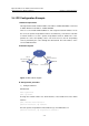
3.4 IPX Configuration Example
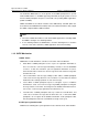
I. Network requirements
Through an IPX network, Switch A with a node address of 000f-e20f-0000 is connected
to Switch B with a node address of 000f-e20f-0001.
There is a server installed with NetWare 4.1 and assigned a network number of 2. On
the server, the packet encapsulation format is set to Ethernet_II. The client is a PC with
a network number of 3 and a packet encapsulation format of SNAP. The server
provides file service and printing service. The client accesses the file and printing
services provided by the server through the IPX network. The node address of the
server is 0000-0c91-f61f.
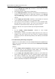
II. Network diagram
IPX
Vlan-int1
1000.000f-e20f-0000
Vlan-int2
2.000f-e20f-0000
Switch A
Server
Vl
3.000f-e2
Vlan-int1
1000.000f-e20f-0001
Switch B
Client
an-int2
0f-0001
Figure 3-1 IPX network diagram
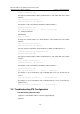
III. Configuration procedure
1) Configure Switch A.
# Enable IPX.
<H3C> system-view
[H3C] ipx enable
# Assign the network number 2 to VLAN interface 2 and enable IPX on the VLAN
interface.
[H3C] interface Vlan-interface 2
[H3C-Vlan-interface2] ipx network 2
# Set the packet encapsulation format to Ethernet_II on VLAN interface 2.
[H3C-Vlan-interface2] ipx encapsulation ethernet-2