
H3C S7500 Series Ethernet Switches Operation Manual


Operation Manual – Port Isolation
H3C S7500 Series Ethernet Switches Chapter 1
Port Isolation Configuration
1-2
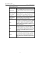
To do… Use the command… Remarks
Specify a description
string for the current
isolation group
description text
Optional
Add the specified port into
the isolation group
port interface-list
Optional
By default, an isolation
group contains no
Ethernet port.
Enter Ethernet port view
interface interface-type
interface-number
—
Add the current Ethernet
port to the specified
isolation group
port isolate group
group-id
Optional
By default, an isolation
group contains no
Ethernet port.
Note:
z An Ethernet port belongs to only one port isolation group. If you add an Ethernet port
to different isolation groups, the port belongs to only the latest isolation group to
which the port is added.
z Currently, cards of Type A (LS81FT48A, LS81FM24A, LS81FS24A, LS81GB8UA,
and LS81GT8UA) do not support the Port Isolation feature.
1.3 Displaying Port Isolation Configuration
To do… Use the command… Remarks
Display the configuration of
the created isolation group
display isolate port
[ group group-id ]
Available in any view.
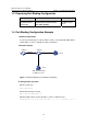
1.4 Port Isolation Configuration Example
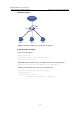
I. Network requirements
z PC 2, PC 3 and PC 4 connect to the switch ports Ethernet 2/0/2, Ethernet 2/0/3,
and Ethernet 2/0/4 respectively.
z It is desired that PC 2, PC 3 and PC 4 are isolated from each other so that they
cannot communicate with each other.