
H3C S7500 Series Ethernet Switches Operation Manual

Operation Manual – MSTP
H3C S7500 Series Ethernet Switches Chapter 1
MSTP Configuration
1-2
The switches in a network transfer BPDUs between each other to determine the
topology of the network. BPDUs carry enough information needed for switches to figure
out the spanning tree.
BPDUs used in STP fall into the following two categories:
z Configuration BPDUs: BPDUs of this type are used to maintain the spanning tree
topology.
z Topology change notification BPDU (TCN BPDU): BPDUs of this type are used to
notify the switches of network changes.
Similar to STP and RSTP, MSTP uses BPDUs to figure out spanning trees too. Besides,
the BPDUs of MSTP carry MSTP configuration information of the switches.
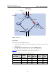
1.1.2 Basic MSTP Terminologies
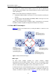
Figure 1-1 illustrates basic MSTP terms (assuming that MSTP is enabled on each
switch in this figure).
CST
BPDU
BPDU BPDU
A
D
CB
Region A0
VLAN 1 mapped to
VLAN 2 mapped to
Other VLANs mapp
Regi
VLAN
VLAN
Other
Region C0
VLAN 1 mapped to i
VLAN 2 mapped to i
Other VLANs mapped
Region D0
VLAN 1 mapped to instance 1,
B as regional root bridge
VLAN 2 mapped to instance 2,
C as regional root bridge
Other VLANs mapped to CIST
instance 1
instance 2
ed to CIST
on B0
1 mapped to instance 1
2 mapped to instance 2
VLANs mapped to CIST
nstance 1
nstance 2
to CIST
Figure 1-1 Basic MSTP terminologies
I. MST region
An MST region (multiple spanning tree region) comprises multiple
physically-interconnected MSTP-enabled switches and the corresponding network
segments connected to these switches. These switches have the same region name,
the same VLAN-to-MSTI mapping table and the same MSTP revision level.
A switched network can contain multiple MST regions. You can group multiple switches
into one MST region by using the corresponding MSTP configuration commands. For
example, all switches in region A0 shown in
Figure 1-1 have the same MST region