
H3C S7500 Series Ethernet Switches Operation Manual

Operation Manual – MSTP
H3C S7500 Series Ethernet Switches Chapter 1
MSTP Configuration
1-14
II. Configuration example
# Configure the current switch to operate in the STP-compatible mode.
<H3C> system-view
[H3C] stp mode stp
1.2.6 MST Region Maximum Hops Configuration
The maximum hop values configured on the region roots in an MST region limit the size
of the MST region.
A configuration BPDU contains a field that maintains the remaining hops of the
configuration BPDU. And a switch discards the configuration BPDUs whose remaining
hops are 0. After a configuration BPDU reaches a root bridge of an MSTI in an MST
region, the value of the remaining hops field in the configuration BPDU is decreased by
1 every time the configuration BPDU passes a switch. Such a mechanism disables the
switches beyond the maximum hops from participating in spanning tree generation,
and thus limits the size of an MST region.
With such a mechanism, the maximum hops configured on the switch operating as the
root bridge of the CIST or an MSTI in an MST region becomes the network diameter of
the spanning tree, which limits the size of the spanning tree in the current MST region.
The switches that are not root bridges in the MST region adopt the maximum hops
settings of their root bridges.
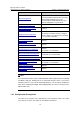
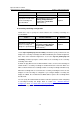
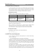
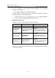
I. Configuration procedure
Follow these steps to configure the maximum hops for an MST region:
To do ...
Use the
command ...
Remarks
Enter system view
system-view
—
Configure the maximum
hops for the MST region
stp max-hops hops
Required
By default, the maximum hops
of an MST region are 20.
Note that only the maximum hops settings on the switches operating as region roots
can limit the size of the MST region.
II. Configuration example
# Configure the maximum hops of the MST region to be 30 (assuming that the current
switch operates as the region root).
<H3C> system-view
[H3C] stp max-hops 30