
H3C S7500 Series Ethernet Switches Operation Manual

Operation Manual – MSTP
H3C S7500 Series Ethernet Switches Chapter 1
MSTP Configuration
1-41
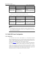
1.9 Displaying and Debugging MSTP
To do ... Use the command ...
Display spanning tree-related
information about the current switch
display stp [ instance instance-id ]
[ interface interface-list | slot slot-number ]
[ brief ]
Display the region configuration
information
display stp region-configuration
Clear MSTP-related statistics reset stp [ interface interface-list ]
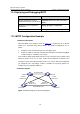
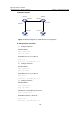
1.10 MSTP Configuration Example
I. Network requirements
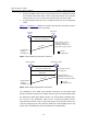
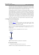
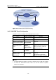
Implement MSTP in the network shown in Figure 1-7 to enable packets of different
VLANs to be forwarded along different MSTIs. The detailed configurations are as
follows:
z All switches in the network belong to the same MST region.
z Packets of VLAN 10, VLAN 30, VLAN 40, and VLAN 20 are forwarded along MSTI
1, MSTI 3, MSTI 4, and MSTI 0 respectively.
In this network, Switch A and Switch B operate on the convergence layer; Switch C and
Switch D operate on the access layer. VLAN 10 and VLAN 30 are limited in the
convergence layer and VLAN 40 is limited in the access layer. Switch A and Switch B
are configured as the root bridges of MSTI 1 and MSTI 3 respectively. Switch C is
configured as the root bridge of MSTI 4.
II. Network diagram
Switch A
Switch C
Permit:all VLAN
Permit:VLAN 20,40
Permit:
VLAN 10,20
Permit:
VLAN 10,20
Permit:
VLAN 20,30
Switch B
Switch D
Permit:
VLAN 20,30
Figure 1-7 Network diagram for implementing MSTP