
H3C S7500 Series Ethernet Switches Operation Manual

Operation Manual – Routing Protocol
H3C S7500 Series Ethernet Switches Chapter 2 Static Route Configuration
2-4
2.4 Static Route Configuration Example
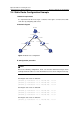
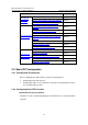
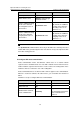
I. Network requirements
It is required that all the hosts/Layer 3 switches in the figure can interconnect with
each other by configuring static routes.
II. Network diagram
1.1.5.2/24
Switch BSwitch A
Switch C
Host C
Host A
Host B
1.1.5.1/24
1.1.1.1/24
1.1.1.2/24
1.1.2.2/24
1.1.2.1/24 1.1.3.2/24
1.1.3.1/24
1.1.4.1/24
1.1.4.2/24
Figure 2-1 Static route configuration
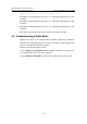
III. Configuration procedure
Note:
Before the following configuration, make sure that the Ethernet link layer works
normally and the IP addresses of the VLAN interfaces have been configured correctly.
# Configure static routes on Switch A.
[SwitchA] ip route-static 1.1.3.0 255.255.255.0 1.1.2.2
[SwitchA] ip route-static 1.1.4.0 255.255.255.0 1.1.2.2
[SwitchA] ip route-static 1.1.5.0 255.255.255.0 1.1.2.2
# Configure static routes on Switch B.
[SwitchB] ip route-static 1.1.2.0 255.255.255.0 1.1.3.1
[SwitchB] ip route-static 1.1.5.0 255.255.255.0 1.1.3.1
[SwitchB] ip route-static 1.1.1.0 255.255.255.0 1.1.3.1
# Configure static routes on Switch C.
[SwitchC] ip route-static 1.1.1.0 255.255.255.0 1.1.2.1