
H3C S7500 Series Ethernet Switches Operation Manual

Operation Manual – Routing Protocol
H3C S7500 Series Ethernet Switches Chapter 3 RIP Configuration
3-13
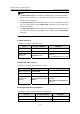
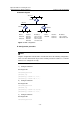
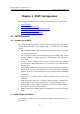
II. Network diagram
Switch A
Switch B
Switch C
Vlan-int 2
Ethernet
Vlan-int 4 Vlan-int 3
Vlan-int 1
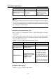
Device Interface IP address Device Interface IP address
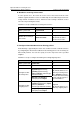
Switch A Vlan-int1 110.11.2.1/24 Switch B Vlan-int1 110.11.2.2/24
Vlan-int2 155.10.1.1/24 Vlan-int3 196.38.165.1/24
Switch C Vlan-int1 110.11.2.3/24
Vlan-int4 117.102.0.1/16
Figure 3-1 RIP configuration
III. Configuration procedure
Note:
Only the configuration related to RIP is listed below. Before the following configuration,
make sure the Ethernet link layer works normally and the IP addresses of VLAN
interfaces are configured correctly.
1) Configure Switch A
# Configure RIP.
<SwitchA>system-view
[SwitchA] rip
[SwitchA-rip] network 110.11.2.0
[SwitchA-rip] network 155.10.1.0
2) Configure Switch B
# Configure RIP.
<SwitchB>system-view
[SwitchB] rip
[SwitchB-rip] network 196.38.165.0
[SwitchB-rip] network 110.11.2.0
3) Configure Switch C
# Configure RIP.
<SwitchC>system-view