
H3C S7500 Series Ethernet Switches Operation Manual

Operation Manual – Routing Protocol
H3C S7500 Series Ethernet Switches Chapter 4 OSPF Configuration
4-28
4.9.2 Configuring OSPF Virtual Link
I. Network requirements
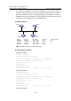
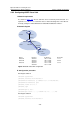
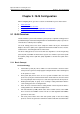
As shown in Figure 4-4, Area 2 and Area 0 are not directly interconnected. It is
required to use Area 1 as a transition area for interconnecting Area 2 and Area 0.
Correctly configure a virtual link between Switch B and Switch C in Area 1.
II. Network diagram
Area 0
Switch A
Switch C
Switch B
Vlan-int1
Area 1 Virtual link
Area 2
Vlan-int2
Vlan-int2
Vlan-int1
Vlan-int1
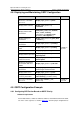
Device Interface IP interface Router ID
Switch A Vlan-int1 196.1.1.1/24 1.1.1.1
Switch B Vlan-int1 196.1.1.2/24 2.2.2.2
Vlan-int2 197.1.1.2/24
Switch C Vlan-int1 152.1.1.1/24 3.3.3.3
Vlan-int2 197.1.1.1/24
Figure 4-4 OSPF virtual link configuration
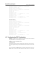
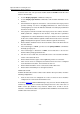
III. Configuration procedure
# Configure Switch A.
<SwitchA> system-view
[SwitchA] interface Vlan-interface 1
[SwitchA-Vlan-interface1] ip address 196.1.1.1 255.255.255.0
[SwitchA-Vlan-interface1] quit
[SwitchA] router id 1.1.1.1
[SwitchA] ospf
[SwitchA-ospf-1] area 0
[SwitchA-ospf-1-area-0.0.0.0] network 196.1.1.0 0.0.0.255
# Configure Switch B.
<SwitchB> system-view
[SwitchB] interface vlan-interface 1