
H3C S7500 Series Ethernet Switches Operation Manual

Operation Manual – Routing Protocol
H3C S7500 Series Ethernet Switches Chapter 5 IS-IS Configuration
5-24
5.5 Integrated IS-IS Configuration Example
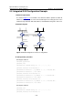
I. Network requirements
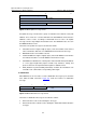
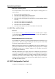
As shown in Figure 5-4, four S7500 series Ethernet switches (Switch A, Switch B,
Switch C, and Switch D) are interconnected through IS-IS routing protocol. In the
network design, Switch A, Switch B, Switch C, and Switch D belong to the same area.
II. Network diagram
Switch A
Switch D
Switch B
Switch C
Vlan-int102
100.20.0.1/24
Vlan-int101
200.10.0.1/24
Vlan-int102
100.20.0.2/24
Vlan-int101
100.0.0.1/24
Vlan-int102
200.0.0.1/24
Vlan-int100
1 00.10.0 .1/24
Vlan-int100
100.10.0.2/24
Vlan-int101
200.10.0.2/24
Vlan-int100
200.20.0.1/24
Vlan-int100
100.30.0.1/24
Figure 5-4 Network diagram for IS-IS basic configuration
III. Configuration procedure
# Configure Switch A.
<SwitchA> system-view
[SwitchA] isis
[SwitchA-isis] network-entity 86.0001.0000.0000.0005.00
[SwitchA] interface vlan-interface 100
[SwitchA-Vlan-interface100] ip address 100.10.0.1 255.255.255.0
[SwitchA-Vlan-interface100] isis enable
[SwitchA] interface vlan-interface 101
[SwitchA-Vlan-interface101] ip address 100.0.0.1 255.255.255.0
[SwitchA-Vlan-interface101] isis enable
[SwitchA] interface vlan-interface 102
[SwitchA-Vlan-interface102] ip address 100.20.0.1 255.255.255.0
[SwitchA-Vlan-interface102] isis enable
# Configure Switch B.
[SwitchB] isis
[SwitchB-isis] network-entity 86.0001.0000.0000.0006.00
[SwitchB] interface vlan-interface 101