
H3C S7500 Series Ethernet Switches Operation Manual


Operation Manual – Routing Protocol
H3C S7500 Series Ethernet Switches Chapter 6 BGP Configuration
6-27
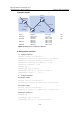
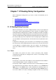
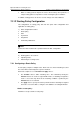
II. Network diagram
Switch A
AS 100
VLAN -int4
Switch C
Switch B
Switch D
AS 200
Router
Reflector
VLAN -int3
VLAN-int2
VLAN-int100
Device Interface IP interface AS
Switch A Vlan-int 100 1.1.1.1/8
Vlan-int 2 192.1.1.1/24
100
Switch B Vlan-int 2 192.1.1.2/24
Vlan-int 3 193.1.1.2/24
Switch C Vlan-int 3 193.1.1.1/24
Vlan-int 4 194.1.1.1/24
Switch D Vlan-int 4 194.1.1.2/24
200
Figure 6-6 Diagram for configuring a BGP RR
III. Configuration procedure
1) Configure Switch A.
[SwitchA] interface vlan-interface 2
[SwitchA-Vlan-interface2] ip address 192.1.1.1 255.255.255.0
[SwitchA-Vlan-interface2] interface Vlan-interface 100
[SwitchA-Vlan-interface100] ip address 1.1.1.1 255.0.0.0
[SwitchA-Vlan-interface100] quit
[SwitchA] bgp 100
[SwitchA-bgp] group ex external
[SwitchA-bgp] peer 192.1.1.2 group ex as-number 200
[SwitchA-bgp] network 1.0.0.0 255.0.0.0
2) Configure Switch B.
# Configure VLAN 2.
[SwitchB] interface Vlan-interface 2
[SwitchB-Vlan-interface2] ip address 192.1.1.2 255.255.255.0
# Configure VLAN 3.
[SwitchB] interface Vlan-interface 3
[SwitchB-Vlan-interface3] ip address 193.1.1.2 255.255.255.0
# Configure a BGP peer.
[SwitchB] bgp 200
[SwitchB-bgp] group ex external
[SwitchB-bgp] peer 192.1.1.1 group ex as-number 100