
H3C S7500 Series Ethernet Switches Operation Manual

Operation Manual – Routing Protocol
H3C S7500 Series Ethernet Switches Chapter 7 IP Routing Policy Configuration
7-10
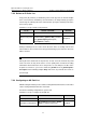
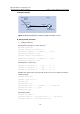
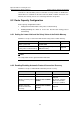
II. Network diagram
Area 0
Vlan-Int 200
Router ID:1.1.1.1
Switch A
Switch B
Router ID:
2.2.2.2
12.0.0.1/8
Static 20.0.0.0/8
30.0.0.0 /8
40.0.0.0 /8
10.0.0.1/8
10.0.0 .2/8
Vlan-Int 100
Figure 7-1 Networking diagram for filtering routing information received
III. Configuration procedure
1) Configure Switch A:
# Configure the IP addresses of the interfaces.
<SwitchA> system-view
[SwitchA] interface vlan-interface 100
[SwitchA-Vlan-interface100] ip address 10.0.0.1 255.0.0.0
[SwitchA-Vlan-interface100] quit
[SwitchA] interface vlan-interface 200
[SwitchA-Vlan-interface200] ip address 12.0.0.1 255.0.0.0
[SwitchA-Vlan-interface200] quit
# Configure three static routes.
[SwitchA] ip route-static 20.0.0.1 255.0.0.0 12.0.0.2
[SwitchA] ip route-static 30.0.0.1 255.0.0.0 12.0.0.2
[SwitchA] ip route-static 40.0.0.1 255.0.0.0 12.0.0.2
# Enable the OSPF protocol and specify the ID of the area to which the interface
10.0.0.1 belongs.
<SwitchA> system-view
[SwitchA] router id 1.1.1.1
[SwitchA] ospf
[SwitchA-ospf-1] area 0
[SwitchA-ospf-1-area-0.0.0.0] network 10.0.0.0 0.255.255.255
[SwitchA-ospf-1-area-0.0.0.0] quit
[SwitchA-ospf-1]quit
# Configure an ACL.
[SwitchA] acl number 2000
[SwitchA-acl-basic-2000] rule deny source 30.0.0.0 0.255.255.255
[SwitchA-acl-basic-2000] rule permit source any