
H3C S7500 Series Ethernet Switches Operation Manual


Operation Manual – Multicast
H3C S7500 Series Ethernet Switches Chapter 1
Multicast Overview
1-8
Note:
Like having reserved the private network segment 10.0.0.0/8 for unicast, IANA has also
reserved the network segments ranging from 239.0.0.0 to 239.255.255.255 for
multicast. These are administratively scoped addresses. With the administratively
scoped addresses, you can define the range of multicast domains flexibly to isolate IP
addresses between different multicast domains, so that the same multicast address
can be used in different multicast domains without causing collisions.
II. Ethernet multicast MAC address
When a unicast IP packet is transmitted in an Ethernet network, the destination MAC
address is the MAC address of the receiver. When a multicast packet is transmitted in
an Ethernet network, a multicast MAC address is used as the destination address
because the destination is a group with an uncertain number of members.
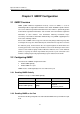
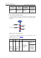
As stipulated by IANA, the high-order 24 bits of a multicast MAC address are 0x01005e,
while the low-order 23 bits of a MAC address are the low-order 23 bits of the multicast
IP address.
Figure 1-4 describes the mapping relationship:
XXXX X
XXXX XXXX XXXX XXXX1110 XXXX
0XXX XXXX XXXX XXX
XXXX XXXX
X XXXX XXXX0000 0001 0000 0000 0101 1110
32-bit IP address
48-bit MAC address
5 bits lost
25-bit MAC address prefix
……
23 bits
mapped
Figure 1-4 Mapping relationship between multicast IP address and multicast MAC
address
The high-order four bits of the IP multicast address are 1110, representing the multicast
ID. Only 23 bits of the low-order 28 bits are mapped to a MAC address Thus five bits of
the multicast IP address are lost. As a result, 32 IP multicast addresses are mapped to
the same MAC address.
1.2.2 IP Multicast Protocols
IP multicast protocols include multicast group management protocols and multicast
routing protocols.
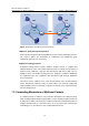
Figure 1-5 describes the positions of multicast-relevant protocols in
the network.