
H3C S7500 Series Ethernet Switches Operation Manual

Operation Manual – Multicast
H3C S7500 Series Ethernet Switches Chapter 3
IGMP Snooping Configuration
3-14
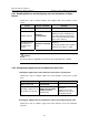
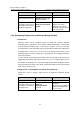
Device
Device
Device ID
type
Port
connected to
Description
the port
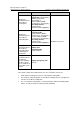
Switch D
Layer 2
switch
The port
connecting to
the upper-layer
switch is
configured as a
trunk port.
—
Switch C is
connected to users
belonging to VLAN 5
through VLAN 7
where the IGMP
snooping feature is
enabled.
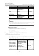
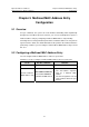
Configure VLAN 1024 as a multicast VLAN and configure VLAN 2 through VLAN 7 as
multicast sub-VLANs.
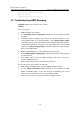
II. Network diagram
RouterA
SwitchB
SwitchC SwitchD
GE2/0/1
VLAN 1024
GE0/0/0
GE2/0/2
VLAN 2-VLAN 4
GE
VL
2/0/3
AN 5-VLAN 7
HostC
(VLAN4)
HostB
(VLAN 3 )
HostA
(VLAN2)
HostF
(VLAN7)
HostE
(VLAN6)
HostD
(VLAN 5 )
n
Figure 3-4 Network diagram for multicast VLAN configuratio
III. Configuration procedure
# Configure Router A.
<Router-A> system-view
[Router-A] multicast routing-enable
[Router-A] interface GigabitEthernet0/0/0
[Router-A-GigabitEthernet0/0/0] pim sm
[Router-A-GigabitEthernet0/0/0] igmp enable
[Router-A-GigabitEthernet0/0/0] quit
[Router-A]
# Configure Switch B.
<H3C> system-view
[H3C] igmp-snooping enable
[H3C] vlan 1024
[H3C-vlan1024]igmp-snooping enable