
H3C S7500 Series Ethernet Switches Operation Manual


Operation Manual – Multicast
H3C S7500 Series Ethernet Switches Chapter 6
IGMP Configuration
6-5
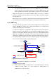
z On VLAN interface 2, configure VLAN interface 1 as the outbound IGMP Proxy
interface to external networks. You must enable the IGMP protocol on the interface
first, and then configure the igmp proxy command.
Configure Switch A as follows:
z Enable multicast routing and configure the IGMP protocol on VLAN interface 1.
z Configure the pim neighbor-policy command to filter PIM neighbors in the
network segment 33.33.33.0/24. That is, Switch A does not consider Switch B as
its PIM neighbor.
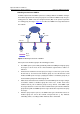
In this case, when VLAN interface 2 of Switch B of the leaf network receives an IGMP
join or IGMP leave message sent by the host, it will change the source address of the
IGMP message into the address of VLAN interface 1 (33.33.33.2) and send the
information to VLAN interface 1 of Switch A. For Switch A, this works as if there is a
host directly connected to VLAN interface 1.
Similarly, when Switch B receives an IGMP general group or group-specific query
message from the Layer 3 Switch A, it will also change the source address of the query
message into the IP address of VLAN interface 2 (22.22.22.1) and send the message
from VLAN interface 2.
In
Figure 6-2, VLAN interface 2 of Switch B is called the client interface and VLAN
interface 1 of Switch B is called the proxy interface.
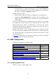
6.2 IGMP Configuration
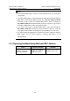
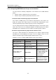
Complete the following tasks to configure IGMP:
Task Remarks
Configuring IGMP Version Optional
Configuring IGMP Query Messages Optional
Configuring IGMP Multicast Groups on the Interface Optional
Configuring Router Ports to Join the Specified Multicast Group Optional
Configuring IGMP Proxy Optional
Configuring Suppression on IGMP Report Messages Optional
Removing the Joined IGMP Groups from the Interface Optional
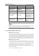
6.2.1 Configuring IGMP Version
Follow these steps to configure IGMP version: