
H3C S7500 Series Ethernet Switches Operation Manual

Operation Manual – Multicast
H3C S7500 Series Ethernet Switches Chapter 7
PIM Configuration
7-19
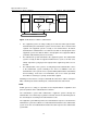
[H3C-Vlan-interface10] quit
[H3C] interface Vlan-interface 11
[H3C-Vlan-interface11] ip address 2.2.2.2 255.255.0.0
[H3C-Vlan-interface11] pim dm
[H3C-Vlan-interface11] quit
[H3C] interface Vlan-interface 12
[H3C-Vlan-interface12] ip address 3.3.3.3 255.255.0.0
[H3C-Vlan-interface12] pim dm
7.6.2 PIM-SM Configuration Example
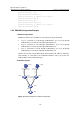
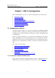
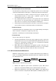
I. Network requirements
All Ethernet switches are reachable for each other in the practical network.
z LS_A is connected to LS_B through VLAN-interface 10, to Host A through
VLAN-interface 11 and to LS_C through VLAN-interface 12.
z LS_B is connected to LS_A through VLAN-interface 10, to LS_C through
VLAN-interface 11 and to LS_D through VLAN-interface 12.
z LS_C is connected to Host B through VLAN-interface 10, to LS_B through
VLAN-interface 11 and to LS_A through VLAN-interface 12.
Host A is the receiver of the multicast group whose multicast IP address is 225.0.0.1.
Host B begins to send data to the destination 225.0.0.1 and LS_A receives the
multicast data from Host B through LS_B.
II. Network diagram
LS_D
LS_B
LS_C
N
1
1
A
N
1
1
2
VLAN10
HostB
LS_A
VLAN 12
V
L
A
N
1
0
V
L
A
V
L
V
L
A
N
1
0
VLAN 1
VLAN 12
VLAN11
HostA
Figure 7-8 Network diagram for PIM-SM configuration