
H3C S7500 Series Ethernet Switches Operation Manual

Operation Manual – VRRP-HA
H3C S7500 Series Ethernet Switches Chapter 1
VRRP Configuration
1-1
Chapter 1 VRRP Configuration
When configuring VRRP, go to these sections for information you are interested in:
z VRRP Overview
z VRRP Configuration
z Displaying and Maintaining VRRP
z VRRP Configuration Examples
z Troubleshooting VRRP
1.1 VRRP Overview
Virtual Router Redundancy Protocol (VRRP) is a fault-tolerant protocol.
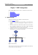
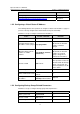
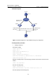
As shown in Figure 1-1, in general,
z A default route (for example, the next hop address of the default route is
10.100.10.1, as shown in the following figure) is configured for every host on a
network.
z The packets destined for the external network segments and sourced from these
hosts go through the default routes to the Layer 3 Switch, implementing
communication between these hosts and the external network.
z If Switch fails, all the hosts on this segment taking Switch as the next-hop through
the default routes are cut off from the external network.
Host 1
Ethernet
Switch
Network
Host 2
10.100.10.7 10.100.10.8
10.100.10.1
Host 3
10.100.10.9
g
Figure 1-1 LAN networkin
VRRP, designed for LANs with multicast and broadcast capabilities (such as Ethernet),
settles the problem caused by switch failures.