
H3C S7500 Series Ethernet Switches Operation Manual

Operation Manual – VRRP-HA
H3C S7500 Series Ethernet Switches Chapter 1
VRRP Configuration
1-9
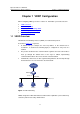
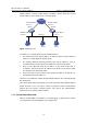
1.4 VRRP Configuration Examples
1.4.1 Single-VRRP Backup Group Configuration
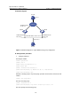
I. Network requirements
Host A uses the VRRP virtual router comprising switch A and switch B as its default
gateway to visit host B on the Internet.
The information about the VRRP backup group is as follows:
z VRRP backup group ID: 1
z Virtual router IP address: 202.38.160.111
z Master switch: Switch A
z Backup switch: Switch B
z Preemptive mode: enabled
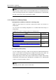
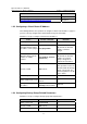
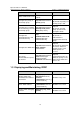
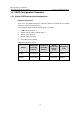
Table 1-1 Network description
Switch
Ethernet port
connecting
to Host A
IP address of
the VLAN
interface
Switch
priority in the
backup
group
Preemptive
mode
LSW-A Ethernet 2/0/6
202.38.160.1/
24
110 Enabled
LSW-B Ethernet 2/0/5
202.38.160.2/
24
100 (default) Enabled