
H3C S7500 Series Ethernet Switches Operation Manual

Operation Manual – VRRP-HA
H3C S7500 Series Ethernet Switches Chapter 1
VRRP Configuration
1-12
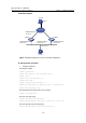
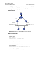
II. Network diagram
LSW A
Host A
Internet
Host B
VLAN-Interface3:
10.100.10.2
Virtual IP address
202.38.160.111
VLAN-Interface2:
202.38.160.1
202.38.160.3
10.2.3.1
LSW B
VLAN-Interface2:
202.38.160.2
n
Figure 1-4 Network diagram for interface tracking configuratio
III. Configuration procedure
z Configure Switch A.
# Configure VLAN 2.
<LSW-A> system-view
System View: return to User View with Ctrl+Z.
[LSW-A] vlan 2
[LSW-A-vlan2] port Ethernet 2/0/6
[LSW-A-vlan2] quit
[LSW-A] interface Vlan-interface 2
[LSW-A-Vlan-interface2] ip address 202.38.160.1 255.255.255.0
[LSW-A-Vlan-interface2] quit
# Configure that the virtual router can be pinged.
[LSW-A] vrrp ping-enable
# Create a backup group.
[LSW-A] interface Vlan-interface 2
[LSW-A-Vlan-interface2] vrrp vrid 1 virtual-ip 202.38.160.111
# Set the priority for the backup group.
[LSW-A-Vlan-interface2] vrrp vrid 1 priority 110