
H3C S7500 Series Ethernet Switches Operation Manual

Operation Manual – DHCP
H3C S7500 Series Ethernet Switches Chapter 3
DHCP Relay Agent Configuration
3-9
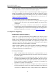
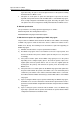
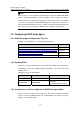
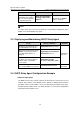
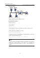
II. Network diagram
Switch B
DHCP server
Vlan-int1
38.1.2/24
Switch A
DHCP relay agent
DHCP client DHCP client
DHCP clientDHCP client
Vlan-int1
202.38.1.1/24
Vlan-int2
10.110.1.1/24
202.
Switch B
DHCP server
Vlan-int1
38.1.2/24
Switch A
DHCP relay agent
DHCP client DHCP client
DHCP clientDHCP client
Vlan-int1
202.38.1.1/24
Vlan-int2
10.110.1.1/24
202.
Switch B
DHCP server
Vlan-int1
38.1.2/24
Switch A
DHCP relay agent
DHCP client DHCP client
DHCP clientDHCP client
Vlan-int1
202.38.1.1/24
Vlan-int2
10.110.1.1/24
202.
Figure 3-2 Network diagram for DHCP relay agent
III. Configuration procedure
# Enter system view.
<H3C> system-view
# Enable DHCP.
[H3C] dhcp enable
# Create DHCP server group 1 and configure an IP address of 202.38.1.2 for it.
[H3C] dhcp-server 1 ip 202.38.1.2
# Map VLAN-interface 2 to DHCP server group 1.
[H3C] interface Vlan-interface 2
[H3C-Vlan-interface2] dhcp-server 1
# Configure an IP address for VLAN-interface 2, so that this interface is on the same
network segment with the DHCP clients.
[H3C-Vlan-interface2] ip address 10.110.1.1 255.255.0.0
Note:
You need to perform corresponding configurations on the DHCP server to enable the
DHCP clients to obtain IP addresses from the DHCP server. The DHCP server
configurations vary with different DHCP server devices, so the configurations are
omitted.