
H3C S7500 Series Ethernet Switches Operation Manual

Operation Manual – QoS
H3C S7500 Series Ethernet Switches Chapter 1
QoS Configuration
1-4
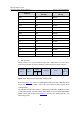
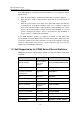
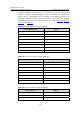
DSCP precedence DSCP precedence
Keyword
(decimal) (binary)
af23 22 010110
af31 26 011010
af32 28 011100
af33 30 011110
af41 34 100010
af42 36 100100
af43 38 100110
cs1 8 001000
cs2 16 010000
cs3 24 011000
cs4 32 100000
cs5 40 101000
cs6 48 110000
cs7 56 111000
default (be) 0 000000
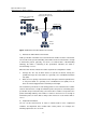
2) 802.1p priority
802.1p priority lies in a layer 2 frame headers and is applicable to occasions where
layer 3 packet headers do not need analysis but QoS must be assured at layer 2.
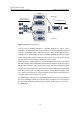
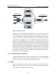
Length/Type Data
6 bytes 6 bytes 4 bytes 2 bytes
46~1500 bytes 4 bytes
TPID TCI
Source
Address
Destination
Address
802.1Q
header
FCS
(CRC
-32)
r
Figure 1-2 An Ethernet frame with a 802.1Q tag heade
As shown in
Figure 1-2, each host supporting 802.1Q protocol adds a 4-bit 802.1Q tag
header after the source address field of the former Ethernet frame header when
sending packets.
The 4-bit 802.1Q tag header contains a 2-bit tag protocol identifier (TPID) whose value
is 8100 and a 2-bit tag control information (TCI). TPID is a new class defined by IEEE to
identify a frame with an 802.1Q tag.
Figure 1-3 describes the detailed contents of an
802.1Q tag header.