
H3C S7500 Series Ethernet Switches Operation Manual

Operation Manual – Mirroring
H3C S7500 Series Ethernet Switches Chapter 1
Mirroring Configuration
1-3
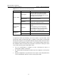
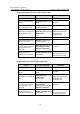
Table 1-1 Ports involved in the mirroring operation
Switch Ports involved Function
Source port
Port to be mirrored; copies user data
packets to the specified reflector port
through local port mirroring. There can be
more than one source port.
Reflector port
Receives user data packets that are
mirrored on a local port.
Source switch
Trunk port
Sends mirrored packets to the intermediate
switch or the destination switch.
Intermediate
switch
Trunk port
Sends mirrored packets to the destination
switch.
Two Trunk ports are necessary for the
intermediate switch to be connected to
devices that are connected to the source
switch and the destination switch.
Trunk port
Receives remote mirrored packets.
Destination
switch
Destination port
Monitors remote mirrored packets
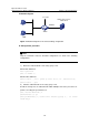
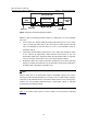
To implement remote port mirroring, you need to define a special VLAN, called
remote-probe VLAN, on all the three types of switches. In this VLAN, no normal data
but only mirrored packets are transmitted. All mirrored packets will be transferred to the
specified port of the destination switch from the source switch through this VLAN. Thus,
the destination switch can monitor the port packets sent from the remote ports of the
source switch. Remote-probe VLAN requires that:
z You are recommended to configure all ports connecting the devices in
remote-probe VLAN as Trunk ports.
z The default VLAN and management VLAN cannot be configured as remote-probe
VLAN.
z Required configurations are performed to ensure Layer 2 connectivity between the
source and destination switches over the remote-probe VLAN.