
H3C S7500 Series Ethernet Switches Operation Manual

Operation Manual – Mirroring
H3C S7500 Series Ethernet Switches Chapter 1
Mirroring Configuration
1-7
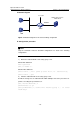
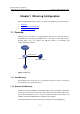
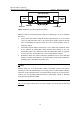
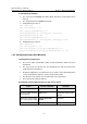
IV. Configuration Example
z The source port is GigabitEthernet 2/0/1. Mirror all packets received and sent via
this port.
z The destination port is GigabitEthernet 2/0/4.
1) Configuration procedure 1:
<H3C> system-view
[H3C] mirroring-group 1 local
[H3C] interface GigabitEthernet 2/0/4
[H3C-GigabitEthernet2/0/4] mirroring-group 1 monitor-port
[H3C-GigabitEthernet2/0/4] quit
[H3C] interface GigabitEthernet 2/0/1
[H3C-GigabitEthernet2/0/1] mirroring-group 1 mirroring-port both
2) Configuration procedure 2:
<H3C> system-view
[H3C] mirroring-group 1 local
[H3C] mirroring-group 1 monitor-port GigabitEthernet 2/0/4
[H3C] mirroring-group 1 mirroring-port GigabitEthernet 2/0/1 both
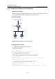
1.3.2 Configuring Remote Port Mirroring
I. Configuration prerequisites
z The source switch, intermediate switch, and the destination switch have been
determined.
z The source port, the reflector port, the destination port, and the remote-probe
VLAN have been determined.
z Required configurations are performed to ensure Layer 2 connectivity between the
source and destination switches over the remote-probe VLAN.
z The direction of the packets to be monitored has been determined.
z The remote-probe VLAN is enabled.
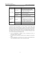
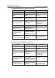
II. Configuring remote port mirroring on the source switch
To do… Use the command… Remarks
Enter system view
system-view
—
Create a VLAN and enter
its VLAN view
vlan vlan-id
vlan-id is the ID of the
destination remote-probe
VLAN.
Define the current VLAN
as a remote-probe VLAN
remote-probe vlan
enable
Required
Exit current view
quit
—