
H3C S7500 Series Ethernet Switches Operation Manual

Operation Manual – Mirroring
H3C S7500 Series Ethernet Switches Chapter 1
Mirroring Configuration
1-12
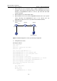
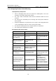
z Define Switch A as the destination switch; configure GigabitEthernet 2/0/2, the
port that is connected to the data detect device, as the destination port for remote
mirroring. Set GigabitEthernet 2/0/2 to an Access port, with STP and LACP
functions disabled.
z Define Switch B as the intermediate switch.
z Define Switch C as the source switch, GigabitEthernet 2/0/2 as the source port for
remote mirroring, and GigabitEthernet 2/0/3 as the reflector port. Set
GigabitEthernet 2/0/3 to an Access port, with STP and LACP disabled.
2) Network diagram
Switch C
GE2/0/ 1
PC1
Switch B
GE 2/ 0/ 2 GE2 /0/ 1
GE
GE2/0/2
Switch A
2/0/1
GE2/0/2
Data detect device
n
Figure 1-3 Network diagram for remote port mirroring configuratio
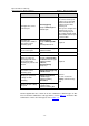
3) Configuration procedure
# Configure Switch C.
<H3C> system-view
[H3C] vlan 10
[H3C-vlan10] remote-probe vlan enable
[H3C-vlan10] quit
[H3C] interface GigabitEthernet 2/0/1
[H3C-GigabitEthernet2/0/1] port link-type trunk
[H3C-GigabitEthernet2/0/1] port trunk permit vlan 10
[H3C-GigabitEthernet2/0/1] quit
[H3C] mirroring-group 1 remote-source
[H3C] mirroring-group 1 mirroring-port GigabitEthernet 2/0/2 inbound
[H3C] mirroring-group 1 reflector-port GigabitEthernet 2/0/3
[H3C] mirroring-group 1 remote-probe vlan 10
[H3C] display mirroring-group remote-source
mirroring-group 1:
type: remote-source
status: active
mirroring port:
GigabitEthernet2/0/2 inbound