
H3C S7500 Series Ethernet Switches Operation Manual

Operation Manual – UDP-Helper
H3C S7500 Series Ethernet Switches Chapter 1
UDP-Helper Configuration
1-4
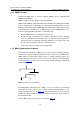
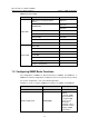
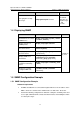
1.4.2 Network diagram
IP network
Vlan-int1
10.110.1.1/16
Switch
(UDP HELPER)
Vlan-int1
202.38.1.2/24
Switch
Server
Figure 1-1 Network diagram for UDP-Helper configuration
1.4.3 Configuration procedure
Note:
This example assumes that the route between the switch and the network segment
202.38.1.0/24 is reachable.
# Enable UDP-Helper.
<H3C> system-view
[H3C] udp-helper enable
# Configure port 55 as a UDP-Helper destination port.
[H3C] udp-helper port 55
# Configure the server with the IP address of 202.38.1.2 as a destination server for the
UDP broadcast packets.
[H3C] interface Vlan-interface 1
[H3C-Vlan-interface1] ip address 10.110.1.1 16
[H3C-Vlan-interface1] udp-helper server 202.38.1.2