
H3C S7500 Series Ethernet Switches Operation Manual


Operation Manual – NTP
H3C S7500 Series Ethernet Switches Chapter 1
NTP Configuration
1-3
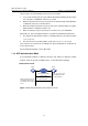
The procedures of synchronizing system clocks are as follows:
z LS_A sends an NTP packet to LS_B, with the timestamp identifying the time when
it is sent (that is, 10:00:00am, noted as T
1
) carried.
z When the packet arrives at LS_B, LS_B inserts its own timestamp, which identifies
11:00:01am (noted as T
2
) into the packet.
z Before this NTP packet leaves LS_B, LS_B inserts its own timestamp once again,
which identifies 11:00:02am (noted as T
3
).
z When receiving the response packet, the local time of LS_A is 10:00:03am.
At this time, LS_A has enough information to calculate the following two parameters:
z The delay for an NTP packet to make a round trip between LS_A and LS_B: delay
= (T
4
-T
1
)-(T
3
-T
2
).
z The time offset of LS_A with regard to LS_B: offset = ((T
2
-T
1
) + (T
3
-T
4
))/2.
LS_A can then set its own clock according to the above information to synchronize its
clock to that of LS_B.
For the detailed information, refer to RFC1305.
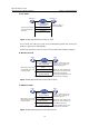
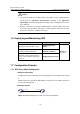
1.1.3 NTP Implementation Mode
To accommodate networks of different structures and switches in different network
positions, NTP can operate in multiple modes, as described in the following.
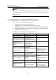
I. Client/Server mode
Server
Clock synchronization
request packet
Response packet
Network
Client
Wor
auto
a re
Filters and selects a clocks
and synchronize the local
clock to that of the preferred
server
ks in server mode
matically and send
sponse packet
e
Figure 1-2 NTP implementation mode: client/Sever mod