
H3C S7500 Series Ethernet Switches Operation Manual

Operation Manual – NTP
H3C S7500 Series Ethernet Switches Chapter 1
NTP Configuration
1-12
Caution:
z The source IP address in an NTP packet is the address of the sending interface
specified by the ntp-service unicast-server command or the ntp-service
unicast-peer command if you provide the address of the sending interface in these
two commands.
z Dynamic connections can only be established when a switch operates in passive
peer mode, NTP broadcast client mode, or NTP multicast client mode. In other
modes, the connections established are static.
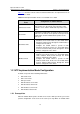
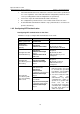
1.6 Displaying and Maintaining NTP
To do... Use the command... Remarks
Display the status of NTP service
display ntp-service
status
Display the information about the
sessions maintained by NTP
display ntp-service
sessions [ verbose ]
Display the brief information about the
NTP time servers of the reference
clock sources that the local device
traces to
display ntp-service trace
Available in
any view
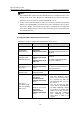
1.7 Configuration Example
1.7.1 NTP Server Mode Configuration
I. Network requirements
Configure the local clock of S7500-1 to be the NTP master clock, with the stratum being
2.
S7500-2 operates in client mode, with S7500-1 as the time server. S7500-1 operates in
server mode automatically.
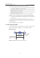
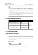
II. Network diagram
1.0.1.11/24
S7500-1
1.0.1.12/24
S7500-2
Figure 1-6 Network diagram for the NTP server mode configuration