
H3C S7500 Series Ethernet Switches Operation Manual


Operation Manual – System Maintenance and Debugging
H3C S7500 Series Ethernet Switches Chapter 4
Device Management
4-8
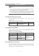
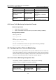
To do… Use the command… Remarks
Enter system view
system-view
—
Enter Ethernet interface
view
interface interface-type
interface-number
—
Enable Layer 3
connectivity detection
function
uplink monitor ip
ip-address
Required
Display information about
Layer 3 connectivity
between the local device
and the remote device
display uplink monitor
Optional
You can execute the
display command in any
view.
4.4.3 Layer 3 Connectivity Detection Configuration Example
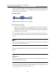
I. Network requirements
z The physical link between the local peer and the remote peer is correct. The local
peer port that is used to connect is Ethernet 4/0/1.
z The IP address of the Lay 3 interface of the remote peer is 1.1.1.1.
II. Configuration procedure
# Enter system view.
<H3C> system-view
[H3C]
# Enter Ethernet interface view.
[H3C] interface Ethernet 4/0/1
# Enable Layer 3 connectivity detection on Ethernet 4/0/1 interface and specify the IP
address of the device (1.1.1.1) to be detected.
[H3C-Ethernet4/0/1] uplink monitor ip 1.1.1.1
4.5 Configuring Queue Traffic Monitoring
Upon enabling queue traffic monitoring on a switch, the switch monitors the queue
traffic and relieves blocks in the output queue of its interfaces.
The criterion used to distinguish a block is that the queue is full, and the traffic of the
corresponding interface is less than the specified threshold.
4.5.1 Queue Traffic Monitoring Configuration Task
The following describes configuration tasks of queue traffic monitoring.
Follow these steps to configure queue traffic monitoring: