
H3C S7500 Series Ethernet Switches Operation Manual


Operation Manual – NAT, Netstream, Policy Routing
H3C S7500 Series Ethernet Switches Chapter 3
Policy Routing Configuration
3-3
3.4 Policy Routing Configuration Example
3.4.1 Configuration Example
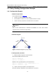
I. Network requirements
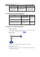
In the network shown in Figure 3-1:
z An LPU is installed in slot 5 of the switch.
z The IP address of Host 1 is 1.0.0.1, and that of Host 2 is 2.0.0.1.
z Set the next hops of packets sourced from Host 1 to 2.0.0.1.
Caution:
Make sure the VLAN interfaces of GE2/0/1 and GE2/0/2 are on the same network
segments of Host 1 and Host 2 respectively.
II. Network diagram
Host 2
1.0.0.1/8
GE2/
Host 1
GE2/0/1
VLAN 2
0/3
GE2/0/2
2.0.0.1/8
VLAN 3
g
Figure 3-1 Network diagram for policy routin
III. Configuration procedure
1) Define an ACL for packets source from PC1.
# Create ACL 2000 and enter its view.
<H3C S7500>system-view
[H3C S7500] acl number 2000
# Define a rule to permit packets sourced from Host 1.
[H3C S7500-acl-basic-2000] rule 0 permit source 1.0.0.1 0
[H3C S7500-acl-basic-2000] quit
2) Set the next hop for packets sourced from Host 1.
# Set the next hop of all packets sourced from Host 1 to 2.0.0.1.