DHCP Configuration Examples H3C S7500 Series Ethernet Switches Release 3135 Table of Contents Table of Contents Chapter 1 DHCP Functions Overview ......................................................................................... 1-1 1.1 Supported DHCP Functions .............................................................................................. 1-1 1.2 Configuration Guide........................................................................................................... 1-2 1.2.
DHCP Configuration Examples H3C S7500 Series Ethernet Switches Release 3135 Abstract DHCP Configuration Examples Keywords: DHCP, Option 82 Abstract: This document describes DHCP configuration and application on Ethernet switches in specific networking environments. Based on the different roles played by the devices in the network, the functions and applications of DHCP server, DHCP relay agent, DHCP snooping, and DHCP Option 82 are covered. Acronym: DHCP (Dynamic Host Configuration Protocol).
DHCP Configuration Examples H3C S7500 Series Ethernet Switches Release 3135 Chapter 1 DHCP Functions Overview Chapter 1 DHCP Functions Overview Note: The configuration procedures and commands described in this manual are tested on H3C S7500 series switches running Release 3135. If you encounter any configuration failure on a device running a different release, refer to the corresponding configuration and command manuals. 1.
DHCP Configuration Examples H3C S7500 Series Ethernet Switches Release 3135 Chapter 1 DHCP Functions Overview 1.2 Configuration Guide 1.2.1 Configuring the DHCP Server The DHCP server can be configured to assign IP addresses from a global or interface address pool. These two configuration methods are applicable to the following environments: If the DHCP server and DHCP clients are on the same network segment, both z methods can be applied.
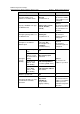
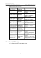
DHCP Configuration Examples H3C S7500 Series Ethernet Switches Release 3135 Chapter 1 DHCP Functions Overview Operation Command Description Required Configure WINS server addresses for DHCP clients nbns-list ip-address&<1-8> Specify a NetBIOS node type for DHCP clients netbios-type { b-node | h-node | m-node | p-node } By default, no WINS server addresses are configured. Optional By default, the DHCP clients are h-nodes if the command is not specified.
DHCP Configuration Examples H3C S7500 Series Ethernet Switches Release 3135 Chapter 1 DHCP Functions Overview Operation Command interface interface-type interface-number On the current interface Configure the global address pool mode Description dhcp select global Optional quit By default, an interface operates in the global address pool mode.
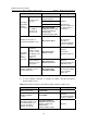
DHCP Configuration Examples H3C S7500 Series Ethernet Switches Release 3135 Chapter 1 DHCP Functions Overview Operation Configure a VLAN interface to operate in interface address pool mode Bind an IP address statically to a client MAC address or client ID Configure the lease period of dynamically allocated IP addresses On the current interface Command interface interface-type interface-number dhcp select interface dhcp server static-bind ip-address ip-address mac-address mac-address Return to system v
DHCP Configuration Examples H3C S7500 Series Ethernet Switches Release 3135 Chapter 1 DHCP Functions Overview Operation Command Description interface interface-type interface-number Configure DNS server addresses for DHCP clients On one interface dhcp server dns-list ip-address&<1-8> quit On multiple interfaces dhcp server dns-list ip-address&<1-8> { interface interface-type interface-number [ to interface-type interface-number ] | all } Optional By default, no DNS server address is configured.
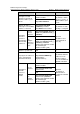
DHCP Configuration Examples H3C S7500 Series Ethernet Switches Release 3135 Chapter 1 DHCP Functions Overview Operation Command Description interface interface-type interface-number On one interface Configure a self-defined DHCP option dhcp server option code { ascii ascii-string | hex hex-string&<1-10> | ip-address ip-address&<1-8> } quit On multiple interfaces dhcp server option code { ascii ascii-string | hex hex-string&<1-10> | ip-address ip-address&<1-8> } { interface interface-type interface-n
DHCP Configuration Examples H3C S7500 Series Ethernet Switches Release 3135 Chapter 1 DHCP Functions Overview Table 1-3 Configure DHCP relay agent Operation Command Enter system view system-view Enable the DHCP service dhcp enable Configure DHCP server IP addresses for a DHCP server group dhcp-server groupNo ip ip-address&<1-8> Configure a DHCP user address entry dhcp-security static ip-address mac-address Enable the DHCP relay agent to support Option 82 dhcp relay information enable Configure
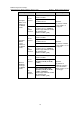
DHCP Configuration Examples H3C S7500 Series Ethernet Switches Release 3135 Chapter 1 DHCP Functions Overview Table 1-4 Configure DHCP snooping Operation Command Enter system view system-view Enable DHCP snooping dhcp-snooping Enable Option 82 support on the DHCP snooping device dhcp-snooping information enable Enter Ethernet port view interface interface-type interface-number Description — Required Specify the port connected to the DHCP server as a trusted port By default, DHCP snooping is di
DHCP Configuration Examples H3C S7500 Series Ethernet Switches Release 3135 Chapter 2 Configuration Examples Chapter 2 Configuration Examples 2.1 DHCP Server Configuration Example 2.1.1 Network Requirements An S7500 switch serves as the DHCP server in the corporate headquarters (HQ) to allocate IP addresses to the workstations in the HQ and Branch, and it also acts as the gateway to forward packets from the HQ.
DHCP Configuration Examples H3C S7500 Series Ethernet Switches Release 3135 Chapter 2 Configuration Examples 2.1.2 Network Diagram 10.214.10.5 10.214.10.3 10.214.10.4 002e-8d20-54c6 000d-85c7-4e20 0013-4ca8-9b71 Mail Server DNS Server VLAN-int10 IP network WINS Server DHCP Client HQ Gateway VLAN-int100 DHCP Relay DHCP Client1 DHCP Client2 File Server 10.210.10.4 000d-88f8-4e71 Branch Figure 2-1 Network diagram for DHCP server configuration 2.1.3 Configuration Procedure I.
DHCP Configuration Examples H3C S7500 Series Ethernet Switches Release 3135 Chapter 2 Configuration Examples No gateway needs to be configured for the clients because an interface operating in the interface address pool mode automatically serves as the gateway for DHCP clients and sends the requested information to the clients. # Assign IP addresses to the DNS server, WINS server, and mail server through IP-to-MAC bindings. [H3C-Vlan-interface10] dhcp server static-bind ip-address 10.214.10.
DHCP Configuration Examples H3C S7500 Series Ethernet Switches Release 3135 Chapter 2 Configuration Examples [H3C] dhcp server detect # Configure VLAN-interface100 to operate in the global address pool mode. [H3C] interface Vlan-interface 100 [H3C-Vlan-interface100] dhcp select global Note that: After DHCP configuration is complete, IP addresses can be assigned to the workstations in the Branch only when a route is active between the HQ and the Branch. II.
DHCP Configuration Examples H3C S7500 Series Ethernet Switches Release 3135 Chapter 2 Configuration Examples and the DHCP relay agent are interconnected through the 172.16.2.4/30 network segment. z Configure the address check function on the DHCP relay agent so that only the devices that are assigned legal IP addresses from the DHCP server are allowed to access the external network.
DHCP Configuration Examples H3C S7500 Series Ethernet Switches Release 3135 Chapter 2 Configuration Examples 2.2.3 Configuration Procedure I. Configuring the DHCP relay agent Figure 2-3 Network diagram for DHCP relay agent configuration # Configure to forward the DHCP requests from the Office to the DHCP server in the HQ. system-view [SwitchA] dhcp-server 1 ip 192.168.0.3 [SwitchA] interface vlan-interface10 [SwitchA-Vlan-interface10] ip address 192.168.10.
DHCP Configuration Examples H3C S7500 Series Ethernet Switches Release 3135 Chapter 2 Configuration Examples # Enable the DHCP relay agent to support DHCP Option 82 and adopt the strategy of keeping the original filed upon receiving DHCP messages carrying Option 82.
DHCP Configuration Examples H3C S7500 Series Ethernet Switches Release 3135 Chapter 2 Configuration Examples [LAB-Vlan-interface17] ip address 172.16.2.6 30 [LAB-Vlan-interface17] dhcp select global # Lab1 is connected to VLAN-interface15. Therefore, to assign the IP addresses in the 192.168.17.0/24 network segment to the devices in Lab1, you only need to configure VLAN-interface15 to operate in the interface address pool mode.
DHCP Configuration Examples H3C S7500 Series Ethernet Switches Release 3135 Chapter 2 Configuration Examples IV. Configuring the DHCP server in the HQ # On the H3C series switches, port numbers, VLAN numbers, and the MAC addresses of the DHCP snooping device and the DHCP relay agent are added to DHCP Option 82.
DHCP Configuration Examples H3C S7500 Series Ethernet Switches Release 3135 Chapter 2 Configuration Examples Note: The following configuration is performed on the Cisco Catalyst 3745 switch running IOS version 12.3(11)T2. If you are using any other models or devices running any other version, see the user manuals provided with the devices. # Enable DHCP server and allocate IP addresses using Option 82 information.
DHCP Configuration Examples H3C S7500 Series Ethernet Switches Release 3135 Chapter 2 Configuration Examples After the above-mentioned configuration, the DHCP server can automatically assign an IP address, the gateway address, DNS server address, and the WINS server address for each device in Office.
DHCP Configuration Examples H3C S7500 Series Ethernet Switches Release 3135 Chapter 3 Related Documents Chapter 3 Related Documents 3.
QACL Configuration Examples H3C S7500 Series Ethernet Switches Release 3135 Table of Contents Table of Contents Chapter 1 QACL Overview............................................................................................................ 1-1 1.1 QACL Support Matrix......................................................................................................... 1-1 1.2 Configuration Guide..........................................................................................................
QACL Configuration Examples H3C S7500 Series Ethernet Switches Release 3135 Abstract QACL Configuration Examples Keywords: ACL, QoS Abstract: This document introduces how QACL of the H3C series Ethernet switches is applied and configured in real network scenarios. In the document, time-based ACLs, line rates, traffic policing, traffic redirecting, traffic mirroring, traffic accounting, priority marking, queue scheduling, and flow-based selective QinQ are introduced.
QACL Configuration Examples H3C S7500 Series Ethernet Switches Release 3135 Chapter 1 QACL Overview Chapter 1 QACL Overview 1.1 QACL Support Matrix The LPUs of the S7500 series Ethernet switches fall into type-A LPUs and non-type-A LPUs. The following table describes different LPUs’ support for ACL/QoS functions.
QACL Configuration Examples H3C S7500 Series Ethernet Switches Release 3135 Chapter 1 QACL Overview 1.2 Configuration Guide Note: This guide provides only general configuration procedures. For detailed information about the involved functions and parameters, refer to the operation manual and command manual for your device. Follow these steps to configure ACL/QoS in system view: To do… Enter system view Configure an ACL Use the command...
QACL Configuration Examples H3C S7500 Series Ethernet Switches Release 3135 Chapter 1 QACL Overview Follow these steps to configure ACL/QoS in QoS view on a type-A LPU: To do… Use the command... Remarks Enter Ethernet port view interface interface-type interface-number — Enter QoS view qos — Configure packet filtering packet-filter { inbound | outbound } acl-rule [ system-index ] [ not-care-for-interface ] The acl-rule argument ranges from 2000 to 4999.
QACL Configuration Examples H3C S7500 Series Ethernet Switches Release 3135 To do… Chapter 1 QACL Overview Use the command... Remarks Configure traffic mirroring mirrored-to inbound acl-rule [ system-index ] { interface interface-type interface-number [ reflector ] | mirroring-group group-id } — Configure packet filtering packet-filter inbound acl-rule [ system-index ] The acl-rule argument ranges from 2000 to 5999.
QACL Configuration Examples H3C S7500 Series Ethernet Switches Release 3135 To do… Configure traffic accounting Chapter 1 QACL Overview Use the command... traffic-statistic inbound acl-rule [ system-index ] Remarks — Note that: Table 1-2 is the default 802.1p-precedence-to-local-precedence mapping table of z the S7500 series. Table 1-2 The default 802.1p-precedence-to-local-precedence mapping table 802.
QACL Configuration Examples H3C S7500 Series Ethernet Switches Release 3135 Chapter 1 QACL Overview Table 1-4 Non-type-A LPUs’ ways of applying combined ACLs Combination mode Form of acl-rule Apply all rules in an IP-based ACL (a basic ACL or advanced ACL) ip-group { acl-number | acl-name } Apply one rule in an IP-based ACL (a basic ACL or advanced ACL) ip-group { acl-number | acl-name } rule rule-id Apply all rules in a Layer-2 ACL link-group { acl-number | acl-name } Apply one rule in a Layer-2
QACL Configuration Examples H3C S7500 Series Ethernet Switches Release 3135 Chapter 2 QACL Configuration Examples Chapter 2 QACL Configuration Examples Note: Non-type-A LPUs are used in all configurations in this chapter.
QACL Configuration Examples H3C S7500 Series Ethernet Switches Release 3135 Chapter 2 QACL Configuration Examples 2.1 Configuration Examples in an Enterprise Network 192.168.5.1/24 192.168.5.2/24 192.168.2.1/24 GE2/0/10 192.168.2.2/24 GE2/0/1 GE2/0/7 GE2/0/2 GE2/0/3 GE2/0/4 GE2/0/6 192.168.5.3/24 GE2/0/5 192.168.4.2/24 192.168.4.1/24 192.168.3.
QACL Configuration Examples H3C S7500 Series Ethernet Switches Release 3135 Chapter 2 QACL Configuration Examples 2.1.1 Time-Based ACL and Traffic Accounting Configuration Example I. Network requirements In the R&D department, the IP address of PC 1 is 192.168.2.1 and that of PC 2 is 192.168.2.2. The gateway IP address is set to 192.168.2.100 (the IP address of VLAN-interface 2) for both PC 1 and PC 2.
QACL Configuration Examples H3C S7500 Series Ethernet Switches Release 3135 Chapter 2 QACL Configuration Examples [H3C-acl-adv-3000] rule 6 deny udp destination-port eq 137 [H3C-acl-adv-3000] rule 7 deny udp destination-port eq 138 [H3C-acl-adv-3000] rule 8 deny udp destination-port eq 139 [H3C-acl-adv-3000] rule 9 deny tcp destination-port eq 139 [H3C-acl-adv-3000] rule 10 deny tcp destination-port eq 445 [H3C-acl-adv-3000] rule 11 deny udp destination-port eq 445 [H3C-acl-adv-3000] rule 12 deny tcp dest
QACL Configuration Examples H3C S7500 Series Ethernet Switches Release 3135 Chapter 2 QACL Configuration Examples [H3C-GigabitEthernet2/0/1] quit # Configure traffic accounting on GigabitEthernet 2/0/2. [H3C] interface GigabitEthernet 2/0/2 [H3C-GigabitEthernet2/0/2] qos [H3C-qosb-GigabitEthernet2/0/2] traffic-statistic inbound ip-group 3001 2.1.2 Line Rate and Traffic Policing Configuration Example I. Network requirements In the customer service department, the IP address of PC 3 is 192.168.3.1.
QACL Configuration Examples H3C S7500 Series Ethernet Switches Release 3135 Chapter 2 QACL Configuration Examples [H3C] acl number 2000 [H3C-acl-basic-2000] rule permit source 192.168.3.1 0 [H3C-acl-basic-2000] quit # Configure traffic policing to limit the outbound traffic rate of PC 3 in the customer service department to 640 kbps and drop the exceeding traffic.
QACL Configuration Examples H3C S7500 Series Ethernet Switches Release 3135 Chapter 2 QACL Configuration Examples II. Network diagram Internet Switch GE2/0/6 GE2/0/5 GE2/0/4 PC 5 Data detect server 192.168.4.2/24 PC 4 192.168.4.1/24 Marketing department VLAN 4 Figure 2-4 Network diagram for traffic redirecting and traffic mirroring configuration III. Configuration procedure # Define the time range from 8:00 to 18:00 in working days.
QACL Configuration Examples H3C S7500 Series Ethernet Switches Release 3135 Chapter 2 QACL Configuration Examples # Configure traffic mirroring on GigabitEthernet 2/0/5 to mirror the Internet-accessing traffic from PC 5 to the data monitoring device.
QACL Configuration Examples H3C S7500 Series Ethernet Switches Release 3135 Chapter 2 QACL Configuration Examples [H3C] acl number 3000 [H3C-acl-adv-3000] rule 0 permit ip source 192.168.5.1 0 destination rule 1 permit ip source 192.168.5.2 0 destination rule 2 permit ip source 192.168.5.3 0 destination 129.110.1.2 0 [H3C-acl-adv-3000] 129.110.1.2 0 [H3C-acl-adv-3000] 129.110.1.
QACL Configuration Examples H3C S7500 Series Ethernet Switches Release 3135 Chapter 2 QACL Configuration Examples 2.
QACL Configuration Examples H3C S7500 Series Ethernet Switches Release 3135 z Chapter 2 QACL Configuration Examples VLAN 10 and VLAN 20 of the client-side network are connected to GigabitEthernet 2/0/1 of Switch A. In VLAN 20, there are some devices whose MAC addresses are in the range of 1234-5678-9000 to 1234-5678-90FF. z Packets of VLAN 10 and VLAN 20 in the client-side network arrive at GigabitEthernet 2/0/1 single-tagged. 2.2.1 Flow-Based Selective QinQ Configuration Example I.
QACL Configuration Examples H3C S7500 Series Ethernet Switches Release 3135 Chapter 2 QACL Configuration Examples # Configure GigabitEthernet 2/0/1 as a hybrid port and configure VLAN 100 as its default VLAN. Configure GigabitEthernet 2/0/1 to forward packets of VLAN 100 and VLAN 200 with the outer VLAN tag removed.
QACL Configuration Examples H3C S7500 Series Ethernet Switches Release 3135 Chapter 2 QACL Configuration Examples # Configure GigabitEthernet 2/0/1 as a hybrid port and configure VLAN 200 as its default VLAN. Configure GigabitEthernet 2/0/1 to forward packets of VLAN 200 with the outer VLAN tag removed.
QACL Configuration Examples H3C S7500 Series Ethernet Switches Release 3135 6) Chapter 2 QACL Configuration Examples The ACL rules configured for traffic policing, traffic redirecting, traffic mirroring, traffic accounting, priority marking, or flow-based selective QinQ must be permit statements. 7) On a non-type-A LPU, if a traffic policing rule is configured with the kbps keyword specified, the rate limit granularity is 64 kbps.
802.1x Configuration Examples H3C S7500 Series Ethernet Switches Release 3135 Table of Contents Table of Contents Chapter 1 802.1X Overview .......................................................................................................... 1-1 1.1 Introduction to 802.1X........................................................................................................ 1-1 1.2 Features Configuration .................................................................................................
802.1x Configuration Examples H3C S7500 Series Ethernet Switches Release 3135 Abstract 802.1x Configuration Example Keywords: 802.1x and AAA Abstract: This article introduces the application of 802.1x on Ethernet switches in real network environments, and then presents detailed configurations of the 802.1x client, LAN Switch and AAA server respectively.
802.1x Configuration Examples H3C S7500 Series Ethernet Switches Release 3135 Chapter 1 802.1X Overview Chapter 1 802.1X Overview Note: The use of this document is restricted to H3C S7500 Series Ethernet switches. 1.1 Introduction to 802.1X The LAN defined in IEEE 802 protocols does not provide access authentication. In general, users can access network devices or resources in a LAN as long as they access the LAN.
802.1x Configuration Examples H3C S7500 Series Ethernet Switches Release 3135 Chapter 1 802.1X Overview 1.2.3 Precautions z The configuration of dot1x on a specific port takes effect only after the dot1x feature is enabled globally and on the port. z You can configure dot1x parameters associated with Ethernet ports or devices before enabling dot1x. However, the configured dot1x parameters only take effect after dot1x is enabled.
802.1x Configuration Examples H3C S7500 Series Ethernet Switches Release 3135 Chapter 2 802.1X Configuration Commands Chapter 2 802.1X Configuration Commands To implement 802.1x, you need to configure the supplicant system (client), authenticator system (switch) and authentication/authorization server correctly. z Supplicant system: Ensures that the PC uses a right client. z Authenticator system: Configuring 802.1x and AAA on the authenticator system is required.
802.1x Configuration Examples H3C S7500 Series Ethernet Switches Release 3135 Chapter 3 Enterprise Network Access Authentication Configuration Example Chapter 3 Enterprise Network Access Authentication Configuration Example Note: The configuration or information displayed may vary with devices. The following takes the H3C S7500 series switch (using software Release 3135) as an example. 3.
802.1x Configuration Examples H3C S7500 Series Ethernet Switches Release 3135 Chapter 3 Enterprise Network Access Authentication Configuration Example 3.2 Network Diagram Figure 3-1 Network diagram for enterprise network application 3.3 Configuration Procedure 3.3.1 Configuring the Switch # Create a RADIUS scheme named “cams”, and specify the primary and secondary authentication/accounting servers. system-view [H3C] radius scheme cams [H3C-radius-cams] primary authentication 192.168.1.
802.1x Configuration Examples H3C S7500 Series Ethernet Switches Release 3135 Chapter 3 Enterprise Network Access Authentication Configuration Example # Create an ISP domain named “abc” and adopt the RADIUS scheme “cams” for authentication. [H3C] domain abc [H3C-isp-abc] radius-scheme cams # Set the dynamic VLAN assignment mode. [H3C-isp-abc] vlan-assignment-mode integer [H3C-isp-abc] quit # Set the ISP domain “abc” as the default ISP domain.
802.1x Configuration Examples H3C S7500 Series Ethernet Switches Release 3135 Chapter 3 Enterprise Network Access Authentication Configuration Example 802.
802.1x Configuration Examples H3C S7500 Series Ethernet Switches Release 3135 Chapter 3 Enterprise Network Access Authentication Configuration Example RADIUS Scheme = cams Access-limit = Disable Vlan-assignment-mode = Integer accounting-mode = time Domain User Template: Idle-cut = Disable Self-service = Disable Messenger Time = Disable 3.3.
802.1x Configuration Examples H3C S7500 Series Ethernet Switches Release 3135 2) Chapter 3 Enterprise Network Access Authentication Configuration Example After login, the following page appears: Figure 3-3 CAMS configuration console II. Creating an accounting policy 1) Enter the Accounting Policy Management page. Log in the CAMS configuration console. On the navigation tree, select Charges Management > Accounting Policy to enter the Accounting Policy Management page, as shown in Figure 3-4.
802.1x Configuration Examples H3C S7500 Series Ethernet Switches Release 3135 Chapter 3 Enterprise Network Access Authentication Configuration Example Figure 3-5 Accounting Policy Basic Information 3) Click Next to enter the Accounting Attribute Settings page, and set Accounting Type to By duration, Monthly Cycle to Monthly and Monthly Fixed Fee to 50 dollars, as shown in Figure 3-6. Figure 3-6 Accounting Attribute Settings Click OK. A monthly payment accounting policy is created. III.
802.1x Configuration Examples H3C S7500 Series Ethernet Switches Release 3135 Chapter 3 Enterprise Network Access Authentication Configuration Example z Service Name: abc z Service Suffix Name: abc z Accounting Policy: Monthly Fixed Payment z Upstream Rate Limitation: 2M (2048 Kbps) z Downstream Rate Limitation: 2M (2048 Kbps) z VLAN Assignment: VLAN 100 z Authentication Binding: Bind user IP address and bind user MAC address Figure 3-8 Add Service Click OK. A service type is added. IV.
802.1x Configuration Examples H3C S7500 Series Ethernet Switches Release 3135 2) Chapter 3 Enterprise Network Access Authentication Configuration Example Add an account user. Click Add to enter the Add Account page and configure as follows: z Account: info z Password: info z Full Name: Bruce z Prepaid Money: 100 dollars z Bind multiple IP address and MAC address: enable z Online Limit: 1 z Max. Idle Time: 20 minutes z Service Information: abc Figure 3-10 Add Account Click OK.
802.1x Configuration Examples H3C S7500 Series Ethernet Switches Release 3135 Chapter 3 Enterprise Network Access Authentication Configuration Example Figure 3-11 System Configuration 2) Click the Modify link for the Access Device item to enter the Access Device Configuration page to modify access device configuration like IP address, shared key, and authentication and accounting ports. Figure 3-12 Access Device Configuration VI.
802.1x Configuration Examples H3C S7500 Series Ethernet Switches Release 3135 2) Chapter 3 Enterprise Network Access Authentication Configuration Example Click OK. The prompt page appears as shown in Figure 3-14. Figure 3-14 Page prompting that system configuration is modified successfully 3) Return to the System Configuration page and click Validate Now to make the configuration take effect immediately. Figure 3-15 Validate Now on System Management page 3.3.
802.1x Configuration Examples H3C S7500 Series Ethernet Switches Release 3135 Chapter 3 Enterprise Network Access Authentication Configuration Example I. Starting up H3C iNode intelligent client Figure 3-16 H3C iNode intelligent client II. Creating a connection To create a connection, follow the steps below: 1) Click the New Connection link in the left pane of the client interface to launch the Create New Connection Wizard dialog box. 2) Click Next in the wizard dialog box, and then select 802.
802.1x Configuration Examples H3C S7500 Series Ethernet Switches Release 3135 Chapter 3 Enterprise Network Access Authentication Configuration Example Figure 3-17 Create an 802.1x connection 5) Enter a connection name, username and password, and check/uncheck the Save password checkbox as required. 6) Click Next to enter the Network Property Settings page, as shown in Figure 3-18, to configure the connection attributes.
802.1x Configuration Examples H3C S7500 Series Ethernet Switches Release 3135 Chapter 3 Enterprise Network Access Authentication Configuration Example Figure 3-18 Set special properties 7) Keep the default settings and click OK, and then click Create after confirming the settings. The connection is created and the connection icon is displayed on the client interface. III.
802.1x Configuration Examples H3C S7500 Series Ethernet Switches Release 3135 Chapter 3 Enterprise Network Access Authentication Configuration Example Figure 3-19 Connection dialog box The connection is established after successful authentication. 3.3.4 Verifying Configuration To verify that the configuration of Guest VLAN is taking effect, check that users can access VLAN 10 before 802.1x authentication or the 802.1x authentication fails.
802.1x Configuration Examples H3C S7500 Series Ethernet Switches Release 3135 z Chapter 3 Enterprise Network Access Authentication Configuration Example Use the debugging dot1x packet command to verify that the switch receives and sends EAP packets and EAPoL frames normally. II. Symptom: Users can access network resources without 802.1x authentication z Use the display dot1x command to verify 802.1x is enabled globally and on the specified ports.
SSH Configuration Examples H3C S7500 Series Ethernet Switches Release 3135 Table of Contents Table of Contents Chapter 1 SSH Overview .............................................................................................................. 1-1 1.1 Introduction to SSH............................................................................................................ 1-1 1.2 Support for SSH Functions ...............................................................................................
SSH Configuration Examples H3C S7500 Series Ethernet Switches Release 3135 Abstract SSH Configuration Example Keywords: SSH, RSA Abstract: This article introduces the application of SSH on the H3C S7500 series Ethernet switches in real network environments, and then presents detailed configurations of the involved SSH client and Ethernet switches respectively.
SSH Configuration Examples H3C S7500 Series Ethernet Switches Release 3135 Chapter 1 SSH Overview Chapter 1 SSH Overview 1.1 Introduction to SSH Secure Shell (SSH) is designed to provide secure remote login and other security services in insecure network environments.
SSH Configuration Examples H3C S7500 Series Ethernet Switches Release 3135 Chapter 1 SSH Overview II. For a non H3C device to be the SSH server For such configuration, refer to the related user manual. 1.3.2 Configuring an SSH Client I. Using SSH client software There are many kinds of SSH client software, such as PuTTY and OpenSSH. You can select one as required and refer to the attached manual for configuration. II.
SSH Configuration Examples H3C S7500 Series Ethernet Switches Release 3135 Chapter 2 SSH Configuration Commands Chapter 2 SSH Configuration Commands 2.1 SSH Configuration Commands To implement SSH, you need to configure the SSH client and the SSH server correctly. The subsequent sections describe SSH configuration commands on the switch. For more information, refer to the SSH Operation Manual. 2.2 Configuring an H3C Switch as an SSH Server 2.2.
SSH Configuration Examples H3C S7500 Series Ethernet Switches Release 3135 z Chapter 2 SSH Configuration Commands Executing the ssh authentication-type default all command or the ssh user authentication-type all command means that users can login the SSH server as long as they pass either the password or RSA authentication. II. Public key configuration procedure and precautions As shown in Table 2-1, you need to copy or import the public key from the client to the server.
SSH Configuration Examples H3C S7500 Series Ethernet Switches Release 3135 Operation Chapter 2 SSH Configuration Commands Command Remarks Optional Set SSH authentication timeout time ssh server timeout seconds Set SSH authentication retry times ssh server authentication-retries times Set RSA server key update interval ssh server rekey-interval hours By default, the timeout time is 60 seconds. Optional By default, the number of retry times is 3.
SSH Configuration Examples H3C S7500 Series Ethernet Switches Release 3135 Chapter 2 SSH Configuration Commands III. Configuring the client RSA public key manually Table 2-4 Configure the client RSA public key manually Operation Command Specify the default authentication type for all SSH users Create an SSH user and specify an authentication type Create an SSH user, and specify an authentication type for it Description ssh authenticatio n-type default rsa Use either command.
SSH Configuration Examples H3C S7500 Series Ethernet Switches Release 3135 Chapter 2 SSH Configuration Commands Note: For common configuration commands, refer to Table 2-2. 2.3 Configuring an H3C Switch as an SSH Client When the device connects to the SSH server as an SSH client, you can configure whether the device supports first-time authentication.
SSH Configuration Examples H3C S7500 Series Ethernet Switches Release 3135 Chapter 2 SSH Configuration Commands As shown in Table 2-5, you need to configure the server public key to the client in the case that the SSH client does not support first-time authentication. z On the SSH server, use the display rsa local-key-pair public command to display the RSA public key. z Configure the public key to the SSH client.
SSH Configuration Examples H3C S7500 Series Ethernet Switches Release 3135 Operation Chapter 2 SSH Configuration Commands Command Description Enter the content of the public key When you input the key data, spaces are allowed between the characters you input (because the system can remove the spaces automatically); you can also press to continue your input at the next line. But the key you input should be a hexadecimal digit string coded in the public key format.
SSH Configuration Examples H3C S7500 Series Ethernet Switches Release 3135 Chapter 3 SSH Configuration Examples Chapter 3 SSH Configuration Examples Note: The S7500 software version in this configuration example is Release 3135. 3.1 SSH Configuration Examples 3.1.1 When the Switch Acts as the SSH Server and the Authentication Type is Password I. Network requirements As shown in Figure 3-1, establish an SSH connection between the host (SSH Client) and the switch (SSH Server) for secure data exchange.
SSH Configuration Examples H3C S7500 Series Ethernet Switches Release 3135 Chapter 3 SSH Configuration Examples The range of public key size is (512 ~ 2048). NOTES: If the key modulus is greater than 512, It will take a few minutes. Input the bits in the modulus[default = 1024]: Generating keys... ..............++++++ ............................++++++ ...........................................++++++++ .................++++++++ ......... # Set the authentication mode for the user interface to AAA.
SSH Configuration Examples H3C S7500 Series Ethernet Switches Release 3135 Chapter 3 SSH Configuration Examples Figure 3-2 SSH client configuration interface In the Host Name (or IP address) text box, enter the IP address of the SSH server. z From the category on the left pane of the window, select SSH under Connection. The window as shown in Figure 3-3 appears.
SSH Configuration Examples H3C S7500 Series Ethernet Switches Release 3135 Chapter 3 SSH Configuration Examples Figure 3-3 SSH client configuration interface 2 Under Protocol options, select 2 from Preferred SSH protocol version. z As shown in Figure 3-4, click Open to enter the following interface. If the connection is normal, you will be prompted to enter the user name “client001” and password “abc”. Once authentication succeeds, you will log onto the server.
SSH Configuration Examples H3C S7500 Series Ethernet Switches Release 3135 Chapter 3 SSH Configuration Examples Figure 3-4 SSH client interface 3.1.2 When the Switch Acts as an SSH Server and the Authentication Type is RSA I. Network requirements As shown in Figure 3-5, establish an SSH connection between the host (SSH client) and the switch (SSH Server) for secure data exchange. The host runs SSH2.0 client software. RSA authentication is required. II.
SSH Configuration Examples H3C S7500 Series Ethernet Switches Release 3135 Chapter 3 SSH Configuration Examples [H3C-Vlan-interface1] quit # Generate an RSA key pair. [H3C] rsa local-key-pair create # Set the authentication mode for the user interface to AAA. [H3C] user-interface vty 0 4 [H3C-ui-vty0-4] authentication-mode scheme # Enable the user interface to support SSH.
SSH Configuration Examples H3C S7500 Series Ethernet Switches Release 3135 z Chapter 3 SSH Configuration Examples Run PuTTYGen.exe, choose SSH-2 RSA and click Generate. Figure 3-6 Generate a client key pair (1) Note: While generating the key pair, you must move the mouse continuously and keep the mouse off the green process bar shown in Figure 3-7. Otherwise, the process bar stops moving and the key pair generating process is stopped.
SSH Configuration Examples H3C S7500 Series Ethernet Switches Release 3135 Chapter 3 SSH Configuration Examples Figure 3-7 Generate a client key pair (2) After the key pair is generated, click Save public key and enter the name of the file for saving the public key (“public” in this case).
SSH Configuration Examples H3C S7500 Series Ethernet Switches Release 3135 Chapter 3 SSH Configuration Examples Figure 3-8 Generate a client key pair (3) Likewise, to save the private key, click Save private key. A warning window pops up to prompt you whether to save the private key without any protection. Click Yes and enter the name of the file for saving the private key (“private.ppk” in this case). Figure 3-9 Generate a client key pair (4) z Run SSHKEY.
SSH Configuration Examples H3C S7500 Series Ethernet Switches Release 3135 Chapter 3 SSH Configuration Examples Figure 3-10 Generate a client key pair (5) Note: After the public key is converted to the PKCS format, you need to manually configure the RSA public key in the PKCS format on the server, and complete the server end configuration before continuing to configure the client. # Establish a connection with the SSH server. The following takes the SSH client software Putty (version 0.
SSH Configuration Examples H3C S7500 Series Ethernet Switches Release 3135 Chapter 3 SSH Configuration Examples Figure 3-11 SSH client configuration interface 1 In the Host Name (or IP address) text box, enter the IP address of the server. z From the category on the left pane of the window, select SSH under Connection. The window as shown in Figure 3-12appears.
SSH Configuration Examples H3C S7500 Series Ethernet Switches Release 3135 Chapter 3 SSH Configuration Examples Figure 3-12 SSH client configuration interface 2 Under Protocol options, select 2 from Preferred SSH protocol version. z Select Connection > SSH > Auth. The following window appears.
SSH Configuration Examples H3C S7500 Series Ethernet Switches Release 3135 Chapter 3 SSH Configuration Examples Figure 3-13 SSH client configuration interface (2) Click Browse… to bring up the file selection window, navigate to the private key file and click OK. z From the window shown in Figure 3-13, click Open. The following SSH client interface appears. If the connection is normal, you will be prompted to enter the username and password, as shown in Figure 3-14.
SSH Configuration Examples H3C S7500 Series Ethernet Switches Release 3135 Chapter 3 SSH Configuration Examples Figure 3-14 SSH client interface 3.1.3 When the Switch Acts as an SSH Client and the Authentication Type is Password I. Network requirements As shown in Figure 3-15, establish an SSH connection between Switch A (SSH Client) and Switch B (SSH Server) for secure data exchange. The user name for login is client001 and the SSH server’s IP address is 10.165.87.136.
SSH Configuration Examples H3C S7500 Series Ethernet Switches Release 3135 Chapter 3 SSH Configuration Examples system-view [H3C] interface vlan-interface 1 [H3C-Vlan-interface1] ip address 10.165.87.136 255.255.255.0 [H3C-Vlan-interface1] quit # Generate an RSA key pair. [H3C] rsa local-key-pair create # Set the authentication mode for the user interface to AAA. [H3C] user-interface vty 0 4 [H3C-ui-vty0-4] authentication-mode scheme # Enable the user interface to support SSH.
SSH Configuration Examples H3C S7500 Series Ethernet Switches Release 3135 Chapter 3 SSH Configuration Examples Trying 10.165.87.136 ... Press CTRL+K to abort Connected to 10.165.87.136 ... The Server is not authenticated. Do you continue to access it?(Y/N):y Do you want to save the server's public key?(Y/N):n Enter password: ******************************************************************* * Copyright (c) 2004-2007 Hangzhou H3C Technologies Co., Ltd.
SSH Configuration Examples H3C S7500 Series Ethernet Switches Release 3135 Chapter 3 SSH Configuration Examples # Set the authentication mode for the user interfaces to AAA. [H3C] user-interface vty 0 4 [H3C-ui-vty0-4] authentication-mode scheme # Enable the user interfaces to support SSH. [H3C-ui-vty0-4] protocol inbound ssh # Set the user command privilege level to 3. [H3C-ui-vty0-4] user privilege level 3 [H3C-ui-vty0-4] quit # Specify the authentication type of user “client001” as RSA.
SSH Configuration Examples H3C S7500 Series Ethernet Switches Release 3135 2) Chapter 3 SSH Configuration Examples Configure Switch A # Create a VLAN interface on the switch and assign an IP address, which serves as the SSH client’s address in an SSH connection. system-view [H3C] interface vlan-interface 1 [H3C-Vlan-interface1] ip address 10.165.87.137 255.255.255.0 [H3C-Vlan-interface1] quit # Generate an RSA key pair [H3C] rsa local-key-pair create # Display the RSA public key on the client.
SSH Configuration Examples H3C S7500 Series Ethernet Switches Release 3135 Chapter 3 SSH Configuration Examples Connected to 10.165.87.136 ... The Server is not authenticated. Do you continue to access it?(Y/N):y Do you want to save the server's public key?(Y/N):n ******************************************************************* * Copyright (c) 2004-2007 Hangzhou H3C Technologies Co., Ltd. * * Without the owner's prior written consent, * * no decompiling or reverse-engineering shall be allowed.
SSH Configuration Examples H3C S7500 Series Ethernet Switches Release 3135 Chapter 3 SSH Configuration Examples [H3C] user-interface vty 0 4 [H3C-ui-vty0-4] authentication-mode scheme # Enable the user interfaces to support SSH. [H3C-ui-vty0-4] protocol inbound ssh # Set the user command privilege level to 3. [H3C-ui-vty0-4] user privilege level 3 [H3C-ui-vty0-4] quit # Specify the authentication type for user “client001” as RSA.
SSH Configuration Examples H3C S7500 Series Ethernet Switches Release 3135 Chapter 3 SSH Configuration Examples Note: If first-time authentication is disabled on the device, it is necessary to configure on the SSH client the RSA public key of the SSH server. # Display the RSA public key on the server.
SSH Configuration Examples H3C S7500 Series Ethernet Switches Release 3135 Chapter 3 SSH Configuration Examples Key name: H3C_Host Key type: RSA encryption Key ===================================================== Key code: 3047 0240 C8969B5A 132440F4 0BDB4E5E 40308747 804F608B 349EBD6A B0C75CDF 8B84DBE7 D5E2C4F8 AED72834 74D3404A 0B14363D D709CC63 68C8CE00 57C0EE6B 074C0CA9 0203 010001 Note: After the SSH client generates an RSA key pair, it is necessary to configure the RSA public key on the
SSH Configuration Examples H3C S7500 Series Ethernet Switches Release 3135 Chapter 3 SSH Configuration Examples [H3C-rsa-key-code] 5C3615C3 E5B3DC91 D41900F0 2AE8B301 E55B1420 [H3C-rsa-key-code] 024ECF2C 28A6A454 C27449E0 46EB1EAF 8A918D33 [H3C-rsa-key-code] BAF53AF3 63B1FB17 F01E4933 00BE2EEA A272CD78 [H3C-rsa-key-code] C289B7DD 2BE0F7AD [H3C-rsa-key-code] 0203 [H3C-rsa-key-code] 010001 [H3C-rsa-key-code] public-key-code end [H3C-rsa-public-key] peer-public-key end [H3C] # Specify the host public key na
Routing Configuration Examples H3C S7500 Series Ethernet Switches Release 3135 Table of Contents Table of Contents Chapter 1 Routing Overview ........................................................................................................ 1-1 1.1 Overview ............................................................................................................................ 1-1 1.1.1 Static Routing and Routing Protocols .....................................................................
Routing Configuration Examples H3C S7500 Series Ethernet Switches Release 3135 Table of Contents 3.3.1 Displaying the Whole Configuration on Devices ................................................... 3-20 3.4 Verifying the Configuration .............................................................................................. 3-31 3.4.1 Verifying the Configuration of Routing Policy and Static Routes .......................... 3-31 3.4.2 Verifying the BGP and IGP Interaction Configuration ............
Routing Configuration Examples H3C S7500 Series Ethernet Switches Release 3135 Abstract Routing Configuration Example Keywords: Static routing, RIP, OSPF, ISIS, BGP Abstract: This document describes the IPv4 routing protocols that the H3C S7500 series support and the corresponding network configurations.
Routing Configuration Examples H3C S7500 Series Ethernet Switches Release 3135 Chapter 1 Routing Overview Chapter 1 Routing Overview 1.1 Overview 1.1.1 Static Routing and Routing Protocols I. Static routing Static routing features zero overhead, simple configuration, and is applicable to simple and stable networks. But it requires human intervention when the network topology changes. II.
Routing Configuration Examples H3C S7500 Series Ethernet Switches Release 3135 Chapter 1 Routing Overview 1.2 Configuration Guide Note: z This configuration guide takes S7500 series Ethernet switches as an example. z For configuration precautions, see corresponding operation manuals and command manuals. 1.2.1 Configuration Task List Table 1-1 Configuration task List Task Details Static route configuration 1.2.2 RIP configuration 1.2.3 OSPF configuration 1.2.4 ISIS Configuration 1.2.
Routing Configuration Examples H3C S7500 Series Ethernet Switches Release 3135 Chapter 1 Routing Overview 1.2.
Routing Configuration Examples H3C S7500 Series Ethernet Switches Release 3135 Chapter 1 Routing Overview II.
Routing Configuration Examples H3C S7500 Series Ethernet Switches Release 3135 Operation Chapter 1 Routing Overview Command Set the additional routing metric to be added for incoming RIP routes on this interface Set the additional routing metric to be added for outgoing RIP routes on this interface Remarks Optional rip metricin value By default, the additional routing metric added for incoming routes on an interface is 0.
Routing Configuration Examples H3C S7500 Series Ethernet Switches Release 3135 Operation Configure RIP to filter incoming routes Chapter 1 Routing Overview Command Remarks filter-policy { acl-number | ip-prefix ip-prefix-name [ gateway ip-prefix-name ] | gateway ip-prefix-name } import [ interface interface-type interface-number ] filter-policy gateway ip-prefix-name import Configure RIP to filter outgoing routes filter-policy { acl-number | ip-prefix ip-prefix-name } export [ protocol [ process-id
Routing Configuration Examples H3C S7500 Series Ethernet Switches Release 3135 Chapter 1 Routing Overview X.
Routing Configuration Examples H3C S7500 Series Ethernet Switches Release 3135 Chapter 1 Routing Overview XIII. Configuring RIP-1 packet zero field check Table 1-16 Configure RIP-1 packet zero field check Operation Command Remarks Enter system view system-view — Enter RIP view rip — Enable the check of the “must be zero” field in RIP-1 packets checkzero Required Enabled by default. XIV.
Routing Configuration Examples H3C S7500 Series Ethernet Switches Release 3135 Chapter 1 Routing Overview 1.2.
Routing Configuration Examples H3C S7500 Series Ethernet Switches Release 3135 Operation Chapter 1 Routing Overview Command Remarks Optional If multiple OSPF processes run on a router, you are recommended to use the router-id keyword in the ospf command to specify different router IDs for different processes.
Routing Configuration Examples H3C S7500 Series Ethernet Switches Release 3135 Operation Create and configure a virtual link Chapter 1 Routing Overview Command vlink-peer router-id [ hello seconds | retransmit seconds | trans-delay seconds | dead seconds | simple password | md5 keyid key ] * Remarks Optional For a virtual link to take effect, you need to use this command at both ends of the virtual link and ensure consistent configurations of the hello, dead, and other parameters at both ends. III.
Routing Configuration Examples H3C S7500 Series Ethernet Switches Release 3135 Chapter 1 Routing Overview V. Configuring the DR Priority on an OSPF Interface Table 1-24 Configure the DR priority on an OSPF interface Operation Command Remarks Enter system view system-view — Enter interface view interface interface-type interface-number — Configure the DR priority on the OSPF interface ospf dr-priority priority Optional The default DR priority is 1. VI.
Routing Configuration Examples H3C S7500 Series Ethernet Switches Release 3135 Chapter 1 Routing Overview VII.
Routing Configuration Examples H3C S7500 Series Ethernet Switches Release 3135 Chapter 1 Routing Overview X.
Routing Configuration Examples H3C S7500 Series Ethernet Switches Release 3135 Operation Chapter 1 Routing Overview Command Remarks Optional Configure the hello interval on the interface ospf timer hello seconds By default, p2p and broadcast interfaces send Hello packets every 10 seconds; while p2mp and NBMA interfaces send Hello packets every 30 seconds. Optional Configure the poll interval on the NBMA interface ospf timer poll seconds By default, poll packets are sent every 40 seconds.
Routing Configuration Examples H3C S7500 Series Ethernet Switches Release 3135 Chapter 1 Routing Overview XIII. Configuring the SPF Calculation Interval Table 1-33 Configure the SPF calculation interval Operation Command Remarks Enter system view system-view — Enter OSPF view ospf [ process-id [ router-id router-id ] ] — Configure the SPF calculation interval spf-schedule-interval interval Optional By default, the SPF calculation interval is five seconds. XIV.
Routing Configuration Examples H3C S7500 Series Ethernet Switches Release 3135 Operation Chapter 1 Routing Overview Command ospf authentication-mode { simple password | md5 key-id key } Configure the authentication mode of the OSPF interface Remarks Optional By default, OSPF packets are not authenticated on an interface. XVI.
Routing Configuration Examples H3C S7500 Series Ethernet Switches Release 3135 Chapter 1 Routing Overview 1.2.
Routing Configuration Examples H3C S7500 Series Ethernet Switches Release 3135 Chapter 1 Routing Overview I. Enabling IS-IS Table 1-39 Enable IS-IS Operation Command Enter system view system-view Enable IS-IS isis [ tag ] Remarks — Required Disabled by default II.
Routing Configuration Examples H3C S7500 Series Ethernet Switches Release 3135 Chapter 1 Routing Overview V. Configuring the IS Level Table 1-43 Configure the IS Level Operation Command Remarks Enter system view system-view — Enter IS-IS view isis [ tag ] — Configure the IS Level is-level { level-1 | level-1-2 | level-2 } Required level-1-2 by default. VI.
Routing Configuration Examples H3C S7500 Series Ethernet Switches Release 3135 Chapter 1 Routing Overview VIII. Configuring IS-IS Route Filtering Table 1-46 Configure incoming route filtering Operation Command Remarks Enter system view system-view — Enter IS-IS view isis [ tag ] — Configure incoming route filtering filter-policy acl-number import Required Not configured by default.
Routing Configuration Examples H3C S7500 Series Ethernet Switches Release 3135 Chapter 1 Routing Overview XI. Enabling Default Route Advertisement Table 1-50 Enable default route advertisement Operation Command Remarks Enter system view system-view — Enter IS-IS view isis [ tag ] — Enable default route advertisement default-route-advertise [ route-policy route-policy-name ] Required Only the same level routers can accept the default route. XII.
Routing Configuration Examples H3C S7500 Series Ethernet Switches Release 3135 Chapter 1 Routing Overview Operation Specify a cost for the interface Command Remarks Required isis cost value [ level-1 | level-2 ] 10 by default. XV.
Routing Configuration Examples H3C S7500 Series Ethernet Switches Release 3135 Chapter 1 Routing Overview Table 1-57 Specify the interval for retransmitting an LSP for an interface Operation Command Remarks Enter system view system-view — Enter interface view interface interface-type interface-number — Specify the interval for retransmitting an LSP on a P2P link Required isis timer retransmit seconds 5 seconds by default.
Routing Configuration Examples H3C S7500 Series Ethernet Switches Release 3135 Chapter 1 Routing Overview Operation Configure the routing domain authentication mode and password Command Remarks Optional domain-authentication-mode { simple | md5 } password [ ip | osi ] Not configured by default.
Routing Configuration Examples H3C S7500 Series Ethernet Switches Release 3135 Chapter 1 Routing Overview XIX. Configuring IS-IS to Discard Checksum Error LSPs Table 1-64 Configure IS-IS to discard checksum error LSPs Operation Command Remarks Enter system view system-view — Enter IS-IS view isis [ tag ] — Configure IS-IS to discard checksum error LSPs ignore-lsp-checksum-error Required By default, ISIS ignores checksum error LSPs. XX.
Routing Configuration Examples H3C S7500 Series Ethernet Switches Release 3135 Chapter 1 Routing Overview Operation Configure the LSP age Command Remarks Required timer lsp-max-age seconds 1200 seconds by default. XXIII. Configure SPF Parameters Table 1-68 Specify the SPF calculation interval Operation Command Remarks Enter system view system-view — Enter IS-IS view isis [ tag ] — Specify the SPF calculation interval timer spf seconds [ level-1 | level-2 ] Required 10 seconds by default.
Routing Configuration Examples H3C S7500 Series Ethernet Switches Release 3135 Chapter 1 Routing Overview XXIV. Disabling an Interface from Sending ISIS Packets Table 1-71 Disable an interface from sending ISIS packets Operation Command Remarks Enter system view system-view — Enter IS-IS view isis [ tag ] — Disable an interface from sending ISIS packets silent-interface interface-type interface-number Required Enabled by default. 1.2.
Routing Configuration Examples H3C S7500 Series Ethernet Switches Release 3135 Chapter 1 Routing Overview I. Configuring Basic BGP Functions Table 1-73 Configure basic BGP functions Operation Command Description Enter system view system-view — Enable BGP and enter BGP view bgp as-number By default, BGP is disabled. Specify the AS number for the BGP peers peer group-name as-number as-number By default, a peer is not assigned an AS number.
Routing Configuration Examples H3C S7500 Series Ethernet Switches Release 3135 Operation Chapter 1 Routing Overview Command Description Optional Import the default route to the BGP routing table default-route imported Import and advertise routing information generated by other protocols.
Routing Configuration Examples H3C S7500 Series Ethernet Switches Release 3135 Operation Chapter 1 Routing Overview Command Description Required Enable default route advertising peer group-name default-route-advertise By default, a BGP router does not send default routes to a specified peer/peer group. V.
Routing Configuration Examples H3C S7500 Series Ethernet Switches Release 3135 Chapter 1 Routing Overview VI.
Routing Configuration Examples H3C S7500 Series Ethernet Switches Release 3135 Chapter 1 Routing Overview VIII. Configuring BGP Load Balancing Table 1-80 Configure BGP load balancing Operation Command Description Enter system view system-view — Enter BGP view bgp as-number — Configure the maximum number of equal cost BGP routes for load balancing balance num Required By default, no load balancing is configured. IX.
Routing Configuration Examples H3C S7500 Series Ethernet Switches Release 3135 Operation Set the default local preference Configure the default local MED value Configure the MED attribute Permit to compare the MED values of the routes coming from the neighbor routers in different ASs. Chapter 1 Routing Overview Command default local-preference value default med med-value Description Optional By default, the local preference defaults to 100. Optional By default, the med-value argument is 0.
Routing Configuration Examples H3C S7500 Series Ethernet Switches Release 3135 Chapter 1 Routing Overview XI. Adjusting and Optimizing a BGP Network Table 1-83 Adjust and optimize a BGP network Operation Command Description Enter system view system-view — Enter BGP view bgp as-number — Configure BGP timer Configure the Keepalive time and Holdtime of BGP. timer keepalive keepalive-interval hold holdtime-interval Configure the Keepalive time and holdtime of a specified peer/peer group.
Routing Configuration Examples H3C S7500 Series Ethernet Switches Release 3135 Chapter 1 Routing Overview XII.
Routing Configuration Examples H3C S7500 Series Ethernet Switches Release 3135 Operation Chapter 1 Routing Overview Command Description Required Configure the peers to advertise community attribute to each other peer group-name advertise-community Specify routing policy for the routes exported to the peer group peer group-name route-policy route-policy-name export By default, no community attribute or extended community attribute is advertised to any peer group.
Routing Configuration Examples H3C S7500 Series Ethernet Switches Release 3135 Chapter 1 Routing Overview Operation Basic BGP confederation configuration Command Configure confederation ID confederation id as-number Specify the sub-ASs included in a confederation confederation peer-as as-number-list Configure the compatibility of a confederation confederation { nonstandard | standard1965 | standard3065 } Description Required By default, no confederation ID is configured and no sub-AS is configure
Routing Configuration Examples H3C S7500 Series Ethernet Switches Release 3135 Chapter 1 Routing Overview II. Configuring an AS Path List Table 1-90 AS path list configuration Operation Command Description Enter system view system-view — Optional Configure AS path list ip as-path-acl acl-number { permit | deny } as-regular-expression By default, no AS path list is defined III.
Routing Configuration Examples H3C S7500 Series Ethernet Switches Release 3135 Chapter 1 Routing Overview V.
Routing Configuration Examples H3C S7500 Series Ethernet Switches Release 3135 Chapter 1 Routing Overview VI.
Routing Configuration Examples H3C S7500 Series Ethernet Switches Release 3135 Chapter 2 Configuration Examples Chapter 2 Configuration Examples Note: The following configuration examples use the S7500 series switches. 2.1 Configuration Examples 2.1.1 Static Routing Configuration Example I. Network requirements 1) Requirement analysis: A small company requires any two nodes in its network communicate with each other. The network should be simple and stable.
Routing Configuration Examples H3C S7500 Series Ethernet Switches Release 3135 Chapter 2 Configuration Examples II. Configuration procedure Configure the switches: # Configure static routes on Switch A. system-view [SwitchA] ip route-static 1.1.3.0 255.255.255.0 1.1.2.2 [SwitchA] ip route-static 1.1.4.0 255.255.255.0 1.1.2.2 [SwitchA] ip route-static 1.1.5.0 255.255.255.0 1.1.2.2 # Configure static routes on Switch B. system-view [SwitchB] ip route-static 1.1.2.0 255.255.255.0 1.1.3.
Routing Configuration Examples H3C S7500 Series Ethernet Switches Release 3135 Device Switch A Switch C Interface Vlan-int1 Vlan-int2 Vlan-int1 Vlan-int4 Chapter 2 Configuration Examples IP Address 110.11.2.1/24 155.10.1.1/24 110.11.2.3/24 117.102.0.1/16 Device Switch B Interface Vlan-int1 Vlan-int3 IP Address 110.11.2.2/24 196.38.165.1/24 Figure 2-2 Network diagram for RIP configuration II. Configuration procedure Note: Only RIP-related configurations are described below.
Routing Configuration Examples H3C S7500 Series Ethernet Switches Release 3135 Chapter 2 Configuration Examples [SwitchC-rip] network 117.102.0.0 [SwitchC-rip] network 110.11.2.0 2.1.3 DR Configuration Example I. Network requirements 1) Requirement analysis Use OSPF to realize interconnection between devices in a broadcast network. Devices with higher performance should become the DR and BDR to improve network performance. Devices with lower performance are forbidden to take part in DB/BDR election.
Routing Configuration Examples H3C S7500 Series Ethernet Switches Release 3135 Chapter 2 Configuration Examples # Configure Switch B. system-view [SwitchB] interface Vlan-interface 1 [SwitchB-Vlan-interface1] ip address 196.1.1.2 255.255.255.0 [SwitchB-Vlan-interface1] ospf dr-priority 0 [SwitchB-Vlan-interface1] quit [SwitchB] router id 2.2.2.2 [SwitchB] ospf [SwitchB-ospf-1] area 0 [SwitchB-ospf-1-area-0.0.0.0] network 196.1.1.0 0.0.0.255 # Configure Switch C.
Routing Configuration Examples H3C S7500 Series Ethernet Switches Release 3135 Chapter 2 Configuration Examples Use the display ospf peer command to display OSPF neighbors on Switch A. Note that the priority of Switch B is 200 now, but it is not the DR. The DR will be reelected only after the current DR fails to work. Shut down Switch A and use the display ospf peer command to display neighbors on Switch D. Note that Switch C that used to be the BDR becomes the DR and Switch B becomes the BDR.
Routing Configuration Examples H3C S7500 Series Ethernet Switches Release 3135 Chapter 2 Configuration Examples [SwitchA-Vlan-interface1] ip address 196.1.1.2 255.255.255.0 [SwitchA-Vlan-interface1] quit [SwitchA] interface vlan-interface 2 [SwitchA-Vlan-interface2] ip address 197.1.1.2 255.255.255.0 [SwitchA-Vlan-interface2] quit [SwitchA] router id 1.1.1.1 [SwitchA] ospf [SwitchA-ospf-1] area 0 [SwitchA-ospf-1-area-0.0.0.0] network 196.1.1.0 0.0.0.255 [SwitchA-ospf-1-area-0.0.0.
Routing Configuration Examples H3C S7500 Series Ethernet Switches Release 3135 Chapter 2 Configuration Examples Total Nets: 2 Intra Area: 2 Inter Area: 0 ASE: 0 NSSA: 0 Note: Since Area2 has no direct connection to Area0, the routing table of RouterA has no route to Area2. 2) Configure a virtual link # Configure Switch A. [SwitchA] ospf [SwitchA-ospf-1] area 1 [SwitchA-ospf-1-area-0.0.0.1] vlink-peer 2.2.2.2 [SwitchA-ospf-1-area-0.0.0.1] quit [SwitchA-ospf-1] quit # Configure Switch B.
Routing Configuration Examples H3C S7500 Series Ethernet Switches Release 3135 Chapter 2 Configuration Examples 2.1.5 Basic IS-IS Configuration Example I. Network requirements 1) Requirement analysis A small company requires that any two nodes on its network can communicate with each other. The network devices can adapt to topology changes and complete fast route convergence accordingly. According to the requirements and actual network environment, use IS-IS to enable communication between devices.
Routing Configuration Examples H3C S7500 Series Ethernet Switches Release 3135 Chapter 2 Configuration Examples [SwitchB] isis [SwitchB-isis] network-entity 86.0001.0000.0000.0006.00 [SwitchB] interface vlan-interface 101 [SwitchB-Vlan-interface101] ip address 200.10.0.1 255.255.255.0 [SwitchB-Vlan-interface101] isis enable [SwitchB] interface vlan-interface 102 [SwitchB-Vlan-interface102] ip address 200.0.0.1 255.255.255.
Routing Configuration Examples H3C S7500 Series Ethernet Switches Release 3135 2) Chapter 2 Configuration Examples Network diagram Figure 2-6 shows the network diagram. Device Switch A Switch B Switch C Switch D Switch E Interface Vlan-int 10 Vlan-int 50 Vlan-int 10 Vlan-int 10 Vlan-int 20 Vlan-int 30 Vlan-int 20 Vlan-int 30 Vlan-int 40 IP address 172.68.10.1/24 10.1.1.1/24 172.68.10.2/24 172.68.10.3/24 172.68.1.1/24 156.10.1.1/24 172.68.1.2/24 156.10.1.2/24 8.1.1.
Routing Configuration Examples H3C S7500 Series Ethernet Switches Release 3135 Chapter 2 Configuration Examples # Configure Switch B. system-view [SwitchB] bgp 1002 [SwitchB-bgp] confederation id 100 [SwitchB-bgp] confederation peer-as 1001 1003 [SwitchB-bgp] group confed1001 external [SwitchB-bgp] peer 172.68.10.1 group confed1001 as-number 1001 [SwitchB-bgp] group confed1003 external [SwitchB-bgp] peer 172.68.10.3 group confed1003 as-number 1003 # Configure Switch C.
Routing Configuration Examples H3C S7500 Series Ethernet Switches Release 3135 D - damped Chapter 2 Configuration Examples H - history Dest/Mask Next-Hop S - aggregate suppressed Med Local-pref Origin Path -------------------------------------------------------------------------#^ 8.1.1.0/24 0.0.0.0 0 100 IGP #^ 10.1.1.0/24 156.10.1.1 0 100 IGP 100 Routes total: 2 # Display the BGP routing table on Switch A.
Routing Configuration Examples H3C S7500 Series Ethernet Switches Release 3135 Device Switch A Switch B Switch C Switch D Chapter 2 Configuration Examples Interface Vlan-int 100 Vlan-int 2 Vlan-int 2 Vlan-int 3 Vlan-int 3 Vlan-int 4 Vlan-int 4 IP address 1.1.1.1/8 192.1.1.1/24 192.1.1.2/24 193.1.1.2/24 193.1.1.1/24 194.1.1.1/24 194.1.1.2/24 AS 100 200 Figure 2-7 Network diagram for BGP route reflector configuration 3) Configuration plan z Run EBGP between the peers in AS 100 and AS 200.
Routing Configuration Examples H3C S7500 Series Ethernet Switches Release 3135 Chapter 2 Configuration Examples [SwitchB-Vlan-interface3] quit # Configure BGP peers. [SwitchB] bgp 200 [SwitchB-bgp] group ex external [SwitchB-bgp] peer 192.1.1.1 group ex as-number 100 [SwitchB-bgp] group in internal [SwitchB-bgp] peer 193.1.1.1 group in 3) Configure Switch C. # Configure the VLAN interface IP addresses. system-view [SwitchC] interface Vlan-interface 3 [SwitchC-Vlan-interface3] ip address 193.
Routing Configuration Examples H3C S7500 Series Ethernet Switches Release 3135 Chapter 2 Configuration Examples 2.1.8 BGP Path Selection Configuration Example I. Network requirements 1) Requirement analysis A network consists of two ASs, which run BGP to communicate with each other. OSPF runs in one of them. The requirement is to control the data forwarding path from AS 200 to AS 100.
Routing Configuration Examples H3C S7500 Series Ethernet Switches Release 3135 z Chapter 2 Configuration Examples Apply a routing policy on Switch C to modify the LOCAL_PREF attribute of the route to be advertised to Switch D, making the data forwarding path from AS 200 to AS 100 as Switch D – Switch C – Switch A. II. Configuration procedure 1) Configure Switch A. # Configure the VLAN interface IP addresses.
Routing Configuration Examples H3C S7500 Series Ethernet Switches Release 3135 Chapter 2 Configuration Examples # Create a routing policy named apply_med_100, and specify node 10 with the permit matching mode for the routing policy. Set the MED value of the route matching ACL 2000 to 100.
Routing Configuration Examples H3C S7500 Series Ethernet Switches Release 3135 Chapter 2 Configuration Examples [SwitchC] interface Vlan-interface 3 [SwitchC-Vlan-interface3] ip address 193.1.1.2 255.255.255.0 [SwitchC-Vlan-interface3] quit [SwitchC] interface Vlan-interface 5 [SwitchC-Vlan-interface5] ip address 195.1.1.2 255.255.255.0 [SwitchC-Vlan-interface5] quit # Enable OSPF. [SwitchC] ospf [SwitchC-ospf-1] area 0 [SwitchC-ospf-1-area-0.0.0.0] network 193.1.1.0 0.0.0.255 [SwitchC-ospf-1-area-0.0.0.
Routing Configuration Examples H3C S7500 Series Ethernet Switches Release 3135 Chapter 2 Configuration Examples [SwitchD-bgp] undo synchronization [SwitchD-bgp] group in internal [SwitchD-bgp] peer 195.1.1.2 group in [SwitchD-bgp] peer 194.1.1.2 group in z To validate the configuration, you need to use the reset bgp all command on all the BGP peers. z Since the MED attribute of route 1.0.0.0 learned by Switch C is smaller than that learned by Switch B, Switch D selects the route 1.0.0.0 from Switch C.
Routing Configuration Examples H3C S7500 Series Ethernet Switches Release 3135 Chapter 3 Comprehensive Configuration Example Chapter 3 Comprehensive Configuration Example Note: z For details about routing protocols, see corresponding operation manuals of products. z For detailed commands, see corresponding command manuals of products. z The S3600, S5600 and S7500 series switches are used in the following examples. 3.1 Network Requirements 3.1.
Routing Configuration Examples H3C S7500 Series Ethernet Switches Release 3135 Chapter 3 Comprehensive Configuration Example Figure 3-1 Network diagram III. Configuration plan z Run BGP in AS 100 to interconnect with AS 200, AS 300, and AS 400. Use the MED attribute to control the forwarding path. z Run OSPF in AS 200. The device in AS 200 connecting to AS 100 runs both OSPF and BGP. Use static routes as backup routes to implement link redundancy and improve network reliability.
Routing Configuration Examples H3C S7500 Series Ethernet Switches Release 3135 Chapter 3 Comprehensive Configuration Example 3.1.2 Devices Used for Networking Table 3-1 Device model and device name Model Device name 7500 S100_1/S100_2 5600 S200/S300/S400 3600 S200_0/S200_10/S300_A/S300_B/ S400_0 Note: z Either S7500 series Ethernet switches or S5600 series Ethernet switches can serve as S100_1/S100_2/S400/S200/S300. z You can use other partially layer 3 capable switches as S300_B. 3.1.
Routing Configuration Examples H3C S7500 Series Ethernet Switches Release 3135 Chapter 3 Comprehensive Configuration Example 3.2 Configuration Procedure 3.2.
Routing Configuration Examples H3C S7500 Series Ethernet Switches Release 3135 Device S300 S300_A S300_B Chapter 3 Comprehensive Configuration Example Interface Vlan-int 14 Vlan-int 14 Vlan-int 662 Vlan-int 665 Vlan-int 662 Vlan-int 623 Vlan-int 624 IP address 206.1.4.2/24 206.1.4.1/24 166.1.2.1/24 166.1.5.2/24 166.1.2.2/24 162.1.3.1/24 162.1.4.1/24 Figure 3-2 Network diagram for RIPv2 configuration z Configure S300. # Run RIP on the interface with the IP address 206.1.4.0.
Routing Configuration Examples H3C S7500 Series Ethernet Switches Release 3135 Chapter 3 Comprehensive Configuration Example [S300_A-rip] quit # Run RIPv2 on VLAN-interface 14 and VLAN-interface 662. [S300_A] interface vlan-interface 14 [S300_A-Vlan-interface14] rip version 2 [S300_A-Vlan-interface14] quit [S300_A] interface vlan-interface 662 [S300_A-Vlan-interface662] rip version 2 [S300_A-Vlan-interface662] quit z Configure S300_B. # Run RIP on the interfaces connected to networks 162.1.0.0 and 166.
Routing Configuration Examples H3C S7500 Series Ethernet Switches Release 3135 Device S200 S200_0 S200_10 Chapter 3 Comprehensive Configuration Example Interface Vlan-int 12 Vlan-int 12 Vlan-int 661 Vlan-int 661 Vlan-int 621 Vlan-int 622 IP address 206.1.2.3/24 206.1.2.1/24 166.1.1.1/24 166.1.1.2/24 162.1.1.1/24 162.1.2.1/24 Area 0 0 10 10 10 10 Figure 3-3 Network diagram for OSPF configuration z Configure S200. # Run OSPF on the interface connected to network 206.1.2.
Routing Configuration Examples H3C S7500 Series Ethernet Switches Release 3135 Chapter 3 Comprehensive Configuration Example # Run OSPF on interfaces connected to networks 162.1.1.0/24, 162.1.2.0/24, and 166.1.1.0/24 and specify their area ID as 10. system-view [S200_10] ospf [S200_10-ospf-1] area 10 [S200_10-ospf-1-area-0.0.0.10] network 162.1.1.0 0.0.0.255 [S200_10-ospf-1-area-0.0.0.10] network 162.1.2.0 0.0.0.255 [S200_10-ospf-1-area-0.0.0.10] network 166.1.1.0 0.0.0.
Routing Configuration Examples H3C S7500 Series Ethernet Switches Release 3135 Chapter 3 Comprehensive Configuration Example [S400_0-ospf-1-area-0.0.1.44] network 166.1.4.0 0.0.0.255 III. Basic BGP configuration Figure 3-5 shows the relevant network diagram. Device S100_1 S100_2 S200 S300 S400 Interface Vlan-int 11 Vlan-int 15 Vlan-int 31 Vlan-int 22 Vlan-int 23 Vlan-int 31 Vlan-int 11 Vlan-int 13 Vlan-int 22 Vlan-int 13 Vlan-int 15 Vlan-int 23 IP address 196.1.1.1/24 196.1.3.1/24 196.3.1.1/24 196.
Routing Configuration Examples H3C S7500 Series Ethernet Switches Release 3135 Chapter 3 Comprehensive Configuration Example [S100_1-bgp] network 196.3.1.0 [S100_1-bgp] network 196.1.1.0 # Set the preferences of EBGP routes, IBGP routes, and local routes to 200. [S100_1-bgp] preference 200 200 200 z Configure S100_2. # Configure the router ID of S200_2 as 1.2.1.1. system-view [S100_2] router id 1.2.1.1 # Enable BGP and specify the local AS number as 100.
Routing Configuration Examples H3C S7500 Series Ethernet Switches Release 3135 Chapter 3 Comprehensive Configuration Example [S200-bgp] peer 206.1.3.2 group 300 as-number 300 # Advertise networks 192.1.1.0 and 206.1.3.0. [S200-bgp] network 192.1.1.0 [S200-bgp] network 206.1.3.0 # Set the preferences of EBGP routes, IBGP routes, and local routes to 200. [S200-bgp] preference 200 200 200 z Configure S300. # Configure the router ID of S300 as 3.1.1.1. system-view [S300] router id 3.1.1.
Routing Configuration Examples H3C S7500 Series Ethernet Switches Release 3135 Chapter 3 Comprehensive Configuration Example [S400-bgp] peer 196.2.3.2 group 100_2 as-number 100 # Advertise networks 196.1.3.0 and 196.2.3.0. [S400-bgp] network 196.1.3.0 [S400-bgp] network 196.2.3.0 # Set the preferences of EBGP routes, IBGP routes, and local routes to 200. [S400-bgp] preference 200 200 200 3.2.4 RIP, Static Route, and Routing Policy Configuration Example I.
Routing Configuration Examples H3C S7500 Series Ethernet Switches Release 3135 Chapter 3 Comprehensive Configuration Example # Apply ACL 2000 to incoming RIP routes. [S300_B] rip [S300_B-rip] filter-policy 2000 import # Configure a default route and specify the next-hop IP address as 166.1.2.1. [S300_B] ip route-static 0.0.0.0 0.0.0.0 166.1.2.1 preference 60 3.2.5 BGP and IGP Interaction Configuration Example I. Network requirements As shown in Figure 3-7, OSPF and BGP run on S400/S200.
Routing Configuration Examples H3C S7500 Series Ethernet Switches Release 3135 Chapter 3 Comprehensive Configuration Example [S200] ip ip-prefix ospf_import index 40 permit 166.1.3.0 24 # Create a routing policy named ospf_import with the match mode as permit. Define an if-match clause to permit routes whose destination addresses match IP prefix list ospf_import.
Routing Configuration Examples H3C S7500 Series Ethernet Switches Release 3135 Chapter 3 Comprehensive Configuration Example [S400] ip ip-prefix ospf_import index 10 permit 162.1.1.0 24 [S400] ip ip-prefix ospf_import index 20 permit 162.1.2.0 24 [S400] ip ip-prefix ospf_import index 30 permit 162.1.3.0 24 [S400] ip ip-prefix ospf_import index 40 permit 162.1.4.0 24 # Create a routing policy named ospf_import with the match mode as permit.
Routing Configuration Examples H3C S7500 Series Ethernet Switches Release 3135 Chapter 3 Comprehensive Configuration Example III. Configuration procedure # Configure a default route on S200_10 and specify the next-hop IP address as 166.1.5.2. Set the default preference to 200. system-view [S200_10] ip route-static 0.0.0.0 0.0.0.0 166.1.5.2 preference 200 # Configure a static route on S300_A and specify the destination IP addresses as 162.1.1.0/24 and 162.1.2.0/24.
Routing Configuration Examples H3C S7500 Series Ethernet Switches Release 3135 Chapter 3 Comprehensive Configuration Example II.
Routing Configuration Examples H3C S7500 Series Ethernet Switches Release 3135 Chapter 3 Comprehensive Configuration Example [S100_1] ip ip-prefix other index 10 permit 0.0.0.0 0 less-equal 32 # Create a routing policy named as200, and specify node 10 with the permit matching mode in the routing policy. Set the MED value of the route matching prefix list as200_1 to 100.
Routing Configuration Examples H3C S7500 Series Ethernet Switches Release 3135 Chapter 3 Comprehensive Configuration Example # Define a prefix list named as200_2 and permit the route with IP prefix 162.1.2.0/24. [S100_2] ip ip-prefix as200_2 index 10 permit 162.1.2.0 24 # Define a prefix list named as300_1 and permit the route with IP prefix 162.1.3.0/24. [S100_2] ip ip-prefix as300_1 index 10 permit 162.1.3.0 24 # Define a prefix list named as300_2 and permit the route with IP prefix 162.1.4.0/24.
Routing Configuration Examples H3C S7500 Series Ethernet Switches Release 3135 Chapter 3 Comprehensive Configuration Example # Apply routing policy as300 to the routes outgoing to peer group 400 (peer 196.2.3.3). [S100_2] bgp 100 [S100_2-bgp] peer 400 route-policy as300 export 3.3 Displaying the Whole Configuration on Devices 3.3.1 Displaying the Whole Configuration on Devices I. S100_1 display current-configuration # sysname S100_1 # router id 1.1.1.1 # ….
Routing Configuration Examples H3C S7500 Series Ethernet Switches Release 3135 Chapter 3 Comprehensive Configuration Example peer 196.1.1.3 group 200 as-number 200 group 400 external peer 400 route-policy as200 export peer 196.1.3.
Routing Configuration Examples H3C S7500 Series Ethernet Switches Release 3135 Chapter 3 Comprehensive Configuration Example vlan 31 # interface Vlan-interface22 ip address 196.2.2.1 255.255.255.0 # interface Vlan-interface23 ip address 196.2.3.2 255.255.255.0 # interface Vlan-interface31 ip address 196.3.1.2 255.255.255.0 # … # bgp 100 network 196.2.2.0 network 196.2.3.0 network 196.3.1.0 undo synchronization group 100 internal peer 196.3.1.1 group 100 group 300 external peer 196.2.2.
Routing Configuration Examples H3C S7500 Series Ethernet Switches Release 3135 Chapter 3 Comprehensive Configuration Example ip ip-prefix as200_2 index 10 permit 162.1.2.0 24 ip ip-prefix as300_1 index 10 permit 162.1.3.0 24 ip ip-prefix as300_2 index 10 permit 162.1.4.0 24 ip ip-prefix other index 10 permit 0.0.0.0 0 less-equal 32 # ….. III. S200 display current-configuration # sysname S200 # …… # router id 2.1.1.1 # ……….. # vlan 11 # vlan 12 # vlan 13 # interface Vlan-interface11 ip address 196.
Routing Configuration Examples H3C S7500 Series Ethernet Switches Release 3135 Chapter 3 Comprehensive Configuration Example network 206.1.3.0 import-route ospf 1 undo synchronization group 100 external peer 196.1.1.1 group 100 as-number 100 group 300 external peer 206.1.3.2 group 300 as-number 300 preference 200 200 200 # ospf 1 import-route bgp route-policy ospf_import area 0.0.0.0 network 206.1.2.0 0.0.0.
Routing Configuration Examples H3C S7500 Series Ethernet Switches Release 3135 Chapter 3 Comprehensive Configuration Example # ospf 1 area 0.0.0.10 network 166.1.1.0 0.0.0.255 # area 0.0.0.0 network 206.1.2.0 0.0.0.255 # ………. V. S200_10 display current-configuration # sysname S200_10 # ……. # vlan 621 to 622 # vlan 661 # vlan 665 # interface Vlan-interface621 ip address 162.1.1.1 255.255.255.0 # interface Vlan-interface622 ip address 162.1.2.1 255.255.255.
Routing Configuration Examples H3C S7500 Series Ethernet Switches Release 3135 Chapter 3 Comprehensive Configuration Example # ip route-static 0.0.0.0 0.0.0.0 166.1.5.2 preference 200 # ……… VI. S300 display current-configuration # sysname S300 # router id 3.1.1.1 # ….. # vlan 13 # vlan 14 # vlan 22 # interface Vlan-interface13 ip address 206.1.3.2 255.255.255.0 # interface Vlan-interface14 ip address 206.1.4.2 255.255.255.0 rip version 2 multicast # interface Vlan-interface22 ip address 196.2.2.
Routing Configuration Examples H3C S7500 Series Ethernet Switches Release 3135 Chapter 3 Comprehensive Configuration Example group 100 external peer 196.2.2.1 group 100 as-number 100 group 200 external peer 206.1.3.3 group 200 as-number 200 preference 200 200 200 # rip undo summary network 206.1.4.0 import-route bgp route-policy rip_import # route-policy rip_import permit node 10 if-match ip-prefix rip_import # ip ip-prefix rip_import index 10 permit 162.1.1.
Routing Configuration Examples H3C S7500 Series Ethernet Switches Release 3135 Chapter 3 Comprehensive Configuration Example interface Vlan-interface665 ip address 166.1.5.2 255.255.255.0 # …… # rip undo summary network 206.1.4.0 network 166.1.0.0 import-route static # ip route-static 162.1.1.0 255.255.255.0 166.1.5.1 preference 200 ip route-static 162.1.2.0 255.255.255.0 166.1.5.1 preference 200 # ……… VIII.
Routing Configuration Examples H3C S7500 Series Ethernet Switches Release 3135 Chapter 3 Comprehensive Configuration Example interface Vlan-interface662 ip address 166.1.2.2 255.255.255.0 rip version 2 multicast # …… # rip undo summary network 166.1.0.0 network 162.1.0.0 filter-policy 2000 import # ip route-static 0.0.0.0 0.0.0.0 166.1.2.1 preference 60 # …… IX. S400 display current-configuration # sysname S400 # router id 4.1.1.
Routing Configuration Examples H3C S7500 Series Ethernet Switches Release 3135 Chapter 3 Comprehensive Configuration Example # interface NULL0 # bgp 400 network 196.1.3.0 network 196.2.3.0 import-route ospf 1 undo synchronization group 100_1 external peer 196.1.3.1 group 100_1 as-number 100 group 100_2 external peer 196.2.3.2 group 100_2 as-number 100 preference 200 200 200 # ospf 1 import-route bgp route-policy ospf_import area 0.0.0.0 network 206.1.6.0 0.0.0.
Routing Configuration Examples H3C S7500 Series Ethernet Switches Release 3135 Chapter 3 Comprehensive Configuration Example # ……… # interface Vlan-interface16 ip address 206.1.6.1 255.255.255.0 # interface Vlan-interface663 ip address 166.1.3.1 255.255.255.0 # interface Vlan-interface664 ip address 166.1.4.1 255.255.255.0 # ……… # ospf 1 area 0.0.1.44 network 166.1.3.0 0.0.0.255 network 166.1.4.0 0.0.0.255 # area 0.0.0.0 network 206.1.6.0 0.0.0.255 # ……… 3.4 Verifying the Configuration 3.4.
Routing Configuration Examples H3C S7500 Series Ethernet Switches Release 3135 Chapter 3 Comprehensive Configuration Example 2 206.1.4.2 9 ms 4 ms 4 ms 3 196.2.2.1 9 ms 9 ms 18 ms 4 196.2.3.3 6 ms 3 ms 4 ms 5 206.1.6.1 14 ms 4 ms 3 ms 3.4.2 Verifying the BGP and IGP Interaction Configuration display ip routing-table Routing Table: public net Destination/Mask Protocol Pre Cost Nexthop Interface 127.0.0.0/8 DIRECT 0 0 127.0.0.1 InLoopBack0 127.0.0.1/32 DIRECT 0 0 127.0.
Routing Configuration Examples H3C S7500 Series Ethernet Switches Release 3135 Destination/Mask Chapter 3 Comprehensive Configuration Example Protocol Pre Cost Nexthop Interface 0.0.0.0/0 STATIC 200 0 166.1.5.2 Vlan-interface665 127.0.0.0/8 DIRECT 0 0 127.0.0.1 InLoopBack0 127.0.0.1/32 DIRECT 0 0 127.0.0.1 InLoopBack0 162.1.1.0/24 DIRECT 0 0 162.1.1.1 Vlan-interface621 162.1.1.1/32 DIRECT 0 0 127.0.0.1 InLoopBack0 162.1.2.0/24 DIRECT 0 0 162.1.2.
Routing Configuration Examples H3C S7500 Series Ethernet Switches Release 3135 Chapter 3 Comprehensive Configuration Example 1 166.1.1.1 10 ms 3 ms 3 ms 2 206.1.2.3 13 ms 3 ms 5 ms 3 196.1.1.1 9 ms 3 ms 4 ms 4 196.1.3.3 12 ms 3 ms 3 ms 5 206.1.6.1 14 ms 5 ms 3 ms II. Verify the backup route is installed into the routing table after the primary one fails display ip routing-table Routing Table: public net Destination/Mask Protocol Pre Cost Nexthop Interface 0.0.0.
Routing Configuration Examples H3C S7500 Series Ethernet Switches Release 3135 Chapter 3 Comprehensive Configuration Example 3 196.3.1.2 10 ms 8 ms 17 ms 4 196.2.2.2 14 ms 3 ms 3 ms 5 206.1.4.1 13 ms 3 ms 3 ms 6 166.1.2.2 13 ms 3 ms 4 ms II. Trace the packet forwarding path after the MED is modified # Create AS path ACL 1 and permit the routes whose AS_PATH starts with 100 and ends with 200. [S400] ip as-path-acl 1 permit ^100 200$ # Display the routes that match AS path ACL 1.
Routing Configuration Examples H3C S7500 Series Ethernet Switches Release 3135 Chapter 3 Comprehensive Configuration Example # 166.1.2.0/24 196.2.3.2 0 100 INC 100 300 #^ 166.1.5.0/24 196.1.3.1 0 100 INC 100 300 # 166.1.5.0/24 196.2.3.2 0 100 INC 100 300 # 206.1.3.0 IGP 100 300 196.2.3.2 0 100 tracert -a 166.1.3.1 162.1.1.1 traceroute to 162.1.1.1(162.1.1.1) 30 hops max,40 bytes packet 1 206.1.6.3 9 ms 4 ms 3 ms 2 196.1.3.1 13 ms 4 ms 3 ms 3 196.1.1.
Multicast Protocol Configuration Examples H3C S7500 Series Ethernet Switches Release 3135 Table of Contents Table of Contents Chapter 1 Multicast Protocol Overview....................................................................................... 1-1 1.1 Overview ............................................................................................................................ 1-1 1.2 Configuration Guidance ......................................................................................
Multicast Protocol Configuration Examples H3C S7500 Series Ethernet Switches Release 3135 Abstract Multicast Protocol Configuration Examples Keywords: IGMP, PIM-DM, PIM-SM, IGMP Snooping Abstract: This document introduces how to configure multicast functions on Ethernet switches in practical networking, based on three typical networking scenarios: 1. Deployment of PIM-DM plus IGMP, with and without IGMP Snooping respectively.
Multicast Protocol Configuration Examples H3C S7500 Series Ethernet Switches Release 3135 Chapter 1 Multicast Protocol Overview Chapter 1 Multicast Protocol Overview 1.1 Overview Different from unicast and broadcast, the multicast technique efficiently addresses the issue of point-to-multipoint data transmission. By allowing high-efficiency point-to-multipoint data transmission, multicast greatly saves network bandwidth and reduces network load.
Multicast Protocol Configuration Examples H3C S7500 Series Ethernet Switches Release 3135 Chapter 1 Multicast Protocol Overview groups. By analyzing received IGMP messages, a Layer 2 device running IGMP Snooping establishes mappings between ports and MAC multicast groups and forwards multicast data based on these mappings. IV. IGMP Proxy When a multicast routing protocol (such as PIM-DM) is deployed on a large network, many stub networks may exist.
Multicast Protocol Configuration Examples H3C S7500 Series Ethernet Switches Release 3135 To do... Chapter 1 Multicast Protocol Overview Use the command... Enter system view system-view Enable IGMP Snooping igmp-snooping enable Enter VLAN view vlan vlan-id Enable IGMP Snooping igmp-snooping enable Remarks — Required Disabled by default. — Required Disabled by default. II. Configuring IGMP-Snooping timers Follow these steps to configure IGMP-Snooping timers: To do... Use the command...
Multicast Protocol Configuration Examples H3C S7500 Series Ethernet Switches Release 3135 To do... Chapter 1 Multicast Protocol Overview Use the command... Remarks Enter system view system-view — Enter Ethernet port view interface interface-type interface-number — Configure fast leave processing igmp-snooping fast-leave [ vlan vlan-list ] Required Disabled by default IV.
Multicast Protocol Configuration Examples H3C S7500 Series Ethernet Switches Release 3135 To do... Chapter 1 Multicast Protocol Overview Use the command... Configure maximum number of multicast groups that can be joined on the port igmp-snooping group-limit limit [ vlan vlan-list [ overflow-replace ] ] Remarks Required The system default is 256. VI. Configuring IGMP Snooping querier Follow these steps to configure IGMP Snooping querier: To do... Use the command...
Multicast Protocol Configuration Examples H3C S7500 Series Ethernet Switches Release 3135 Chapter 1 Multicast Protocol Overview Configuration task Remarks Removing joined IGMP groups from an interface Optional I. Enabling IGMP Follow these steps to enable IGMP: To do... Use the command...
Multicast Protocol Configuration Examples H3C S7500 Series Ethernet Switches Release 3135 Chapter 1 Multicast Protocol Overview III. Configuring parameters related to IGMP queries Follow these steps to configure parameters related to IGMP queries: To do... Use the command...
Multicast Protocol Configuration Examples H3C S7500 Series Ethernet Switches Release 3135 Chapter 1 Multicast Protocol Overview Caution: If you configure the maximum number of multicast groups allowed on an interface to 1, a new group joined on the interface automatically supersedes the existing one.
Multicast Protocol Configuration Examples H3C S7500 Series Ethernet Switches Release 3135 Chapter 1 Multicast Protocol Overview Follow these steps to configure simulated joining in VLAN interface view: To do... Use the command...
Multicast Protocol Configuration Examples H3C S7500 Series Ethernet Switches Release 3135 To do... Configure IGMP proxy Chapter 1 Multicast Protocol Overview Use the command... igmp proxy Vlan-interface interface-number Remarks Required Disabled by default Caution: z You must enable PIM on the interface before configuring the igmp proxy command. Otherwise, the IGMP proxy feature does not take effect. z One interface cannot serve as the proxy interface for two or more interfaces.
Multicast Protocol Configuration Examples H3C S7500 Series Ethernet Switches Release 3135 Chapter 1 Multicast Protocol Overview 1.2.3 Configuring PIM I. Configuring PIM-DM Follow these steps to configure PIM-DM: To do... Use the command...
Multicast Protocol Configuration Examples H3C S7500 Series Ethernet Switches Release 3135 To do... Chapter 1 Multicast Protocol Overview Use the command... Configure a C-BSR c-bsr interface-type interface-number hash-mask-len [ priority ] Configure a C-RP c-rp interface-type interface-number [ group-policy acl-number | priority priority ]* Remarks Optional By default, no C-BSR is configured. The default priority is 0. Optional By default, no C-RP is configured. The default priority is 0.
Multicast Protocol Configuration Examples H3C S7500 Series Ethernet Switches Release 3135 To do... Chapter 1 Multicast Protocol Overview Use the command... Remarks Optional Configuring a PIM-SM domain boundary pim bsr-boundary Configure the hello interval on the interface pim timer hello seconds Configure the maximum number of PIM neighbors allowed on the interface pim neighbor-limit limit By default, no PIM-SM domain boundary is configured Optional The system default is 30 seconds.
Multicast Protocol Configuration Examples H3C S7500 Series Ethernet Switches Release 3135 Chapter 2 Multicast Protocol Configuration Examples Chapter 2 Multicast Protocol Configuration Examples 2.1 PIM-DM plus IGMP plus IGMP Snooping Configuration Example 2.1.
Multicast Protocol Configuration Examples H3C S7500 Series Ethernet Switches Release 3135 Chapter 2 Multicast Protocol Configuration Examples Switch B Switch C Switch D Switch E N1 Ethernet 02 t1 -in an Vl Device Switch A 02 t1 -in an Vl Ethernet Vl an -in t1 03 Vl an -in t1 03 2.1.3 Network Diagram Interface Vlan-int100 Vlan-int103 Vlan-int200 Vlan-int101 Vlan-int200 Vlan-int102 Vlan-int300 Vlan-int103 Vlan-int101 Vlan-int102 Vlan 100 IP address 10.110.1.1/24 192.168.1.1/24 10.110.2.1/24 192.
Multicast Protocol Configuration Examples H3C S7500 Series Ethernet Switches Release 3135 Chapter 2 Multicast Protocol Configuration Examples [SwitchA-vlan103] quit [SwitchA] interface Vlan-interface 100 [SwitchA-Vlan-interface100] ip address 10.110.1.1 24 [SwitchA-Vlan-interface100] quit [SwitchA] interface Vlan-interface 103 [SwitchA-Vlan-interface103] ip address 192.168.1.1 24 [SwitchA-Vlan-interface103] quit Configure VLANs, VLAN interfaces, and their IP addresses on other switches as per Figure 2-1.
Multicast Protocol Configuration Examples H3C S7500 Series Ethernet Switches Release 3135 Chapter 2 Multicast Protocol Configuration Examples [SwitchD-Vlan-interface103] pim dm [SwitchD-Vlan-interface103] quit [SwitchD] interface vlan-interface 101 [SwitchD-Vlan-interface101] pim dm [SwitchD-Vlan-interface101] quit [SwitchD] interface vlan-interface 102 [SwitchD-Vlan-interface102] pim dm [SwitchD-Vlan-interface102] quit # Enable IGMP Snooping on Switch E, and enable IGMP Snooping in VLAN 100.
Multicast Protocol Configuration Examples H3C S7500 Series Ethernet Switches Release 3135 Chapter 2 Multicast Protocol Configuration Examples # View the multicast forwarding table of Switch A. display multicast forwarding-table Multicast Forwarding Cache Table Total 1 entry: 0 entry created by IP, 1 entry created by protocol 00001. (10.110.5.110, 224.1.1.
Multicast Protocol Configuration Examples H3C S7500 Series Ethernet Switches Release 3135 Chapter 2 Multicast Protocol Configuration Examples Total 1 MAC Group(s). Vlan(id):100. Total 1 IP Group(s). Total 1 MAC Group(s). Static router port(s): Dynamic router port(s): Ethernet1/0/2 IP group(s):the following ip group(s) match to one mac group. IP group address:224.1.1.
Multicast Protocol Configuration Examples H3C S7500 Series Ethernet Switches Release 3135 Chapter 2 Multicast Protocol Configuration Examples Total 0 MAC Group(s). Vlan(id):200. Total 0 IP Group(s). Total 0 MAC Group(s). Static router port(s): Dynamic router port(s): Ethernet1/0/19 With multicast group filtering enabled, the corresponding ports drop IGMP reports for the filtered group and will be removed for that group when their respective port aging timer expires.
Multicast Protocol Configuration Examples H3C S7500 Series Ethernet Switches Release 3135 Chapter 2 Multicast Protocol Configuration Examples Matched 5 pkts(7500 bytes), Wrong If 0 pkts Forwarded 0 pkts(0 bytes) Total 1 entry Listed # View multicast group information on Switch A. display igmp group Total 0 IGMP groups reported on this router After multicast group filtering is enabled, the corresponding port cannot receive IGMP reports.
Multicast Protocol Configuration Examples H3C S7500 Series Ethernet Switches Release 3135 3) Chapter 2 Multicast Protocol Configuration Examples Switch B and Switch C connect to stub network N1 through their respective VLAN-interface 200, and to Switch E through VLAN-interface 103 and VLAN-interface 104 respectively. 4) It is required that VLAN-interface 105 of Switch D and VLAN-interface 102 of Switch E act as C-BSR and C-RP. 5) IGMPv2 is required on VLAN-interface 100 of Switch A.
Multicast Protocol Configuration Examples H3C S7500 Series Ethernet Switches Release 3135 Chapter 2 Multicast Protocol Configuration Examples 2.2.4 Configuration Procedure I. Configuring VLANs, VLAN interfaces and IP addresses for each switch # Configure VLANs, VLAN interfaces, and their IP addresses on Switch A. system-view System View: return to User View with Ctrl+Z.
Multicast Protocol Configuration Examples H3C S7500 Series Ethernet Switches Release 3135 Chapter 2 Multicast Protocol Configuration Examples III. Configuring the multicast protocols # Enable IP multicast routing on Switch A, enable PIM-SM on each interface, and then enable IGMPv2 on VLAN-interface 100.
Multicast Protocol Configuration Examples H3C S7500 Series Ethernet Switches Release 3135 Chapter 2 Multicast Protocol Configuration Examples [SwitchE-acl-basic-2005] rule permit source 225.1.1.0 0.0.0.255 [SwitchE-acl-basic-2005] quit [SwitchE] pim [SwitchE-pim] c-bsr vlan-interface 102 24 1 [SwitchE-pim] c-rp vlan-interface 102 group-policy 2005 priority 1 [SwitchE-pim] quit # Enable IGMP Snooping globally on Switch E, and enable IGMP Snooping in VLAN 100.
Multicast Protocol Configuration Examples H3C S7500 Series Ethernet Switches Release 3135 Chapter 2 Multicast Protocol Configuration Examples BSR is: 192.168.4.2 Group/MaskLen: 225.1.1.0/24 RP 192.168.9.2 Version: 2 Priority: 1 Uptime: 00:03:15 Expires: 00:01:14 RP 192.168.4.2 Version: 2 Priority: 2 Uptime: 00:04:25 Expires: 00:01:09 # View PIM routing table entries on Switch A. display pim routing-table PIM-SM Routing Table Total 1 (S,G) entry, 1 (*,G) entry, 0 (*,*,RP) entry (*, 225.1.1.
Multicast Protocol Configuration Examples H3C S7500 Series Ethernet Switches Release 3135 Chapter 2 Multicast Protocol Configuration Examples Uptime: 00:03:03, Timeout in 27 sec Upstream interface: Vlan-interface300, RPF neighbor: NULL Downstream interface list: 2 oifs Vlan-interface101, Protocol 0x300: RPT SPT, timeout in 147 sec Vlan-interface105, Protocol 0x300: RPT SPT, timeout in 145 sec Matched 1 (S,G) entry, 0 (*,G) entry, 0 (*,*,RP) entry # View PIM routing table entries on Switch E.
Multicast Protocol Configuration Examples H3C S7500 Series Ethernet Switches Release 3135 Chapter 2 Multicast Protocol Configuration Examples Ethernet1/0/2 IP group(s):the following ip group(s) match to one mac group. IP group address:225.1.1.1 Host port(s):Ethernet1/0/19 MAC group(s): MAC group address:0100-5e01-0101 Host port(s):Ethernet1/0/19 # View multicast group information that contains port information on Switch B. display mpm group Total 1 IP Group(s). Total 1 MAC Group(s).
Multicast Protocol Configuration Examples H3C S7500 Series Ethernet Switches Release 3135 Chapter 2 Multicast Protocol Configuration Examples display mpm group Total 1 IP Group(s). Total 1 MAC Group(s). Vlan(id):200. Total 1 IP Group(s). Total 1 MAC Group(s). Static router port(s): Dynamic router port(s): IP group(s):the following ip group(s) match to one mac group. IP group address:225.1.1.
Multicast Protocol Configuration Examples H3C S7500 Series Ethernet Switches Release 3135 Chapter 2 Multicast Protocol Configuration Examples 2.3.3 Network Diagram Querier Eth1/0/1 Eth1/0/2 Switch A Switch B Eth1/0/2 Eth1/0/1 Eth1/0/1 Eth1/0/3 Eth1/0/2 Receiver Receiver Receiver Host A Host B Host C Switch C Eth1/0/3 Source 1.1.1.1/24 Figure 2-3 Network diagram for IGMP Snooping–only configuration 2.3.4 Configuration Procedure I. Configuring switch A # Enable IGMP Snooping globally.
Multicast Protocol Configuration Examples H3C S7500 Series Ethernet Switches Release 3135 Chapter 2 Multicast Protocol Configuration Examples [SwitchB] vlan 100 [SwitchB-vlan100] port Ethernet 1/0/1 to Ethernet 1/0/3 [SwitchB-vlan100] igmp-snooping enable [SwitchB-vlan100] quit III. Configuring Switch C # Enable IGMP Snooping globally.
Multicast Protocol Configuration Examples H3C S7500 Series Ethernet Switches Release 3135 Chapter 2 Multicast Protocol Configuration Examples # View multicast group information on Switch B. display igmp-snooping group Total 1 IP Group(s). Total 1 MAC Group(s). Vlan(id):100. Total 1 IP Group(s). Total 1 MAC Group(s). Static router port(s): Dynamic router port(s): Ethernet1/0/1 IP group(s):the following ip group(s) match to one mac group. IP group address:224.1.1.
Multicast Protocol Configuration Examples H3C S7500 Series Ethernet Switches Release 3135 Chapter 2 Multicast Protocol Configuration Examples Dynamic router port(s): IP group(s):the following ip group(s) match to one mac group. IP group address:224.1.1.1 Host port(s):Ethernet1/0/1 MAC group(s): MAC group address:0100-5e01-0101 Host port(s):Ethernet1/0/1 As shown above, a forwarding entry for the multicast group 224.1.1.1 has been created on Switch A, with Ethernet 1/0/1 as the member port.