
H3C S7500 Series Ethernet Switches Release 3135 DHCP Configuration Examples


Routing Configuration Examples
H3C S7500 Series Ethernet Switches Release 3135 Chapter 2 Configuration Examples
2-4
[SwitchC-rip] network 117.102.0.0
[SwitchC-rip] network 110.11.2.0
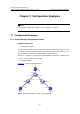
2.1.3 DR Configuration Example
I. Network requirements
1) Requirement analysis
Use OSPF to realize interconnection between devices in a broadcast network. Devices
with higher performance should become the DR and BDR to improve network
performance. Devices with lower performance are forbidden to take part in DB/BDR
election.
Based on the customer requirements and networking environment, assign proper
priorities to interfaces.
2) Network diagram
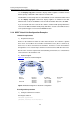
Figure 2-3 shows the network diagram.
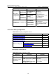
Device Interface IP address Router ID Interface priority
Switch A Vlan-int1 196.1.1.1/24 1.1.1.1 100
Switch B Vlan-int1 196.1.1.2/24 2.2.2.2 0
Switch C Vlan-int1 196.1.1.3/24 3.3.3.3 2
Switch D Vlan-int1 196.1.1.4/24 4.4.4.4 1
Figure 2-3 Network diagram for OSPF DR selection
II. Configuration procedure
# Configure Switch A.
<SwitchA> system-view
[SwitchA] interface Vlan-interface 1
[SwitchA-Vlan-interface1] ip address 196.1.1.1 255.255.255.0
[SwitchA-Vlan-interface1] ospf dr-priority 100
[SwitchA-Vlan-interface1] quit
[SwitchA] router id 1.1.1.1
[SwitchA] ospf
[SwitchA-ospf-1] area 0
[SwitchA-ospf-1-area-0.0.0.0] network 196.1.1.0 0.0.0.255