
H3C S7500 Series Ethernet Switches Release 3135 DHCP Configuration Examples


Routing Configuration Examples
H3C S7500 Series Ethernet Switches Release 3135 Chapter 2 Configuration Examples
2-6
Use the display ospf peer command to display OSPF neighbors on Switch A. Note
that the priority of Switch B is 200 now, but it is not the DR.
The DR will be reelected only after the current DR fails to work. Shut down Switch A and
use the display ospf peer command to display neighbors on Switch D. Note that
Switch C that used to be the BDR becomes the DR and Switch B becomes the BDR.
If you shut down and then restart all the switches, Switch B with priority 200 will be
elected as the DR and Switch A with priority 100 will be elected as the BDR, because
such operation triggers a new round of DR/BDR election.
2.1.4 OSPF Virtual Link Configuration Examples
I. Network requirements
1) Requirement analysis
Devices in the network run OSPF to realize interconnection. The network is split into
three areas: one backbone area and two non-backbone areas (Area 1 and Area 2).
Area 2 has no direct connection to the backbone, and it has to reach the backbone
through Area 1. The customer hopes that Area 2 can interconnect with other two areas.
Based on the customer requirements and networking environment, use a virtual link to
connect Area 2 to the backbone area.
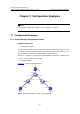
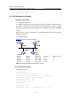
2) Network diagram
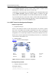
Figure 2-4 shows the network diagram.
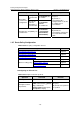
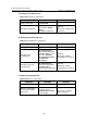
Device Interface IP address Router ID
Switch A Vlan-int1 196.1.1.2/24 1.1.1.1
Vlan-int2 197.1.1.2/24 —
Switch B Vlan-int1 152.1.1.1/24 2.2.2.2
Vlan-int2 197.1.1.1/24 —
Figure 2-4 Network diagram for virtual link configuration
II. Configuration procedure
1) Configure OSPF basic functions
# Configure Switch A.
<SwitchA> system-view
[SwitchA] interface vlan-interface 1