
H3C S7500 Series Ethernet Switches Release 3135 DHCP Configuration Examples


Routing Configuration Examples
H3C S7500 Series Ethernet Switches Release 3135 Chapter 2 Configuration Examples
2-14
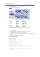
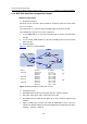
Device Interface IP address AS
Switch A Vlan-int 100 1.1.1.1/8
Vlan-int 2 192.1.1.1/24
100
Switch B Vlan-int 2 192.1.1.2/24
Vlan-int 3 193.1.1.2/24
Switch C Vlan-int 3 193.1.1.1/24
Vlan-int 4 194.1.1.1/24
Switch D Vlan-int 4 194.1.1.2/24
200
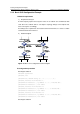
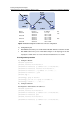
Figure 2-7 Network diagram for BGP route reflector configuration
3) Configuration plan
z Run EBGP between the peers in AS 100 and AS 200. Advertise network 1.0.0.0/8.
z Run IBGP between the peers in AS 200. Configure a star topology for the AS.
Specify the central device as a route reflector and other devices as clients.
II. Configuration procedure
1) Configure switch A.
<SwitchA> system-view
[SwitchA] interface Vlan-interface 2
[SwitchA-Vlan-interface2] ip address 192.1.1.1 255.255.255.0
[SwitchA-Vlan-interface2] interface Vlan-interface 100
[SwitchA-Vlan-interface100] ip address 1.1.1.1 255.0.0.0
[SwitchA-Vlan-interface100] quit
[SwitchA] bgp 100
[SwitchA-bgp] group ex external
[SwitchA-bgp] peer 192.1.1.2 group ex as-number 200
[SwitchA-bgp] network 1.0.0.0 255.0.0.0
2) Configure Switch B.
# Configure the VLAN interface IP addresses.
<SwitchB> system-view
[SwitchB] interface Vlan-interface 2
[SwitchB-Vlan-interface2] ip address 192.1.1.2 255.255.255.0
[SwitchB-Vlan-interface2] quit
[SwitchB] interface Vlan-interface 3
[SwitchB-Vlan-interface3] ip address 193.1.1.2 255.255.255.0