
H3C S7500 Series Ethernet Switches Release 3135 DHCP Configuration Examples


DHCP Configuration Examples
H3C S7500 Series Ethernet Switches Release 3135 Chapter 2 Configuration Examples
2-5
and the DHCP relay agent are interconnected through the 172.16.2.4/30 network
segment.
z Configure the address check function on the DHCP relay agent so that only the
devices that are assigned legal IP addresses from the DHCP server are allowed to
access the external network.
z Enable Option 82 support on the DHCP snooping device (S7502), adding local
port information to the Option 82 field in DHCP messages.
z Enable the DHCP relay agent to support DHCP Option 82 so that the DHCP relay
agent keeps the original filed unchanged upon receiving DHCP messages
carrying Option 82.
z Enable the DHCP server to support DHCP Option 82 so that it assigns
192.168.10.2 through 192.168.10.25 to the DHCP clients connected to Ethernet
2/0/12 of the DHCP snooping device, and assigns 192.168.10.100 through
192.168.10.110 to the DHCP clients connected to Ethernet 2/0/13 of the DHCP
snooping device.
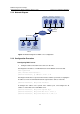
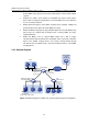
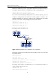
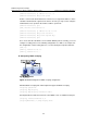
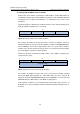
2.2.2 Network Diagram
IP network
VLAN-int 10
192.168.10.1
Eth2/0/1
Eth2/0/11
Eth2/0/12
Eth2/0/13
VLAN-int 17
172.16.2.4/30
VLAN-int 15
192.168.17.1
0010-5ce9-1dea
VLAN-int 25
192.168.19.1
Lab2
HQ
Office Lab1
Lab
DHCP Server
DHCP Snooping
000F-E234-BC66
Cisco Catalyst
3745
192.168.0.3
DHCP Relay
Office server
192.168.10.3
00-14-22-2c-aa-69
Figure 2-2 Network diagram for DHCP relay agent/snooping integrated configuration