
H3C S7500 Series Ethernet Switches Release 3135 DHCP Configuration Examples

Routing Configuration Examples
H3C S7500 Series Ethernet Switches Release 3135 Chapter 3 Comprehensive Configuration Example
3-9
[S400_0-ospf-1-area-0.0.1.44] network 166.1.4.0 0.0.0.255
III. Basic BGP configuration
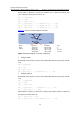
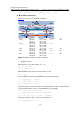
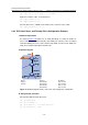
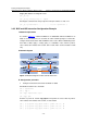
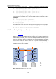
Figure 3-5 shows the relevant network diagram.
Device Interface IP address Router ID AS
S100_1 Vlan-int 11 196.1.1.1/24 1.1.1.1
Vlan-int 15 196.1.3.1/24
Vlan-int 31 196.3.1.1/24
S100_2 Vlan-int 22 196.2.2.1/24 1.2.1.1
Vlan-int 23 196.2.3.2/24
Vlan-int 31 196.3.1.2/24
100
S200 Vlan-int 11 196.1.1.3/24 2.1.1.1
Vlan-int 13 206.1.3.3/24
200
S300 Vlan-int 22 196.2.2.2/24 3.1.1.1
Vlan-int 13 206.1.3.2/24
300
S400 Vlan-int 15 196.1.3.3/24 4.1.1.1
Vlan-int 23 196.2.3.3/24
400
Figure 3-5 Network diagram for BGP configuration
z Configure S100_1.
# Configure the router ID of S100_1 as 1.1.1.1.
<S100_1> system-view
[S100_1] router id 1.1.1.1
# Enable BGP and specify the local AS number as 100.
[S100_1] bgp 100
# Create IBGP peer group 100 and EBGP peer groups 200 and 400.
[S100_1-bgp] group 100 internal
[S100_1-bgp] group 200 external
[S100_1-bgp] group 400 external
# Add peer 196.3.1.2 in AS 100 into peer group 100; Add peer 196.1.1.3 in AS 200 into
peer group 200; Add peer 196.1.3.3 in AS 400 into peer group 400.
[S100_1-bgp] peer 196.3.1.2 group 100
[S100_1-bgp] peer 196.1.1.3 group 200 as-number 200
[S100_1-bgp] peer 196.1.3.3 group 400 as-number 400
# Advertise networks 196.1.3.0, 196.3.1.0, and 196.1.1.0.
[S100_1-bgp] network 196.1.3.0