
H3C S7500 Series Ethernet Switches Release 3135 DHCP Configuration Examples

Multicast Protocol Configuration Examples
H3C S7500 Series Ethernet Switches Release 3135
Chapter 2 Multicast Protocol
Configuration Examples
2-1
Chapter 2 Multicast Protocol Configuration
Examples
2.1 PIM-DM plus IGMP plus IGMP Snooping Configuration
Example
2.1.1 Requirement Analysis
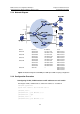
When users receive voice on demand (VOD) information through multicast, the
information receiving mode may vary based on user requirements:
1) To avoid video broadcast at Layer 2, IGMP Snooping is enabled on Switch E,
through which Host A and Host B receive the multicast data.
2) To ensure reliable and stable reception of multicast data, Switch B and Switch C
provide uplink backup for the directly attached stub network N1, which comprises
multicast receivers Host C and Host D.
3) All the Layer 3 switches run RIP for unicast routing and run PIM-DM for multicast
routing.
2.1.2 Configuration Plan
1) Switch D connects to the network that comprises the multicast source (Source)
through VLAN-interface 300.
2) Switch A connects to Switch E through VLAN-interface 100, and to Switch D
through VLAN-interface 103.
3) Switch B and Switch C connect to stub network N1 through their respective
VLAN-interface 200, and to Switch D through VLAN-interface 101 and
VLAN-interface 102 respectively.
4) Enable IGMPv2 on VLAN-interface 100 of Switch A. Enable IGMP Snooping on
Switch E and in VLAN 100. Run IGMPv2 on Switch B, Switch C, and the hosts in
stub network N1. Typically, Switch B acts as the IGMP querier.