
H3C S7500 Series Ethernet Switches Release 3135 DHCP Configuration Examples

Multicast Protocol Configuration Examples
H3C S7500 Series Ethernet Switches Release 3135
Chapter 2 Multicast Protocol
Configuration Examples
2-2
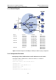
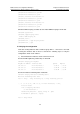
2.1.3 Network Diagram
Ethernet
Ethernet
N1
Vlan-
int1
02
Vl
an
-
int102
Vl
an
-
i
nt1
03
Vlan-in
t
103
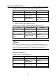
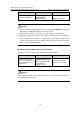
Device Interface IP address Ports
Switch A Vlan-int100 10.110.1.1/24 Ethernet1/0/1
Vlan-int103 192.168.1.1/24 Ethernet1/0/2
Switch B Vlan-int200 10.110.2.1/24 Ethernet1/0/1
Vlan-int101 192.168.2.1/24 Ethernet1/0/2
Switch C Vlan-int200 10.110.2.2/24 Ethernet1/0/1
Vlan-int102 192.168.3.1/24 Ethernet1/0/2
Switch D Vlan-int300 10.110.5.1/24 Ethernet1/0/1
Vlan-int103 192.168.1.2/24 Ethernet1/0/2
Vlan-int101 192.168.2.2/24 Ethernet1/0/3
Vlan-int102 192.168.3.2/24 Ethernet1/0/4
Switch E Vlan 100 — Ethernet1/0/1,
Ethernet1/0/2,
Ethernet1/0/3
Figure 2-1 Network diagram for PIM-DM plus IGMP plus IGMP Snooping configuration
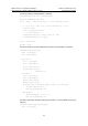
2.1.4 Configuration Procedure
I. Configuring VLANs, VLAN interfaces and IP addresses on each switch
# Configure VLANs, VLAN interfaces, and their IP addresses on Switch A.
<SwitchA> system-view
System View: return to User View with Ctrl+Z.
[SwitchA] vlan 100
[SwitchA-vlan100] port Ethernet 1/0/1
[SwitchA-vlan100] quit
[SwitchA] vlan 103
[SwitchA-vlan103] port Ethernet 1/0/2