
H3C S7500 Series Ethernet Switches Release 3135 DHCP Configuration Examples


Multicast Protocol Configuration Examples
H3C S7500 Series Ethernet Switches Release 3135
Chapter 2 Multicast Protocol
Configuration Examples
2-8
Matched 5 pkts(7500 bytes), Wrong If 0 pkts
Forwarded 0 pkts(0 bytes)
Total 1 entry Listed
# View multicast group information on Switch A.
<SwitchA> display igmp group
Total 0 IGMP groups reported on this router
After multicast group filtering is enabled, the corresponding port cannot receive IGMP
reports. Thus, the corresponding multicast groups are deleted after the port aging timer
expires.
Note:
As shown above, IGMP Snooping multicast group filtering has the same function as
IGMP multicast group filtering. You can use either approach based on the specific
situation.
2.2 PIM-SM plus IGMP plus IGMP Snooping Configuration
Examples
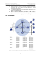
2.2.1 Requirement Analysis
When users receive VOD information through multicast, the information receiving
mode may vary based on user requirements:
1) To avoid broadcasting of the video information at Layer 2, IGMP Snooping is
enabled on Switch E, through which Host A and Host B receive the multicast data.
2) To ensure reliable and stable reception of multicast data, Switch B and Switch C
provide uplink backup for the directly attached stub network N1, which comprises
multicast receivers Host C and Host D.
3) Configure the PIM-SM domain as a single-BSR domain. Run OSPF for unicast
routing in the domain.
2.2.2 Configuration Plan
1) Switch D connects to the network that comprises the multicast source (Source)
through VLAN-interface 300.
2) Switch A connects to Switch F through VLAN-interface 100, and to Switch D and
Switch E through VLAN-interface 101 and VLAN-interface 102 respectively.