
H3C S7500 Series Ethernet Switches Release 3135 DHCP Configuration Examples


Multicast Protocol Configuration Examples
H3C S7500 Series Ethernet Switches Release 3135
Chapter 2 Multicast Protocol
Configuration Examples
2-10
2.2.4 Configuration Procedure
I. Configuring VLANs, VLAN interfaces and IP addresses for each switch
# Configure VLANs, VLAN interfaces, and their IP addresses on Switch A.
<SwitchA> system-view
System View: return to User View with Ctrl+Z.
[SwitchA] vlan 100
[SwitchA-vlan100] port Ethernet 1/0/1
[SwitchA-vlan100] quit
[SwitchA] vlan 101
[SwitchA-vlan101] port Ethernet 1/0/2
[SwitchA-vlan101] quit
[SwitchA] vlan 102
[SwitchA-vlan102] port Ethernet 1/0/3
[SwitchA-vlan102] quit
[SwitchA] interface Vlan-interface 100
[SwitchA-Vlan-interface100] ip address 10.110.1.1 24
[SwitchA-Vlan-interface100] quit
[SwitchA] interface Vlan-interface 101
[SwitchA-Vlan-interface101] ip address 192.168.1.1 24
[SwitchA-Vlan-interface101] quit
[SwitchA] interface Vlan-interface 102
[SwitchA-Vlan-interface102] ip address 192.168.9.1 24
[SwitchA-Vlan-interface102] quit
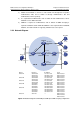
Configure VLANs, VLAN interfaces, and their IP addresses on other switches as per
Figure 2-2. The detailed configuration steps are omitted here.
II. Configuring the unicast routing protocol
# Configure a router ID and enable OSPF on Switch A.
<SwitchA> system-view.
[SwitchA]router id 1.1.1.1
[SwitchA]ospf
[SwitchA-ospf-1]area 0
[SwitchA-ospf-1-area-0.0.0.0]network 10.110.1.0 0.0.0.255
[SwitchA-ospf-1-area-0.0.0.0]network 192.168.1.0 0.0.0.255
[SwitchA-ospf-1-area-0.0.0.0]network 192.168.9.0 0.0.0.255
The configuration on Switch B, Switch C, Switch D, and Switch E is similar to the
configuration on Switch A.