
H3C S7500 Series Ethernet Switches Release 3135 DHCP Configuration Examples

QACL Configuration Examples
H3C S7500 Series Ethernet Switches Release 3135 Chapter 2 QACL Configuration Examples
2-10
2.2 Configuration Example in a Service Provider Network
VLAN 10
GE2/0/1
GE2/0/2
VLAN 20
1234-5678-9000 to
1234-5678-90FF
Switch A
Service provider
network
VLAN100/VLAN200
VLAN 10
VLAN 20
Client-side
network
Switch B
GE2/0/2
GE2/0/1
VLAN 20
GE2/0/2
GE2/0/1
VLAN 100
VLAN 200
Switch C
Server-side
network
Server-side
network
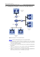
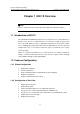
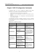
Figure 2-6 Topology of a service provider network
Figure 2-6 shows the network topology of the service provider network:
z The S7500 switches (Switch A, Switch B, and Switch C in the network diagram)
operate as the edge devices of the service provider network and are connected to
server-side or client-side networks.
z The service provider network permits the packets of VLAN 100 and VLAN 200 to
pass through.
z Switch B is connected to the service provider network through GigabitEthernet
2/0/2, which permits the packets of VLAN 100 to pass through.
z Switch C is connected to the service provider network through GigabitEthernet
2/0/2, which permits the packets of VLAN 200 to pass through.