H3C S7500E Series Ethernet Switches Command Manual Hangzhou H3C Technologies Co., Ltd. http://www.h3c.com Manual Version: 20071025-C-1.
Copyright © 2007, Hangzhou H3C Technologies Co., Ltd. and its licensors All Rights Reserved No part of this manual may be reproduced or transmitted in any form or by any means without prior written consent of Hangzhou H3C Technologies Co., Ltd. Trademarks H3C, , Aolynk, , H3Care, , TOP G, , IRF, NetPilot, Neocean, NeoVTL, SecPro, SecPoint, SecEngine, SecPath, Comware, Secware, Storware, NQA, VVG, V2G, VnG, PSPT, XGbus, N-Bus, TiGem, InnoVision and HUASAN are trademarks of Hangzhou H3C Technologies Co.
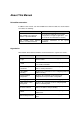
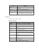
About This Manual Related Documentation In addition to this manual, each H3C S7500E Series Ethernet Switches documentation set includes the following: Manual Description H3C S7500E Series Ethernet Switches Operation Manual It is used for assisting the users in data configurations and typical applications. (See the electronic documentation for details) H3C S7500E Series Ethernet Switches Installation Manual It provides information for the system installation.
Part Contents 11 IPv4 Routing Introduces the commands used for configuring IPv4 routing, static routing, RIP, OSPF, IS-IS, BGP, and route policy. 12 IPv6 Routing Introduces the commands used for configuring IPv6 routing, static routing, RIPng, OSPFv3, IS-ISv6, and BGP4+. 13 IPv6 Configuration Introduces the commands used for configuring IPv6 application, IPv6 tunneling, and so on.
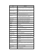
Part Contents 30 SSH Introduces the commands used for SSH and the related configuration. 31 PoE Introduces the commands used for PoE. 32 RRPP Introduces the commands used for RRPP. 33 Appendix Lists all the commands described in this command manual in an alphabetic order. The parts and pages where the commands are described are also given. Conventions The manual uses the following conventions: I.
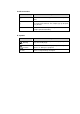
II. GUI conventions Convention Description <> Button names are inside angle brackets. For example, click . [] Window names, menu items, data table and field names are inside square brackets. For example, pop up the [New User] window. / Multi-level menus are separated by forward slashes. For example, [File/Create/Folder]. III. Symbols Convention Description Warning Means reader be extremely careful. Improper operation may cause bodily injury. Caution Means reader be careful.
Command Manual – Login H3C S7500E Series Ethernet Switches Table of Contents Table of Contents Chapter 1 Commands for Logging into an Ethernet Switch ..................................................... 1-1 1.1 Commands for Logging into an Ethernet Switch ............................................................... 1-1 1.1.1 activation-key .......................................................................................................... 1-1 1.1.2 authentication-mode............................
Command Manual – Login H3C S7500E Series Ethernet Switches Table of Contents 2.1.1 acl............................................................................................................................ 2-1 2.1.2 snmp-agent community........................................................................................... 2-2 2.1.3 snmp-agent group ................................................................................................... 2-2 2.1.4 snmp-agent usm-user ....................
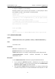
Command Manual – Login H3C S7500E Series Ethernet Switches Chapter 1 Commands for Logging into an Ethernet Switch Chapter 1 Commands for Logging into an Ethernet Switch 1.1 Commands for Logging into an Ethernet Switch 1.1.1 activation-key Syntax activation-key character undo activation-key View AUX interface view Parameters character: Shortcut key for starting terminal sessions, a character or its ASCII decimal equivalent in the range 0 to 127; or a string of 1 to 3 characters.
Command Manual – Login H3C S7500E Series Ethernet Switches Chapter 1 Commands for Logging into an Ethernet Switch To verify the configuration, do the following: # Exit the terminal session on the aux port, and enter at the prompt of “Please press ENTER”. You will see the terminal session being started. [Sysname-ui-aux0] return quit ************************************************************************** * Copyright (c) 2004-2007 Hangzhou H3C Tech. Co., Ltd. All rights reserved.
Command Manual – Login H3C S7500E Series Ethernet Switches Chapter 1 Commands for Logging into an Ethernet Switch related configuration. Refer to the AAA-RADIUS-HWTACACS module of this manual for more. z If this command is executed with the command-authorization keywords specified, authorization is performed on the TACACS server whenever you attempt to execute a command, and the command can be executed only when you pass the authorization.
Command Manual – Login H3C S7500E Series Ethernet Switches Chapter 1 Commands for Logging into an Ethernet Switch Description Use the auto-execute command command to set the command that is executed automatically after a user logs in. Use the undo auto-execute command command to disable the specified command from being automatically executed. Use these two commands in the VTY user interface only.
Command Manual – Login H3C S7500E Series Ethernet Switches Chapter 1 Commands for Logging into an Ethernet Switch View AUX interface view Parameters 5: Five data bits. 6: Six data bits. 7: Seven data bits. 8: Eight data bits. Description Use the databits command to set the databits for the user interface. Use the undo databits command to revert to the default data bits. The default data bits is 8. Note: H3C S7500E Series Ethernet Switches only support data bits 7 and 8.
Command Manual – Login H3C S7500E Series Ethernet Switches Chapter 1 Commands for Logging into an Ethernet Switch Description Use the display telnet client configuration command to display the source IP address or source interface configured for the current device. Example # Display the source IP address or source interface configured for the current device. display telnet client configuration The source IP address is 1.1.1.1. 1.1.
Command Manual – Login H3C S7500E Series Ethernet Switches Chapter 1 Commands for Logging into an Ethernet Switch F : Current user-interface is active and work in async mode. Idx : Absolute index of user-interface. Type : Type and relative index of user-interface. Privi: The privilege of user-interface. Auth : The authentication mode of user-interface. Int A : The physical location of UIs. : Authenticate use AAA. L : Authentication use local database. N : Current UI need not authentication.
Command Manual – Login H3C S7500E Series Ethernet Switches Chapter 1 Commands for Logging into an Ethernet Switch Examples # Display the information about the current user interface. display users The user application information of the user interface(s): Idx UI Delay Type Userlevel 1 VTY 0 00:11:45 TEL 3 2 VTY 1 00:16:35 TEL 3 3 VTY 2 00:16:54 TEL 3 + 4 VTY 3 00:00:00 TEL 3 Following are more details. VTY 0 : Location: 192.168.0.123 VTY 1 : Location: 192.168.0.
Command Manual – Login H3C S7500E Series Ethernet Switches Chapter 1 Commands for Logging into an Ethernet Switch 1.1.8 escape-key Syntax escape-key { default | character } undo escape-key View User interface view Parameters default: Restores the default escape key combination . character: Specifies the shortcut key for aborting a task, a single character (or its corresponding ASCII code value in the range 0 to 127) or a string of 1 to 3 characters.
Command Manual – Login H3C S7500E Series Ethernet Switches Chapter 1 Commands for Logging into an Ethernet Switch 100.00% packet loss Enter , if the ping task is terminated and return to the current view, the configuration is correct. 1.1.9 flow-control Syntax flow-control { hardware | none | software } undo flow-control View AUX interface view Parameters hardware: Configures to perform hardware flow control. none: Configures no flow control.
Command Manual – Login H3C S7500E Series Ethernet Switches Chapter 1 Commands for Logging into an Ethernet Switch 1.1.10 free user-interface Syntax free user-interface [ type ] number View User view Parameters type: User interface type. number: Absolute user interface index or relative user interface index. z Relative user interface index: If you provide the type argument, number indicates the user interface index of the type.
Command Manual – Login H3C S7500E Series Ethernet Switches Chapter 1 Commands for Logging into an Ethernet Switch Parameters value: Size of the history command buffer. This argument ranges from 0 to 256 and defaults to 10. That is, the history command buffer can store 10 commands by default. Description Use the history-command max-size command to set the size of the history command buffer. Use the undo history-command max-size command to revert to the default history command buffer size.
Command Manual – Login H3C S7500E Series Ethernet Switches Chapter 1 Commands for Logging into an Ethernet Switch Examples # Set the timeout time of AUX 0 to 1 minute. system-view System View: return to User View with Ctrl+Z. [Sysname] user-interface aux 0 [Sysname-ui-aux0] idle-timeout 1 0 1.1.13 lock Syntax lock View User view Parameters None Description Use the lock command to lock the current user interface to prevent unauthorized users from operating the user interface.
Command Manual – Login H3C S7500E Series Ethernet Switches Chapter 1 Commands for Logging into an Ethernet Switch 1.1.14 modem Syntax modem [ both | call-in | call-out ] undo modem [ both | call-in | call-out ] View AUX interface view Parameters both: Allows both incoming and outgoing calls. call-in: Allows incoming calls only. call-out: Allows outgoing calls only. Description Use the modem command to enable the switch-side modem to accept incoming calls, initiate outgoing calls, or both.
Command Manual – Login H3C S7500E Series Ethernet Switches Chapter 1 Commands for Logging into an Ethernet Switch Description Use the modem auto-answer command to configure the switch-side modem to operate in the auto-answer mode. Use the undo modem auto-answer command to restore the default. By default, the switch-side modem operates in the manual answer mode. Examples # Configure the switch-side modem to operate in the auto-answer mode.
Command Manual – Login H3C S7500E Series Ethernet Switches Chapter 1 Commands for Logging into an Ethernet Switch 1.1.17 parity Syntax parity { even | mark | none | odd | space } undo parity View AUX interface view Parameters even: Performs even checks. mark: Performs mark checks. none: Does not check. odd: Performs odd checks. space: Performs space checks. Description Use the parity command to set the check mode of the user interface. Use the undo parity command to revert to the default check mode.
Command Manual – Login H3C S7500E Series Ethernet Switches Chapter 1 Commands for Logging into an Ethernet Switch View VTY interface view Parameters all: Supports both Telnet protocol and SSH protocol. ssh: Supports SSH protocol. telnet: Supports Telnet protocol. Description Use the protocol inbound command to configure the user interface to support specified protocols. Both Telnet and SSH protocols are supported by default. Related command: user-interface vty.
Command Manual – Login H3C S7500E Series Ethernet Switches Chapter 1 Commands for Logging into an Ethernet Switch Parameters screen-length: Number of lines the screen can contain. This argument ranges from 0 to 512 and defaults to 24. Description Use the screen-length command to set the number of lines the terminal screen can contain. Use the undo screen-length command to revert to the default number of lines.
Command Manual – Login H3C S7500E Series Ethernet Switches Chapter 1 Commands for Logging into an Ethernet Switch Examples # Send messages to all user interfaces. send all Enter message, end with CTRL+Z or Enter; abort with CTRL+C: hello^Z Send message? [Y/N]y *** *** ***Message from vty0 to vty0 *** hello 1.1.
Command Manual – Login H3C S7500E Series Ethernet Switches Chapter 1 Commands for Logging into an Ethernet Switch Commands fall into four command levels: visit, monitor, system, and manage, which are described as follows: z Visit level: Commands of this level are used to diagnose network and change the language mode of user interface, such as the ping, tracert. The Telnet command is also of this level. Commands of this level cannot be saved in configuration files.
Command Manual – Login H3C S7500E Series Ethernet Switches Chapter 1 Commands for Logging into an Ethernet Switch undo set authentication password View User interface view Parameters cipher: Specifies to display the local password in encrypted text when you display the current configuration. simple: Specifies to display the local password in plain text when you display the current configuration. password: Password.
Command Manual – Login H3C S7500E Series Ethernet Switches Chapter 1 Commands for Logging into an Ethernet Switch 1.1.23 shell Syntax shell undo shell View User interface view Parameters None Description Use the shell command to make terminal services available for the user interface. Use the undo shell command to make terminal services unavailable to the user interface. By default, terminal services are available in all user interfaces.
Command Manual – Login H3C S7500E Series Ethernet Switches Chapter 1 Commands for Logging into an Ethernet Switch View AUX interface view Parameters speed-value: Transmission speed (in bps). This argument can be 300, 600, 1200, 2400, 4800, 9600, 19,200, 38,400, 57,600, 115,200 and defaults to 9,600. Description Use the speed command to set the transmission speed of the user interface. Use the undo speed command to revert to the default transmission speed.
Command Manual – Login H3C S7500E Series Ethernet Switches Chapter 1 Commands for Logging into an Ethernet Switch Description Use the stopbits command to set the stop bits of the user interface. Use the undo stopbits command to revert to the default stop bits. By default, the stop bits is 1. Note: The stopbits cannot be 1.5 on an S7500E series Ethernet switch. Examples # Set the stop bits to 2. system-view System View: return to User View with Ctrl+Z.
Command Manual – Login H3C S7500E Series Ethernet Switches Chapter 1 Commands for Logging into an Ethernet Switch System View: return to User View with Ctrl+Z. [Sysname] sysname ABC [ABC] 1.1.27 telnet Syntax telnet remote-system [ port-number ] [ source { ip ip-address | interface interface-type interface-number } ] View User view Parameters remote-system: IP address or host name of the remote system. The host name is a string of 1 to 20 characters, which can be specified using the ip host command.
Command Manual – Login H3C S7500E Series Ethernet Switches Chapter 1 Commands for Logging into an Ethernet Switch 1.1.28 telnet ipv6 Syntax telnet ipv6 remote-system [ -i interface-type interface-number ] [ port-number ] View User view Parameters remote-system: IPv6 address or host name of the remote system. An IPv6 address can be up to 46 characters; a host name is a string of 1 to 20 characters.
Command Manual – Login H3C S7500E Series Ethernet Switches Chapter 1 Commands for Logging into an Ethernet Switch View System view Parameters None Description Use the telnet client source command to specify the source IP address or source interface for the Telnet packets to be sent. Use the undo telnet client source command to remove the source IP address or source interface configured for Telnet packets. By default, source IP address or source interface of the Telnet packets sent is not configured.
Command Manual – Login H3C S7500E Series Ethernet Switches Chapter 1 Commands for Logging into an Ethernet Switch Examples # Make the switch to operate as a Telnet Server. system-view [Sysname] telnet server enable % Start Telnet server # Disable the switch from operating as a Telnet server. [Sysname] undo telnet server enable % Close Telnet server 1.1.
Command Manual – Login H3C S7500E Series Ethernet Switches Chapter 1 Commands for Logging into an Ethernet Switch 1.1.32 user-interface Syntax user-interface [ type ] first-number [ last-number ] View System view Parameters type: User interface type. first-number: User interface index, which identifies the first user interface to be configured. last-number: User interface index, which identifies the last user interface to be configured.
Command Manual – Login H3C S7500E Series Ethernet Switches Chapter 1 Commands for Logging into an Ethernet Switch Use the undo user privilege level command to revert to the default command level. By default, the commands of level 3 are available to the users logging into the AUX user interface. The commands of level 0 are available to the users logging into VTY user interfaces. Examples # Configure that commands of level 0 are available to the users logging into VTY 0.
Command Manual – Login H3C S7500E Series Ethernet Switches Chapter 2 Commands for Controlling Login Users Chapter 2 Commands for Controlling Login Users 2.1 Commands for Controlling Login Users 2.1.
Command Manual – Login H3C S7500E Series Ethernet Switches Chapter 2 Commands for Controlling Login Users 2.1.2 snmp-agent community Syntax snmp-agent community { read | write } community-name [ mib-view view-name | acl acl-number ]* undo snmp-agent community community-name View System view Parameters read: Specifies that the community has read-only permission in the specified view. write: Specifies that the community has read/write permission in the specified view.
Command Manual – Login H3C S7500E Series Ethernet Switches Chapter 2 Commands for Controlling Login Users undo snmp-agent group { v1 | v2c } group-name snmp-agent group v3 group-name [ authentication | privacy ] [ read-view read-view ] [ write-view write-view ] [ notify-view notify-view ] [ acl acl-number ] undo snmp-agent group v3 group-name [ authentication | privacy ] View System view Parameters v1: Specifies to adopt v1 security scheme. v2c: Specifies to adopt v2c security scheme.
Command Manual – Login H3C S7500E Series Ethernet Switches Chapter 2 Commands for Controlling Login Users 2.1.
Command Manual – Login H3C S7500E Series Ethernet Switches Chapter 2 Commands for Controlling Login Users Description Use the snmp-agent usm-user command to add a user to a specified SNMP group. You can also optionally use this command to apply an ACL to filter network management users. Use the undo snmp-agent usm-user command to remove a user from the corresponding SNMP group. The operation also frees the user from the corresponding ACL-related configuration.
Command Manual – VLAN H3C S7500E Series Ethernet Switches Table of Contents Table of Contents Chapter 1 VLAN Configuration Commands................................................................................ 1-1 1.1 VLAN Configuration Commands........................................................................................ 1-1 1.1.1 description ............................................................................................................... 1-1 1.1.
Command Manual – VLAN H3C S7500E Series Ethernet Switches Table of Contents 3.1.4 voice vlan aging....................................................................................................... 3-4 3.1.5 voice vlan enable .................................................................................................... 3-4 3.1.6 voice vlan mac-address .......................................................................................... 3-5 3.1.7 voice vlan mode auto ........................
Command Manual – VLAN H3C S7500E Series Ethernet Switches Chapter 1 VLAN Configuration Commands Chapter 1 VLAN Configuration Commands 1.1 VLAN Configuration Commands 1.1.1 description Syntax description text undo description View VLAN view/VLAN interface view Parameters text: String that describes the current VLAN or VLAN interface (Space can be included), case sensitive. z For VLAN, this is a string of 1 to 32 characters. z For VLAN interface, this is a string of 1 to 80 characters.
Command Manual – VLAN H3C S7500E Series Ethernet Switches Chapter 1 VLAN Configuration Commands 1.1.2 display interface Vlan-interface Syntax display interface Vlan-interface [ vlan-interface-id ] View Any view Parameters vlan-interface-id: VLAN interface ID. Description Use the display interface Vlan-interface command to display the relevant information of a VLAN interface.
Command Manual – VLAN H3C S7500E Series Ethernet Switches Chapter 1 VLAN Configuration Commands Field Description Hardware address MAC address corresponding to a VLAN interface IPv6 Packet Frame Type IPv6 outgoing frame format 1.1.3 display vlan Syntax display vlan [ vlan-id1 [ to vlan-id2 ] | all | dynamic | reserved | static ] View Any view Parameters vlan-id1: Displays the information of a VLAN specified by VLAN ID in the range of 1 to 4,094.
Command Manual – VLAN H3C S7500E Series Ethernet Switches Chapter 1 VLAN Configuration Commands # Display VLAN 3 information. display vlan 3 VLAN ID: 3 VLAN Type: static Route Interface: configured IP Address: 1.1.1.1 Subnet Mask: 255.255.255.
Command Manual – VLAN H3C S7500E Series Ethernet Switches Chapter 1 VLAN Configuration Commands Description Use the interface Vlan-interface command to enter the specified VLAN interface view. Use the undo interface Vlan-interface command to delete the specified VLAN interface. The VLAN interface must be created first before entering its view Before creating a VLAN interface, make sure the corresponding VLAN has been created; otherwise, the VLAN interface cannot be created.
Command Manual – VLAN H3C S7500E Series Ethernet Switches Chapter 1 VLAN Configuration Commands Normally, a VLAN interface has one IP address. To enable a device to connect to multiple subnets through a VLAN, you can assign multiple IP addresses to a VLAN interface, among which one is the primary IP address and the rest are secondary IP addresses. On an S7500E series Ethernet switch, you can assign up to five IP addresses to a VLAN interface.
Command Manual – VLAN H3C S7500E Series Ethernet Switches Chapter 1 VLAN Configuration Commands You can use the undo shutdown command to bring up a VLAN interface after configurations of the related parameter and protocol. When there is a fault in a VLAN interface, you can use the shutdown command to shut down the interface and then bring it up using the undo shutdown command. In this way, the interface will resume Shutting down/bringing up a VLAN interface does not affect any Ethernet ports in the VLAN.
Command Manual – VLAN H3C S7500E Series Ethernet Switches Chapter 1 VLAN Configuration Commands Note: z As the default VLAN, VLAN 1 cannot be created, or removed. z You cannot create/remove reserved VLANs that are reserved for specific function implementation. z Dynamic VLANs cannot be removed using the undo vlan command. z A VLAN configured with QoS policies cannot be removed.
Command Manual – VLAN H3C S7500E Series Ethernet Switches Chapter 1 VLAN Configuration Commands Description Use the port command to add one Access port or a group of Access ports to a VLAN. Use the undo port command to remove one Access port or a group of Access ports from a VLAN. Note: z This command is only applicable to Access ports. z All ports have their default link type configured as Access, however, users can manually configure the port type. For more information, refer to port link-type.
Command Manual – VLAN H3C S7500E Series Ethernet Switches Chapter 1 VLAN Configuration Commands Examples # Add Ethernet 2/0/1 to VLAN 3. system-view [Sysname] vlan 3 [Sysname-vlan3] quit [Sysname] interface ethernet 2/0/1 [Sysname-Ethernet2/0/1] port access vlan 3 1.2.3 port hybrid pvid vlan Syntax port hybrid pvid vlan vlan-id undo port hybrid pvid View Ethernet port view, port group view Parameters vlan-id : VLAN ID, in the range 1 to 4094.
Command Manual – VLAN H3C S7500E Series Ethernet Switches Chapter 1 VLAN Configuration Commands [Sysname-Ethernet2/0/1] port hybrid pvid vlan 100 1.2.
Command Manual – VLAN H3C S7500E Series Ethernet Switches Chapter 1 VLAN Configuration Commands [Sysname] port-group manual 2 [Sysname-port-group-manual-2] group-member ethernet 2/0/1 to ethernet 2/0/6 [Sysname-port-group-manual-2] port link-type hybrid [Sysname-port-group-manual-2] port hybrid vlan 2 untagged Configuring Ethernet2/0/1... Done. Configuring Ethernet2/0/2... Done. Configuring Ethernet2/0/3... Done. Configuring Ethernet2/0/4... Done. Configuring Ethernet2/0/5... Done.
Command Manual – VLAN H3C S7500E Series Ethernet Switches Chapter 1 VLAN Configuration Commands Examples # Configure Ethernet 2/0/1 to be a Trunk port. system-view [Sysname] interface ethernet 2/0/1 [Sysname-Ethernet2/0/1] port link-type trunk # Configure all the ports in the manual port group group1 as Hybrid ports.
Command Manual – VLAN H3C S7500E Series Ethernet Switches Chapter 1 VLAN Configuration Commands Examples # Add the Trunk port Ethernet 2/0/1 to VLAN 2, VLAN 4, and the range of VLANs from VLAN 50 to VLAN 100. system-view [Sysname] interface ethernet 2/0/1 [Sysname-Ethernet2/0/1] port link-type trunk [Sysname-Ethernet2/0/1] port trunk permit vlan 2 4 50 to 100 Please wait........... Done. 1.2.
Command Manual – VLAN H3C S7500E Series Ethernet Switches Chapter 1 VLAN Configuration Commands [Sysname-Ethernet2/0/1] port trunk pvid vlan 100 1.3 Protocol-Based VLAN Configuration Commands 1.3.1 display protocol-vlan interface Syntax display protocol-vlan interface { interface-type interface-number1 [ to interface-type interface-number2 ] | all } View Any view Parameters interface-type interface-number1: Specifies an port by its type and number.
Command Manual – VLAN H3C S7500E Series Ethernet Switches Chapter 1 VLAN Configuration Commands 1.3.2 display protocol-vlan vlan Syntax display protocol-vlan vlan { vlan-id [ to vlan-id ] | all } View Any view Parameters vlan-id: VLAN ID, in the range 1 to 4094. to: Specifies VLAN range, the value after this parameter must be greater than or equal to that before it. all: All VLANs.
Command Manual – VLAN H3C S7500E Series Ethernet Switches Chapter 1 VLAN Configuration Commands 1.3.3 port hybrid protocol-vlan Syntax port hybrid protocol-vlan vlan vlan-id { protocol-index [ to protocol-end ] | all } undo port hybrid protocol-vlan { vlan vlan-id { protocol-index [ to protocol-end ] | all } | all } View Ethernet port view, port group view Parameters vlan vlan-id: Specifies a VLAN ID, in the range 1 to 4094. protocol-index: Beginning protocol index, in the range 0 to 15.
Command Manual – VLAN H3C S7500E Series Ethernet Switches Chapter 1 VLAN Configuration Commands Examples # Associate the Hybrid port Ethernet 2/0/1, with protocol 0 in VLAN 2. system-view [Sysname] vlan 2 [Sysname-Vlan2] protocol-vlan at [Sysname] interface ethernet 2/0/1 [Sysname-Ethernet2/0/1] port link-type hybrid [Sysname-Ethernet2/0/1] port hybrid vlan 2 untagged Please wait... Done [Sysname-Ethernet2/0/1] port hybrid protocol-vlan vlan 2 0 1.3.
Command Manual – VLAN H3C S7500E Series Ethernet Switches Chapter 1 VLAN Configuration Commands inbound packets, in the range 0x0600 to 0xffff (excluding ipx snap under the snap encapsulation format). protocol-index: Beginning protocol index, in the range 0 to 15. The system will automatically assign an index if this parameter is not specified. to protocol-end: Specifies the end protocol index, which ranges from 0 to 15 and must be greater than or equal to the protocol-index argument.
Command Manual – VLAN H3C S7500E Series Ethernet Switches Chapter 1 VLAN Configuration Commands Caution: Due to the close relationship between IPv4 and ARP, it is recommended to bind the two protocols to the same VLAN and associate the binding to related ports to guarantee normal communication. Configure ARP protocol template for VLAN3 (ARP code is 0x0806) to make the VLAN transmit ARP packets.
Command Manual – VLAN H3C S7500E Series Ethernet Switches VLAN ID Subnet-Index Chapter 1 VLAN Configuration Commands IP ADDRESS NET MASK ======================================================= 3 0 192.168.1.0 255.255.255.
Command Manual – VLAN H3C S7500E Series Ethernet Switches Chapter 1 VLAN Configuration Commands Table 1-5 Description on the fields of the display ip-subnet-vlan vlan command Field Description VLAN ID VLAN ID Subnet Index Subnet Index IP Address IP address of the subnet (can be an IP address or a network address) Subnet Mask Mask of the IP subnet 1.4.
Command Manual – VLAN H3C S7500E Series Ethernet Switches Chapter 1 VLAN Configuration Commands Examples # Configure VLAN 3 to be an IP-subnet-based VLAN. Associate it with the 192.168.1.0/24 network segment. system-view [Sysname] vlan 3 [Sysname-vlan3] ip-subnet-vlan ip 192.168.1.0 255.255.255.0 1.4.
Command Manual – VLAN H3C S7500E Series Ethernet Switches Chapter 1 VLAN Configuration Commands [Sysname] interface ethernet 2/0/1 [Sysname-Ethernet2/0/1] port link-type hybrid [Sysname-Ethernet2/0/1] port hybrid vlan 3 untagged Please wait... Done.
Command Manual – VLAN H3C S7500E Series Ethernet Switches Chapter 2 Isolate-User-VLAN Configuration Commands Chapter 2 Isolate-User-VLAN Configuration Commands 2.1 Isolate-User-VLAN Configuration Commands 2.1.1 display isolate-user-vlan Syntax display isolate-user-vlan [ isolate-user-vlan-id ] View Any view Parameters isolate-user-vlan-id: VLAN ID of an isolate-user-VLAN, in the range 1 to 4094.
Command Manual – VLAN H3C S7500E Series Ethernet Switches Chapter 2 Isolate-User-VLAN Configuration Commands VLAN ID: 3 VLAN Type: static Isolate-user-VLAN type : secondary Route Interface: configured IP Address: 2.2.2.2 Subnet Mask: 255.255.255.
Command Manual – VLAN H3C S7500E Series Ethernet Switches Chapter 2 Isolate-User-VLAN Configuration Commands 2.1.2 isolate-user-vlan Syntax isolate-user-vlan isolate-user-vlan-id secondary secondary-vlan-id-list undo isolate-user-vlan isolate-user-vlan-id [ secondary secondary-vlan-id-list ] View System view Parameters isolate-user-vlan-id: VLAN ID of an isolate-user-vlan, in the range 1 to 4094. secondary secondary-vlan-id-list: Specifies a list of secondary VLAN IDs.
Command Manual – VLAN H3C S7500E Series Ethernet Switches Chapter 2 Isolate-User-VLAN Configuration Commands Note: After the mapping between the isolate-user-vlan and the secondary VLANs is created, no port can be added to or deleted from either the isolate-user-vlan or the secondary VLAN(s). Only after the mapping relation is deleted are the above operations possible. Related commands: display isolate-user-vlan. Examples # Associate the isolate-user-VLAN 2 to the secondary VLANs VLAN 3 and VLAN 4.
Command Manual – VLAN H3C S7500E Series Ethernet Switches Chapter 2 Isolate-User-VLAN Configuration Commands An isolate-user-VLAN may include multiple ports, including those that are connected to upstream devices. Related commands: display isolate-user-vlan. Examples # Configure VLAN 5 to be an isolate-user-VLAN.
Command Manual – VLAN H3C S7500E Series Ethernet Switches Chapter 3 Voice VLAN Configuration Commands Chapter 3 Voice VLAN Configuration Commands 3.1 Voice VLAN Configuration Commands 3.1.1 display voice vlan oui Syntax display voice vlan oui View Any view Parameters None Description Use the display voice vlan oui command to display the organizationally unique identifier (OUI) address(es), the OUI address mask, and the descriptive string currently supported by system.
Command Manual – VLAN H3C S7500E Series Ethernet Switches Chapter 3 Voice VLAN Configuration Commands Table 3-1 Description on the fields of the display voice vlan oui command Field Description Oui Address OUI addresses that are allowed to pass Mask Mask of the OUI addresses that are allowed to pass Description Description of the OUI addresses that are allowed to pass 3.1.
Command Manual – VLAN H3C S7500E Series Ethernet Switches Chapter 3 Voice VLAN Configuration Commands Table 3-2 Description on the fields of the display voice vlan state command Field Description Voice VLAN status The current voice VLAN status, that is, whether it is enabled or disabled.
Command Manual – VLAN H3C S7500E Series Ethernet Switches Chapter 3 Voice VLAN Configuration Commands Examples # Enable the voice VLAN feature on VLAN 2 (assuming that VLAN 2 already exists). system-view [Sysname] voice vlan 2 enable 3.1.4 voice vlan aging Syntax voice vlan aging minutes undo voice vlan aging View System view Parameters minutes: Aging time of a voice VLAN, in the range 5 to 43,200 (in minutes). This value is 1,440 by default.
Command Manual – VLAN H3C S7500E Series Ethernet Switches Chapter 3 Voice VLAN Configuration Commands View Ethernet port view Parameters None Description Use the voice vlan enable command to enable the voice VLAN feature on an Ethernet port. Use the undo voice vlan enable command to disable the voice VLAN feature on an Ethernet port. No voice VLAN is enabled on a port by default. z Under automatic mode, only The Trunk or Hybrid port can be configured with the voice VLAN feature.
Command Manual – VLAN H3C S7500E Series Ethernet Switches Chapter 3 Voice VLAN Configuration Commands description text: Specifies a string that describes the OUI address. The string is of 1 to 30 characters and is case sensitive. oui: Deletes an OUI address that is in the format H-H-H, such as 1234-1200-0000, which is the logic AND result of mac-addr and oui-mask. Using the display voice vlan oui command can display OUI address information.
Command Manual – VLAN H3C S7500E Series Ethernet Switches Chapter 3 Voice VLAN Configuration Commands 0001-e300-0000 ffff-ff00-0000 Siemens phone 0003-6b00-0000 ffff-ff00-0000 Cisco phone 0004-0d00-0000 ffff-ff00-0000 Avaya phone 0060-b900-0000 ffff-ff00-0000 Philips/NEC phone 00d0-1e00-0000 ffff-ff00-0000 Pingtel phone 00e0-7500-0000 ffff-ff00-0000 Polycom phone 00e0-bb00-0000 ffff-ff00-0000 3com phone 1234-1200-0000 ffff-ff00-0000 PhoneA # Disable voice packets of Phone A from pa
Command Manual – VLAN H3C S7500E Series Ethernet Switches Chapter 3 Voice VLAN Configuration Commands 3.1.8 voice vlan security enable Syntax voice vlan security enable undo voice vlan security enable View System view Parameters None Description Use the voice vlan security enable command to enable the security mode for voice VLAN. Use the undo voice vlan security enable command to disable the security mode for voice VLAN. By default, the security mode of voice VLAN is enabled.
Command Manual – VLAN H3C S7500E Series Ethernet Switches Chapter 4 GARP/GVRP Configuration Commands Chapter 4 GARP/GVRP Configuration Commands 4.1 GARP Configuration Commands 4.1.
Command Manual – VLAN H3C S7500E Series Ethernet Switches Chapter 4 GARP/GVRP Configuration Commands 4.1.2 display garp timer Syntax display garp timer [ interface interface-list ] View Any view Parameters interface interface-list: Specifies an Ethernet port list, in the format of { interface-type interface-number [ to interface-type interface-number ] }&<1-10>, where &<1-10> means that you can specify up to 10 port ranges.
Command Manual – VLAN H3C S7500E Series Ethernet Switches Chapter 4 GARP/GVRP Configuration Commands Parameters hold: Sets the hold timer. join: Sets the join timer. leave: Sets the leave timer. timer-value: Timer setting (in centiseconds), which must be a multiple of 5 centiseconds. Description Use the garp timer command to set a GARP timer for an Ethernet port or all ports in a port group in compliance with the timer setting dependencies shown in Table 4-1.
Command Manual – VLAN H3C S7500E Series Ethernet Switches Chapter 4 GARP/GVRP Configuration Commands system-view [Sysname] interface ethernet 2/0/1 [Sysname-Ethernet2/0/1] garp timer join 25 4.1.
Command Manual – VLAN H3C S7500E Series Ethernet Switches Chapter 4 GARP/GVRP Configuration Commands 4.1.5 reset garp statistics Syntax reset garp statistics [ interface interface-list ] View User view Parameters interface interface-list: Specifies an Ethernet port list, in the format of { interface-type interface-number [ to interface-type interface-number ] }&<1-10>, where &<1-10> means that you can specify up to 10 port ranges.
Command Manual – VLAN H3C S7500E Series Ethernet Switches Chapter 4 GARP/GVRP Configuration Commands Description Use the display gvrp local-vlan interface command to display the local VLAN information maintained by GVRP on a port. Examples # Display the local VLAN information maintained by GVRP on Ethernet 2/0/1.
Command Manual – VLAN H3C S7500E Series Ethernet Switches Chapter 4 GARP/GVRP Configuration Commands View Any view Parameters interface interface-list: Specifies an Ethernet port list, in the format of { interface-type interface-number [ to interface-type interface-number ] }&<1-10>, where &<1-10> means that you can specify up to 10 port ranges. A port range defined without the to interface-type interface-number portion comprises only one port.
Command Manual – VLAN H3C S7500E Series Ethernet Switches Chapter 4 GARP/GVRP Configuration Commands 4.2.4 display gvrp status Syntax display gvrp status View Any view Parameters None Description Use the display gvrp status command to display the global enable/disable state of GVRP. Examples # Display the global GVRP enable/disable state. display gvrp status GVRP is enabled 4.2.
Command Manual – VLAN H3C S7500E Series Ethernet Switches Chapter 4 GARP/GVRP Configuration Commands Operations of creating VLAN : 2-100 Operations of deleting VLAN : none Operations of adding VLAN to TRUNK : 2-100 Operations of deleting VLAN from TRUNK : none 4.2.6 gvrp Syntax gvrp undo gvrp View System view, Ethernet port view, port group view Parameters None Description Use the gvrp command to enable GVRP globally, on a port, or on all ports in a port group depending on the view you entered.
Command Manual – VLAN H3C S7500E Series Ethernet Switches Chapter 4 GARP/GVRP Configuration Commands system-view [Sysname] gvrp GVRP is enabled globally. 4.2.7 gvrp registration Syntax gvrp registration { fixed | forbidden | normal } undo gvrp registration View Ethernet port view, port group view Parameters fixed: Sets the registration type to fixed. forbidden: Sets the registration type to forbidden. normal: Sets the registration type to normal.
Command Manual – VLAN H3C S7500E Series Ethernet Switches Chapter 4 GARP/GVRP Configuration Commands Examples # Set the GVRP registration type to fixed on port Ethernet 2/0/1.
Command Manual – IP Addressing and Performance H3C S7500E Series Ethernet Switches Table of Contents Table of Contents Chapter 1 IP Addressing Configuration Commands ................................................................. 1-1 1.1 IP Addressing Configuration Commands .......................................................................... 1-1 1.1.1 display ip interface .................................................................................................. 1-1 1.1.
Command Manual – IP Addressing and Performance H3C S7500E Series Ethernet Switches Chapter 1 IP Addressing Configuration Commands Chapter 1 IP Addressing Configuration Commands 1.1 IP Addressing Configuration Commands 1.1.1 display ip interface Syntax display ip interface [ interface-type interface-number ] View Any view Parameters interface-type interface-number: Specifies an interface by its type and number.
Command Manual – IP Addressing and Performance H3C S7500E Series Ethernet Switches Chapter 1 IP Addressing Configuration Commands Unreachable: 0 Source quench: 0 Routing redirect: 0 Echo request: 0 Router advert: 0 Router solicit: 0 Time exceed: 0 IP header bad: 0 Timestamp request: 0 Timestamp reply: 0 Information request: 0 Information reply: 0 Netmask request: 0 Netmask reply: 0 Unknown type: 0 DHCP packet deal mode: global Table 1-1 Description on fields of the display
Command Manual – IP Addressing and Performance H3C S7500E Series Ethernet Switches Chapter 1 IP Addressing Configuration Commands Field ICMP packet input number: Description 0 Total number of ICMP packets received on an interface, including the following packets: Echo reply: 0 Unreachable: 0 Source quench: 0 Routing redirect: 0 z Echo request: 0 z Router advert: 0 z Router solicit: 0 z Time exceed: 0 IP header bad: 0 Timestamp request: 0 z Timestamp reply: 0 z Information req
Command Manual – IP Addressing and Performance H3C S7500E Series Ethernet Switches Chapter 1 IP Addressing Configuration Commands Without the interface type and interface number specified, the information about all layer 3 interfaces is displayed; with only the interface type specified, the information about all layer 3 interfaces of the specified type is displayed; with both the interface type and interface number specified, only the information about the specified interface is displayed.
Command Manual – IP Addressing and Performance H3C S7500E Series Ethernet Switches Chapter 1 IP Addressing Configuration Commands mask: Subnet mask in dotted decimal notation. mask-length: Subnet mask length, the number of consecutive ones in the mask. sub: Secondary IP address for the interface. Description Use the ip address command to assign an IP address and mask to the interface. Use the undo ip address command to remove all IP addresses.
Command Manual – IP Addressing and Performance H3C S7500E Series Ethernet Switches Chapter 2 IP Performance Configuration Commands Chapter 2 IP Performance Configuration Commands 2.1 IP Performance Configuration Commands 2.1.
Command Manual – IP Addressing and Performance H3C S7500E Series Ethernet Switches Chapter 2 IP Performance Configuration Commands Flag: U:Useable R:Reject G:Gateway H:Host B:Blackhole D:Dynamic S:Static L:Generated by ARP or ESIS Destination/Mask Nexthop Flag TimeStamp 10.2.0.0/16 0.0.0.0 U 10.2.1.1/32 127.0.0.1 HU t[1150900568] InLoop0 invalid 127.0.0.0/8 127.0.0.1 U t[1150623094] InLoop0 invalid 127.0.0.1/32 127.0.0.
Command Manual – IP Addressing and Performance H3C S7500E Series Ethernet Switches Chapter 2 IP Performance Configuration Commands 10.2.0.0/16 0.0.0.0 U t[1150900568] Vlan1 invalid 10.2.1.1/32 127.0.0.1 HU t[1150900568] InLoop0 invalid # Display all entries that contain the string 127 and start from the first one.
Command Manual – IP Addressing and Performance H3C S7500E Series Ethernet Switches Chapter 2 IP Performance Configuration Commands longer: Displays FIB entries that match the specified address/mask and have masks longer than or equal to the mask that a user enters. If no masks are specified, FIB entries that match the natural network address and have the masks longer than or equal to the natural mask will be displayed.
Command Manual – IP Addressing and Performance H3C S7500E Series Ethernet Switches Chapter 2 IP Performance Configuration Commands Table 2-2 Description on the fields of the display fib statistics command Field Description Route Entry Count Number of FIB entries 2.1.4 display icmp statistics Syntax display icmp statistics [ slot slot-number ] View Any view Parameters slot slot-number: Displays the ICMP statistics on a slot.
Command Manual – IP Addressing and Performance H3C S7500E Series Ethernet Switches Chapter 2 IP Performance Configuration Commands Table 2-3 Description on the fields of the display icmp statistics command Field Description bad formats Number of input wrong format packets bad checksum Number of input wrong checksum packets echo Number of input/output echo packets destination unreachable Number of input/output destination unreachable packets source quench Number of input/output source quench pac
Command Manual – IP Addressing and Performance H3C S7500E Series Ethernet Switches Chapter 2 IP Performance Configuration Commands Examples # Display all socket information. display ip socket SOCK_STREAM: Task = VTYD(60), socketid = 1, Proto = 6, LA = 0.0.0.0:23, FA = 0.0.0.
Command Manual – IP Addressing and Performance H3C S7500E Series Ethernet Switches Chapter 2 IP Performance Configuration Commands socket state = SS_PRIV Task = TRAP(71), socketid = 1, Proto = 17, LA = 0.0.0.0:1025, FA = 0.0.0.0:0, sndbuf = 9216, rcvbuf = 0, sb_cc = 0, rb_cc = 0, socket option = SO_UDPCHECKSUM, socket state = SS_PRIV Task = RDSO(75), socketid = 2, Proto = 17, LA = 0.0.0.0:1812, FA = 0.0.0.
Command Manual – IP Addressing and Performance H3C S7500E Series Ethernet Switches Chapter 2 IP Performance Configuration Commands Field Description sb_cc Current data size in the sending buffer (It is available only for TCP that can buffer data) rb_cc Data size currently in the receiving buffer socket option Socket option socket state Socket state 2.1.
Command Manual – IP Addressing and Performance H3C S7500E Series Ethernet Switches Chapter 2 IP Performance Configuration Commands Table 2-5 Description on the fields of the display ip statistics command Field Description sum Total number of packets received local Total number of packets with destination being local bad protocol Total number of unknown protocol packets bad format Total number of packets with incorrect format bad checksum Total number of packets with incorrect checksum bad opti
Command Manual – IP Addressing and Performance H3C S7500E Series Ethernet Switches Chapter 2 IP Performance Configuration Commands Related commands: display tcp status, reset tcp statistics. Examples # Display statistics of TCP traffic.
Command Manual – IP Addressing and Performance H3C S7500E Series Ethernet Switches Chapter 2 IP Performance Configuration Commands Table 2-6 Description on the fields of the display tcp statistics command Field Received packets: Sent packets: Description Total Total number of packets received packets in sequence Number of packets arriving in sequence window probe packets Number of window probe packets received window update packets Number of window update packets received checksum error Numbe
Command Manual – IP Addressing and Performance H3C S7500E Series Ethernet Switches Chapter 2 IP Performance Configuration Commands Field Description Keepalive timeout Number of keepalive timer timeouts keepalive probe Number of keepalive probe packets sent Keepalive timeout, so connections disconnected Number of connections broken due to keepalive timer timeouts Initiated connections Number of connections initiated accepted connections Number of connections accepted established connections Nu
Command Manual – IP Addressing and Performance H3C S7500E Series Ethernet Switches Chapter 2 IP Performance Configuration Commands Table 2-7 Description on the fields of the display tcp status command Field Description * If the status information of a TCP connection contains *, the TCP adopts the MD5 algorithm for authentication. TCPCB TCP control block Local Add:port Local IP address and port number Foreign Add:port Remote IP address and port number State State of the TCP connection 2.1.
Command Manual – IP Addressing and Performance H3C S7500E Series Ethernet Switches Chapter 2 IP Performance Configuration Commands Table 2-8 Description on the fields of the display udp statistics command Field Received packets: Sent packets: Description Total Total number of UDP packets received checksum error Total number of packets with incorrect checksum shorter than header Number of packets with data shorter than head data length larger than packet Number of packets with data longer than p
Command Manual – IP Addressing and Performance H3C S7500E Series Ethernet Switches Chapter 2 IP Performance Configuration Commands Use the undo ip forward-broadcast command to disable an interface from forwarding directed broadcasts. By default, an interface is disabled from forwarding directed broadcasts. Examples # Allow VLAN-interface 2 to forward directed broadcasts permitted by ACL 2001.
Command Manual – IP Addressing and Performance H3C S7500E Series Ethernet Switches Chapter 2 IP Performance Configuration Commands View System view Parameters None Description Use the ip redirects enable command to enable sending ICMP redirection packets. Use the undo ip redirects command to disable sending ICMP redirection packets. This feature is enabled by default. Examples # Disable sending ICMP redirection packets. system-view [Sysname] undo ip redirects The function is disabled! 2.1.
Command Manual – IP Addressing and Performance H3C S7500E Series Ethernet Switches Chapter 2 IP Performance Configuration Commands [Sysname] undo ip ttl-expires The function is disabled! 2.1.14 ip unreachables enable Syntax ip unreachables enable undo ip unreachables View System view Parameters None Description Use the ip unreachables enable command to enable the sending of ICMP destination unreachable packets.
Command Manual – IP Addressing and Performance H3C S7500E Series Ethernet Switches Chapter 2 IP Performance Configuration Commands Description Use the reset ip statistics command to clear statistics of IP packets. Related commands: display ip interface, display ip statistics. Examples # Clear statistics of IP packets. reset ip statistics 2.1.
Command Manual – IP Addressing and Performance H3C S7500E Series Ethernet Switches Chapter 2 IP Performance Configuration Commands Examples # Display statistics of UDP traffic. reset udp statistics 2.1.18 tcp timer fin-timeout Syntax tcp timer fin-timeout time-value undo tcp timer fin-timeout View System view Parameters time-value: Length of the TCP finwait timer in seconds, ranging from 76 to 3,600.
Command Manual – IP Addressing and Performance H3C S7500E Series Ethernet Switches Chapter 2 IP Performance Configuration Commands Parameters time-value: Length of the TCP finwait timer in seconds, ranging from 2 to 600. Description Use the tcp timer syn-timeout command to configure the length of the TCP synwait timer. Use the undo tcp timer syn-timeout command to restore the default. By default, the length of the TCP synwait timer is 75 seconds. Related commands: tcp timer fin-timeout, tcp window.
Command Manual – QinQ-BPDU Tunneling H3C S7500E Series Ethernet Switches Table of Contents Table of Contents Chapter 1 QinQ Configuration Commands................................................................................. 1-1 1.1 QinQ Configuration Commands......................................................................................... 1-1 1.1.1 classifier behavior ................................................................................................... 1-1 1.1.
Command Manual – QinQ-BPDU Tunneling H3C S7500E Series Ethernet Switches Chapter 1 QinQ Configuration Commands Chapter 1 QinQ Configuration Commands 1.1 QinQ Configuration Commands 1.1.1 classifier behavior Syntax classifier classifier-name behavior behavior-name undo classifier classifier-name View Policy view Parameters classifier-name: Name of a class, a string of 1 to 31 characters. behavior-name: Name of a traffic behavior, a string of 1 to 31 characters.
Command Manual – QinQ-BPDU Tunneling H3C S7500E Series Ethernet Switches Chapter 1 QinQ Configuration Commands 1.1.2 if-match customer-vlan-id Syntax if-match customer-vlan-id vlan-id-list undo if-match customer-vlan-id vlan-id-list View Class view Parameters vlan-id-list: Customer VLAN IDs. You can specify up to eight VLAN IDs for the argument in the form of vlan-id to vlan-id or multiple discontinuous space-separated VLAN IDs. A VLAN ID ranges from 1 to 4094.
Command Manual – QinQ-BPDU Tunneling H3C S7500E Series Ethernet Switches Chapter 1 QinQ Configuration Commands Related commands: qos policy, traffic behavior. Examples # Configure the action of creating outer VLAN tag 100 for the traffic behavior database. system-view [Sysname] traffic behavior database [Sysname-behavior-database] nest top-most vlan-id 100 1.1.
Command Manual – QinQ-BPDU Tunneling H3C S7500E Series Ethernet Switches Chapter 1 QinQ Configuration Commands [Sysname-Ethernet2/0/2] interface ethernet 2/0/3 [Sysname-Ethernet2/0/3] port link-aggregation group 1 [Sysname-Ethernet2/0/3] quit [Sysname] port-group aggregation 1 [Sysname-port-group-aggregation-1] qinq enable 1.1.
Command Manual – QinQ-BPDU Tunneling H3C S7500E Series Ethernet Switches Chapter 1 QinQ Configuration Commands Description Use the qinq ethernet-type customer-tag command to configure the TPID value of the customer network VLAN tags. Use the undo qinq ethernet-type customer-tag command to restore the system default. By default, the TPID value of the customer network VLAN tags is 0x8100. Examples # Set the TPID value of the customer network VLAN tags to 0x9100.
Command Manual – QinQ-BPDU Tunneling H3C S7500E Series Ethernet Switches Chapter 1 QinQ Configuration Commands 1.1.7 qos apply policy Syntax qos apply policy policy-name inbound undo qos apply policy inbound View Ethernet port view, port group view Parameters inbound: Applies the specified policy to the traffic received on the current port(s). policy-name: Policy name, a string of 1 to 31 characters. Description Use the qos apply policy command to apply a policy on a port or a port group.
Command Manual – QinQ-BPDU Tunneling H3C S7500E Series Ethernet Switches Chapter 1 QinQ Configuration Commands View System view Parameters policy-name: Policy name, a string of 1 to 31 characters. Description Use the qos policy command to create a policy. This command also leads you to policy view. Use the undo qos policy command to remove a policy. To remove a policy that has been applied on a port, remove it from the port first. Related commands: classifier behavior, qos apply policy.
Command Manual – QinQ-BPDU Tunneling H3C S7500E Series Ethernet Switches Chapter 1 QinQ Configuration Commands [Sysname] traffic behavior behavior1 [Sysname-behavior-behavior1] 1.1.10 traffic classifier Syntax traffic classifier classifier-name [ operator { and | or } ] undo traffic classifier classifier-name View System view Parameters and: Specifies the relationship between the match criteria in the specified class as logical AND.
Command Manual – QinQ-BPDU Tunneling H3C S7500E Series Ethernet Switches Chapter 2 BPDU Tunneling Configuration Commands Chapter 2 BPDU Tunneling Configuration Commands 2.1 BPDU Tunneling Configuration Commands 2.1.1 bpdu-tunnel dot1q stp Syntax bpdu-tunnel dot1q stp undo bpdu-tunnel dot1q stp View Ethernet port view, port group view Parameters None Description Use the bpdu-tunnel dot1q stp command to enable BPDU tunneling for STP on the current port or ports.
Command Manual – QinQ-BPDU Tunneling H3C S7500E Series Ethernet Switches Chapter 2 BPDU Tunneling Configuration Commands system-view [Sysname] link-aggregation group 1 mode manual [Sysname] interface ethernet 2/0/2 [Sysname-Ethernet2/0/2] port link-aggregation group 1 [Sysname-Ethernet2/0/2] interface ethernet 2/0/3 [Sysname-Ethernet2/0/3] port link-aggregation group 1 [Sysname-Ethernet2/0/3] quit [Sysname] port-group aggregation 1 [Sysname-port-group-aggregation-1] stp disable [Sysname-port-gro
Command Manual – QinQ-BPDU Tunneling H3C S7500E Series Ethernet Switches Chapter 2 BPDU Tunneling Configuration Commands [Sysname] interface ethernet 2/0/1 [Sysname-Ethernet2/0/1] bpdu-tunnel dot1q enable # Enable BPDU tunneling on all the ports in port group 1.
Command Manual – Port Correlation Configuration H3C S7500E Series Ethernet Switches Table of Contents Table of Contents Chapter 1 Ethernet Port Configuration Commands................................................................... 1-1 1.1 Ethernet Port Configuration Commands............................................................................ 1-1 1.1.1 broadcast-suppression............................................................................................ 1-1 1.1.2 description .........
Command Manual – Port Correlation Configuration H3C S7500E Series Ethernet Switches Chapter 1 Ethernet Port Configuration Commands Chapter 1 Ethernet Port Configuration Commands 1.1 Ethernet Port Configuration Commands 1.1.1 broadcast-suppression Syntax broadcast-suppression { ratio | pps max-pps } undo broadcast-suppression View Ethernet port view, port group view Parameters ratio: Maximum ratio of broadcast traffic to the total transmission capability of an Ethernet port, in the range of 1 to 100.
Command Manual – Port Correlation Configuration H3C S7500E Series Ethernet Switches Chapter 1 Ethernet Port Configuration Commands Note: Do not use the broadcast-suppression command along with the storm-constrain command. Otherwise, the multicast storm suppression ratio configured may get invalid. Examples # Allow broadcast traffic equivalent to 20% of the total transmission capability of Ethernet 2/0/1 to pass and suppress the excessive broadcast packets.
Command Manual – Port Correlation Configuration H3C S7500E Series Ethernet Switches Chapter 1 Ethernet Port Configuration Commands Examples # Configure the description of port Ethernet 2/0/1 as lanswitch-interface. system-view [Sysname] interface ethernet 2/0/1 [Sysname-Ethernet2/0/1] description lanswitch-interface 1.1.
Command Manual – Port Correlation Configuration H3C S7500E Series Ethernet Switches Chapter 1 Ethernet Port Configuration Commands Examples # Display brief information of port(s). display brief interface The brief information of interface(s) under route mode: Interface Link Protocol-link Protocol type Main IP Loop0 UP UP(spoofing) LOOP 10.1.1.1 NULL0 UP UP(spoofing) NULL -- Tun0 DOWN DOWN TUNNEL -- Vlan1 DOWN DOWN ETHERNET 2.2.2.2 Vlan2 UP UP ETHERNET 1.1.1.
Command Manual – Port Correlation Configuration H3C S7500E Series Ethernet Switches Chapter 1 Ethernet Port Configuration Commands Field Description Protocol-link Port protocol link state, which can be up or down Protocol type Port protocol type Main IP Main IP The brief information of interface(s) under bridge mode Brief information of port(s) in bridge mode Speed Port rate, in bps Duplex Duplex mode, which can be half (half duplex), full (full duplex), or auto (auto-negotiation).
Command Manual – Port Correlation Configuration H3C S7500E Series Ethernet Switches z Chapter 1 Ethernet Port Configuration Commands If both port type and port number are specified, then only information of the specified port will be displayed. Related commands: interface. Examples # Display the current state of port Ethernet 2/0/1 and related information.
Command Manual – Port Correlation Configuration H3C S7500E Series Ethernet Switches Chapter 1 Ethernet Port Configuration Commands Table 1-3 Description on the fields of the display interface command (in bridge mode) Field Description Ethernet2/0/1 current state Current physical link state of the Ethernet port IP Packet Frame Type Frame type of the Ethernet port Hardware address Hardware address Description Description of the port Loopback is not set Loopback is not configured Unknown-speed mo
Command Manual – Port Correlation Configuration H3C S7500E Series Ethernet Switches Chapter 1 Ethernet Port Configuration Commands Field Description Average input rate over the last 300 seconds,; among which: z Last 300 seconds input z z packets/sec indicates the average input rate in terms of the average number of the packets received per second. bytes/sec indicates the average input rate in terms of the average number of bytes received per second.
Command Manual – Port Correlation Configuration H3C S7500E Series Ethernet Switches Chapter 1 Ethernet Port Configuration Commands Description Use the display loopback-detection command to display loopback detection information on a port If loopback detection is already enabled, this command will also display the detection interval and information on the ports currently detected with a loopback. Examples # Display loopback detection information on a port.
Command Manual – Port Correlation Configuration H3C S7500E Series Ethernet Switches z Chapter 1 Ethernet Port Configuration Commands If you provide the all keyword, this command displays the details for all manual port groups, including their names and the Ethernet ports included. z Absence of parameters indicates that the names of all port groups will be displayed. Examples # Display the names of all the port groups.
Command Manual – Port Correlation Configuration H3C S7500E Series Ethernet Switches Chapter 1 Ethernet Port Configuration Commands Description Use the display storm-constrain command to display the information about storm constrain. If you provide no argument or keyword, this command displays the information about storm constrain for all types of packets on all the ports. Examples # Display the information about storm constrain for all types of packets on all the ports.
Command Manual – Port Correlation Configuration H3C S7500E Series Ethernet Switches Chapter 1 Ethernet Port Configuration Commands 1.1.8 duplex Syntax duplex { auto | full | half } undo duplex View Ethernet port view Parameters auto: Indicates that the port is in an auto-negotiation state. full: Indicates that the port is in a full-duplex state. half: Indicates that the port is in a half-duplex state. Description Use the duplex command to configure the duplex mode for an Ethernet port.
Command Manual – Port Correlation Configuration H3C S7500E Series Ethernet Switches Chapter 1 Ethernet Port Configuration Commands View Ethernet port view Parameters None Description Use the flow-control command to enable flow control on an Ethernet port. Use the undo flow-control command to disable flow control on an Ethernet port. By default, flow control on an Ethernet port is disabled.
Command Manual – Port Correlation Configuration H3C S7500E Series Ethernet Switches Chapter 1 Ethernet Port Configuration Commands Examples # Set the interval for collecting statistics to 100 seconds on Ethernet 2/0/1. system-view [Sysname] interface ethernet 2/0/1 [Sysname-Ethernet2/0/1] flow-interval 100 1.1.
Command Manual – Port Correlation Configuration H3C S7500E Series Ethernet Switches Chapter 1 Ethernet Port Configuration Commands Parameters interface-type interface-number: Port type and port number. Description Use the interface command to enter the related port view. Examples # Enter Ethernet 2/0/1 port view. system-view [Sysname] interface ethernet 2/0/1 [Sysname-Ethernet2/0/1] 1.1.
Command Manual – Port Correlation Configuration H3C S7500E Series Ethernet Switches Chapter 1 Ethernet Port Configuration Commands Note: If you execute the jumboframe enable command repeatedly, the latest configuration takes effect. Examples # Enable jumbo frames under 1560 bytes to pass through Ethernet port 2/0/1.
Command Manual – Port Correlation Configuration H3C S7500E Series Ethernet Switches Chapter 1 Ethernet Port Configuration Commands Examples # Set the up/down suppression time of the physical connection of an Ethernet port to 8 seconds. system-view [Sysname] interface ethernet 2/0/1 [Sysname-Ethernet2/0/1] link-delay 8 1.1.15 loopback Syntax loopback { external | internal } View Ethernet port view Parameters external: Enables external loopback test on an Ethernet port.
Command Manual – Port Correlation Configuration H3C S7500E Series Ethernet Switches Chapter 1 Ethernet Port Configuration Commands 1.1.16 loopback-detection control enable Syntax loopback-detection control enable undo loopback-detection control enable View Ethernet port view Parameters None Description Use the loopback-detection control enable command to enable loopback detection for a Trunk port or Hybrid port. Use the undo loopback-detection control enable command to restore the default.
Command Manual – Port Correlation Configuration H3C S7500E Series Ethernet Switches Chapter 1 Ethernet Port Configuration Commands undo loopback-detection enable View System view, Ethernet port view Parameters None Description Use the loopback-detection enable command to enable loopback detection globally or on a specified port. Use the undo loopback-detection enable command to disable loopback detection globally or on a specified port.
Command Manual – Port Correlation Configuration H3C S7500E Series Ethernet Switches Chapter 1 Ethernet Port Configuration Commands 1.1.18 loopback-detection interval-time Syntax loopback-detection interval-time time undo loopback-detection interval-time View System view Parameters time: Time interval for performing port loopback detection, in the range 5 to 300 (in seconds). Description Use the loopback-detection interval-time command to configure time interval for performing port loopback detection.
Command Manual – Port Correlation Configuration H3C S7500E Series Ethernet Switches Chapter 1 Ethernet Port Configuration Commands Use the undo loopback-detection per-vlan enable command to enable loopback detection in the default VLAN with Trunk ports or Hybrid ports. By default, loopback detection is only enabled in the default VLAN(s) with Trunk ports or Hybrid ports. Note that the loopback-detection per-vlan enable command is not applicable to Access ports.
Command Manual – Port Correlation Configuration H3C S7500E Series Ethernet Switches Chapter 1 Ethernet Port Configuration Commands system-view [Sysname] interface ethernet 2/0/1 [Sysname-Ethernet2/0/1] mdi across 1.1.
Command Manual – Port Correlation Configuration H3C S7500E Series Ethernet Switches Chapter 1 Ethernet Port Configuration Commands Note: z If a suppression ratio is set in global configuration mode or in port configuration mode, the suppression ratio which first satisfies the condition takes effect. z If you set different suppression ratios in Ethernet port view or port-group view for multiple times, the latest configuration takes effect.
Command Manual – Port Correlation Configuration H3C S7500E Series Ethernet Switches Chapter 1 Ethernet Port Configuration Commands aggregation agg-id: Number of the specified port aggregation group. The specified port aggregation group must already exist. You can use the display link-aggregation summary command to display brief information of all existing port aggregation groups. Description Use the port-group manual command to create a manual port group and enter manual port group view.
Command Manual – Port Correlation Configuration H3C S7500E Series Ethernet Switches Chapter 1 Ethernet Port Configuration Commands Examples # Clear the statistics on Ethernet 2/0/1. reset counters interface ethernet 2/0/1 1.1.24 shutdown Syntax shutdown undo shutdown View Ethernet port view Parameters None Description Use the shutdown command to shut down an Ethernet port. Use the undo shutdown command to turn on Ethernet port.
Command Manual – Port Correlation Configuration H3C S7500E Series Ethernet Switches Chapter 1 Ethernet Port Configuration Commands View Ethernet port view Parameters 10: Specifies the port rate as 10 Mbps. 100: Specifies the port rate as 100 Mbps. 1000: Specifies the port rate as 1,000 Mbps. auto: Specifies to determine the port rate through auto-negotiation. Description Use the speed command to configure Ethernet port data rate. Use the undo speed command to restore Ethernet port data rate.
Command Manual – Port Correlation Configuration H3C S7500E Series Ethernet Switches Chapter 1 Ethernet Port Configuration Commands Parameters all: Disables the storm constrain function for all types of packets (that is, multicast packets, and broadcast packets). broadcast: Enables/Disables the storm constrain function for broadcast packets. multicast: Enables/Disables the storm constrain function for multicast packets. pps: Specifies the thresholds to be configured are measured in pps.
Command Manual – Port Correlation Configuration H3C S7500E Series Ethernet Switches Chapter 1 Ethernet Port Configuration Commands View Ethernet port view Parameters block: Blocks the traffic of a specific type on a port when the traffic detected exceeds the upper threshold. shutdown: Shuts down a port when a type of traffic exceeds the corresponding upper threshold. A port shut down by the storm constrain function stops forwarding all types of packets (that is, multicast packets, and broadcast packets).
Command Manual – Port Correlation Configuration H3C S7500E Series Ethernet Switches Chapter 1 Ethernet Port Configuration Commands corresponding threshold or the traffic drops down below the lower threshold after exceeding the upper threshold. Use the undo storm-constrain enable log command to disable log sending. By default, log sending is enabled. Examples # Disable log sending for Ethernet 2/0/1.
Command Manual – Port Correlation Configuration H3C S7500E Series Ethernet Switches Chapter 1 Ethernet Port Configuration Commands 1.1.30 storm-constrain interval Syntax storm-constrain interval seconds undo storm-constrain interval View System view Parameters Seconds: Interval for generating traffic statistics, in the range 1 to 300 (in seconds). Description Use the storm-constrain interval command to set the interval for generating traffic statistics.
Command Manual – Port Correlation Configuration H3C S7500E Series Ethernet Switches Chapter 1 Ethernet Port Configuration Commands Parameters ratio: Maximum ratio of unicast traffic to the total transmission capability of an Ethernet port, in the range of 1 to 100. The smaller the ratio is, the less unicast traffic is allowed through the port. pps max-pps: Specifies the maximum number of unknown unicast packets passing through an Ethernet port per second, in pps, representing packets per second.
Command Manual – Port Correlation Configuration H3C S7500E Series Ethernet Switches Chapter 1 Ethernet Port Configuration Commands [Sysname-port-group manual group1] group-member ethernet 2/0/3 [Sysname-port-group manual group1] unicast-suppression 20 1-32
Command Manual – Port Correlation Configuration H3C S7500E Series Ethernet Switches Chapter 2 Port Isolation Configuration Commands Chapter 2 Port Isolation Configuration Commands 2.1 Port Isolation Configuration Commands 2.1.1 display port-isolate group Syntax display port-isolate group View Any view Parameters None Description Use the display port-isolate group command to display the information about the system default isolation group group1.
Command Manual – Port Correlation Configuration H3C S7500E Series Ethernet Switches Chapter 2 Port Isolation Configuration Commands 2.1.2 port-isolate enable Syntax port-isolate enable undo port-isolate enable View Ethernet port view, port group view Parameters None Description Use the port-isolate enable command to add a port to the isolation group as ordinary port only. Use the undo port-isolate enable command to remove the port from the isolation group.
Command Manual – Link Aggregation H3C S7500E Series Ethernet Switches Table of Contents Table of Contents Chapter 1 Link Aggregation Configuration Commands............................................................ 1-1 1.1 Link Aggregation Configuration Commands...................................................................... 1-1 1.1.1 display lacp system-id ............................................................................................. 1-1 1.1.2 display link-aggregation interface.....
Command Manual – Link Aggregation H3C S7500E Series Ethernet Switches Chapter 1 Link Aggregation Configuration Commands Chapter 1 Link Aggregation Configuration Commands 1.1 Link Aggregation Configuration Commands 1.1.1 display lacp system-id Syntax display lacp system-id View Any view Parameters None Description Use the display lacp system-id command to display the local system ID (also called the actor system ID), which comprises the system LACP priority and the system MAC address.
Command Manual – Link Aggregation H3C S7500E Series Ethernet Switches Chapter 1 Link Aggregation Configuration Commands Description Use the display link-aggregation interface command to display detailed information about link aggregation for the specified port or ports. You may find that information about the remote system is replaced by 0 and no statistics about LACPDUs are provided for manual link aggregation groups.
Command Manual – Link Aggregation H3C S7500E Series Ethernet Switches Chapter 1 Link Aggregation Configuration Commands Table 1-1 Description on the fields of the display link-aggregation interface command Field Description One-octet LACP state flags field. From the least to the most significant bit, they are represented by A through H as follows: z z z z z Flags z z z A indicates whether LACP is enabled, 1 for enabled and 0 for disabled.
Command Manual – Link Aggregation H3C S7500E Series Ethernet Switches Chapter 1 Link Aggregation Configuration Commands View Any view Parameters agg-id: ID of an existing service loop group. Description Use the display link-aggregation service-type command to display information about the specified service loop groups. If no aggregation group is specified, information about all service loop groups is displayed. Examples # Display information about service loop group 1.
Command Manual – Link Aggregation H3C S7500E Series Ethernet Switches Chapter 1 Link Aggregation Configuration Commands Description Use the display link-aggregation summary command to display a summary for all link aggregation groups. You may find that information about the remote system for a manual link aggregation group is either replaced by none or not displayed at all. This is normal because this type of aggregation group has no knowledge of its partner.
Command Manual – Link Aggregation H3C S7500E Series Ethernet Switches Chapter 1 Link Aggregation Configuration Commands 1.1.5 display link-aggregation verbose Syntax display link-aggregation verbose [ agg-id ] View Any view Parameters agg-id: ID of an existing link aggregation group. Description Use the display link-aggregation verbose command to display detailed information about the specified or all link aggregation groups.
Command Manual – Link Aggregation H3C S7500E Series Ethernet Switches Chapter 1 Link Aggregation Configuration Commands Table 1-4 Description on the fields of the display link-aggregation verbose command Field Loadsharing Type Description Load sharing type, either shar for load sharing or NonS for non-load sharing One-octet LACP flags field indicates the actor state variables for the port.
Command Manual – Link Aggregation H3C S7500E Series Ethernet Switches Chapter 1 Link Aggregation Configuration Commands 1.1.6 lacp port-priority Syntax lacp port-priority port-priority undo lacp port-priority View Ethernet port view Parameters port-priority: Port LACP priority, in the range 0 to 65535. Description Use the lacp port-priority command to assign an LACP priority to the port. Use the undo lacp port-priority command to restore the default. By default, port LACP priority is 32768.
Command Manual – Link Aggregation H3C S7500E Series Ethernet Switches Chapter 1 Link Aggregation Configuration Commands Examples # Assign LACP priority 64 to the local system. system-view [Sysname] lacp system-priority 64 1.1.8 link-aggregation group description Syntax link-aggregation group agg-id description agg-name undo link-aggregation group agg-id description View System view Parameters agg-id: Link aggregation group ID.
Command Manual – Link Aggregation H3C S7500E Series Ethernet Switches Chapter 1 Link Aggregation Configuration Commands Parameters agg-id: Link aggregation group ID. manual: Creates a manual link aggregation group. static: Creates a static LACP link aggregation group. Description Use the link-aggregation group mode command to create a link aggregation group. Use the undo link-aggregation group command to remove a link aggregation group.
Command Manual – Link Aggregation H3C S7500E Series Ethernet Switches Chapter 1 Link Aggregation Configuration Commands Note: You can remove an existing service loop group using the undo link-aggregation group command. However, service loop groups currently referenced by modules cannot be removed. Examples # Configure link aggregation group 5 as a tunnel service loop group. system-view [Sysname] link-aggregation group 5 service-type tunnel 1.1.
Command Manual – Link Aggregation H3C S7500E Series Ethernet Switches Chapter 1 Link Aggregation Configuration Commands 1.1.12 port-group aggregation Syntax port-group aggregation agg-id View System view Parameters agg-id: Aggregation port group ID, same as the ID of its corresponding link aggregation group. Description Use the port-group aggregation command to enter aggregation port group view.
Command Manual – Link Aggregation H3C S7500E Series Ethernet Switches Chapter 1 Link Aggregation Configuration Commands Description Use the reset lacp statistics command to clear statistics about LACP on a specified port or ports. Related commands: display link-aggregation interface. Examples # Clear statistics about LACP on all ports.
Command Manual – MAC Address Table Management H3C S7500E Series Ethernet Switches Table of Contents Table of Contents Chapter 1 MAC Address Table Management Configuration Commands ................................ 1-1 1.1 MAC Address Table Management Configuration Commands .......................................... 1-1 1.1.1 display mac-address ............................................................................................... 1-1 1.1.2 display mac-address aging-time ...........................
Command Manual – MAC Address Table Management H3C S7500E Series Ethernet Switches Chapter 1 MAC Address Table Management Configuration Commands Chapter 1 MAC Address Table Management Configuration Commands 1.1 MAC Address Table Management Configuration Commands 1.1.
Command Manual – MAC Address Table Management H3C S7500E Series Ethernet Switches Chapter 1 MAC Address Table Management Configuration Commands Examples # Display the MAC address table entry for MAC address 00e0-fc01-0101.
Command Manual – MAC Address Table Management H3C S7500E Series Ethernet Switches Chapter 1 MAC Address Table Management Configuration Commands display mac-address aging-time Mac address aging time: 300s The above information indicates that the aging time of dynamic entries in the MAC address table is 300 seconds. 1.1.
Command Manual – MAC Address Table Management H3C S7500E Series Ethernet Switches Chapter 1 MAC Address Table Management Configuration Commands 1.1.4 mac-address (Ethernet port view) Syntax mac-address { dynamic | static } mac-address vlan vlan-id undo mac-address { dynamic | static } mac-address vlan vlan-id View Ethernet port view Parameters dynamic: Dynamic MAC address entries. Aging time is set for these entries. static: Static MAC address entries.
Command Manual – MAC Address Table Management H3C S7500E Series Ethernet Switches Chapter 1 MAC Address Table Management Configuration Commands 1.1.
Command Manual – MAC Address Table Management H3C S7500E Series Ethernet Switches Chapter 1 MAC Address Table Management Configuration Commands Use the undo mac-address [ blackhole | dynamic | static ] interface interface-type interface-number command to remove a MAC address entry, MAC address entries of a specified type, or all MAC address entries for an Ethernet port.
Command Manual – MAC Address Table Management H3C S7500E Series Ethernet Switches z Chapter 1 MAC Address Table Management Configuration Commands You may need to disable MAC address learning sometimes to prevent the MAC address table from being saturated, for example, when your device is being attacked by a great deal of packets with different source MAC addresses. This somewhat affects update of the MAC address table.
Command Manual – MAC Address Table Management H3C S7500E Series Ethernet Switches Chapter 1 MAC Address Table Management Configuration Commands Use the undo mac-address max-mac-count command to remove the restriction on the maximum number of MAC addresses that can be learned on an Ethernet port. By default, no maximum number of MAC addresses that can be learned on a port is configured.
Command Manual – MAC Address Table Management H3C S7500E Series Ethernet Switches Chapter 1 MAC Address Table Management Configuration Commands Examples # Set the aging timer for dynamic MAC address entries to 500 seconds.
Command Manual – IP Source Guard H3C S7500E Series Ethernet Switches Table of Contents Table of Contents Chapter 1 IP Source Guard Commands ...................................................................................... 1-1 1.1 IP Source Guard Commands............................................................................................. 1-1 1.1.1 display ip check source ........................................................................................... 1-1 1.1.2 display user-bind ...
Command Manual – IP Source Guard H3C S7500E Series Ethernet Switches Chapter 1 IP Source Guard Commands Chapter 1 IP Source Guard Commands 1.1 IP Source Guard Commands 1.1.1 display ip check source Syntax display ip check source [ interface interface-type interface-number | ip-address ip-address | mac-address mac-address ] View Any view Parameters interface interface-type interface-number: Displays the dynamic bindings of the port specified by its type and number.
Command Manual – IP Source Guard H3C S7500E Series Ethernet Switches Chapter 1 IP Source Guard Commands Table 1-1 Description on the fields of the display ip check source command Field Description MAC MAC address of the dynamic binding. N/A means that no MAC address is bound in the entry. IP IP address of the dynamic binding. N/A means that no IP address is bound in the entry. Vlan VLAN to which the obtained binding entry belongs. N/A means that no VLAN is bound in the entry.
Command Manual – IP Source Guard H3C S7500E Series Ethernet Switches Chapter 1 IP Source Guard Commands display user-bind The following user address bindings have been configured: MAC IP Vlan Port Status N/A 1.1.1.1 N/A Ethernet2/0/6 Static 0002-0002-0002 1.1.1.1 N/A Ethernet2/0/6 Static ------------------2 binding entries queried, 2 listed------------------ Table 1-2 Description on the fields of the display user-bind command Field Description MAC MAC address of the binding.
Command Manual – IP Source Guard H3C S7500E Series Ethernet Switches Chapter 1 IP Source Guard Commands Note that you cannot configure the dynamic binding function on a port that is in an aggregation group. Related commands: display ip check source. Examples # Configure dynamic binding function on port Ethernet 2/0/1 to filter packets based on both source IP address and MAC address. system-view [Sysname] interface ethernet 2/0/1 [Sysname-Ethernet2/0/1] ip check source ip-address mac-address 1.
Command Manual – IP Source Guard H3C S7500E Series Ethernet Switches Chapter 1 IP Source Guard Commands Related commands: display user-bind. Examples # Configure a static binding on port Ethernet 2/0/1. system-view [Sysname] interface ethernet 2/0/1 [Sysname-Ethernet2/0/1] user-bind 0001-0001-0001 1-5 ip-address 192.168.0.
Command Manual – MSTP H3C S7500E Series Ethernet Switches Table of Contents Table of Contents Chapter 1 MSTP Configuration Commands ............................................................................... 1-1 1.1 MSTP Configuration Commands ....................................................................................... 1-1 1.1.1 active region-configuration ...................................................................................... 1-1 1.1.2 check region-configuration ............
Command Manual – MSTP H3C S7500E Series Ethernet Switches Table of Contents 1.1.37 stp timer forward-delay........................................................................................ 1-35 1.1.38 stp timer hello ...................................................................................................... 1-36 1.1.39 stp timer max-age ............................................................................................... 1-37 1.1.40 stp timer-factor .............................
Command Manual – MSTP H3C S7500E Series Ethernet Switches Chapter 1 MSTP Configuration Commands Chapter 1 MSTP Configuration Commands 1.1 MSTP Configuration Commands 1.1.1 active region-configuration Syntax active region-configuration View MST region view Parameters None Description Use the active region-configuration command to activate your MST region configuration.
Command Manual – MSTP H3C S7500E Series Ethernet Switches Chapter 1 MSTP Configuration Commands Parameters None Description Use the check region-configuration command to view all the configuration information of the MST region, including the region name, VLAN-to-instance mapping and revision level settings. As specified in the MSTP protocol, the configurations of MST regions must be right, especially the VLAN-to-MSTI mapping table.
Command Manual – MSTP H3C S7500E Series Ethernet Switches Chapter 1 MSTP Configuration Commands Field Description Revision level Revision level of the MST region Instance Vlans Mapped VLAN-to-instance mappings in the MST region 1.1.3 display stp Syntax display stp [ instance instance-id ] [ interface interface-list | slot slot-number ] [ brief ] View Any view Parameters instance instance-id: Displays the spanning tree information of a particular spanning tree instance.
Command Manual – MSTP H3C S7500E Series Ethernet Switches Chapter 1 MSTP Configuration Commands If you specify a port list, this command will display the MSTP information on the z specified ports. The displayed information is sequenced by spanning tree instance ID, and by port name in each spanning tree instance. If you specify both a spanning tree instance ID and a port list, this command will z display the MSTP information on the specified ports in the specified spanning tree instance.
Command Manual – MSTP H3C S7500E Series Ethernet Switches 0 Chapter 1 MSTP Configuration Commands GigabitEthernet2/0/4* DESI FORWARDING NONE (*) means port in aggregation group Table 1-2 Description on the fields of the display stp command Field Description MSTID spanning tree instance ID in the MST region Port Port name, corresponding to each spanning tree instance Role Port role STP State MSTP status on the port, including forwarding, discarding, and learning Protection Protection type o
Command Manual – MSTP H3C S7500E Series Ethernet Switches Chapter 1 MSTP Configuration Commands 2 GigabitEthernet2/0/2 LOOP-Protected 2 GigabitEthernet2/0/3 Formatcompatibility–Protected Table 1-3 Description on the fields of the display stp abnormal-port command Field Description MSTID spanning tree instance ID Blocked Port Name of blocked port, which corresponds to the related spanning tree instance Reason that caused abnormal blocking of the port.
Command Manual – MSTP H3C S7500E Series Ethernet Switches Chapter 1 MSTP Configuration Commands Table 1-4 Description on the fields of the display stp abnormal-port command Field Down Port Description Name of blocked port Reason that caused the port to be blocked. Reason z z BPDU-Protected: BPDU attack guard action Formatfrequency-Protected: MSTP BPDU compatibility protection action format 1.1.
Command Manual – MSTP H3C S7500E Series Ethernet Switches Chapter 1 MSTP Configuration Commands --------------- STP slot 1 history trace --------------------------------- Instance 2 --------------------- Port GigabitEthernet2/0/1 Role change : ROOT->DESI (Aged) Time : 2006/08/08 00:22:56 Port priority : 0.00e0-fc01-6510 0 0.00e0-fc01-6510 128.1 Port GigabitEthernet2/0/2 Role change : ALTER->ROOT Time : 2006/08/08 00:22:56 Port priority : 0.00e0-fc01-6510 0 0.00e0-fc01-6510 128.
Command Manual – MSTP H3C S7500E Series Ethernet Switches Chapter 1 MSTP Configuration Commands Oper Configuration Format selector :0 Region name :hello Revision level :0 Instance Vlans Mapped 0 21 to 4094 1 1 to 10 2 11 to 20 Table 1-6 Description on the fields of the display stp region-configuration command Field Description Format selector MSTP-defined format selector Region name MST region name Revision level Revision level of the MST region Instance Vlans Mapped VLAN-to-instance
Command Manual – MSTP H3C S7500E Series Ethernet Switches Chapter 1 MSTP Configuration Commands Table 1-7 Description on the fields of the display stp root command Field Description MSTID spanning tree instance ID Root Bridge ID Root bridge ID ExtPathCost External path cost IntPathCost Internal path cost Root Port Root port name (displayed only if a port of the current device is the root port of multiple instances) 1.1.
Command Manual – MSTP H3C S7500E Series Ethernet Switches Chapter 1 MSTP Configuration Commands display stp instance 0 tc slot 1 -------------- STP slot 1 TC or TCN count ------------MSTID Port Receive Send 0 GigabitEthernet2/0/1 6 4 0 GigabitEthernet2/0/2 0 2 Table 1-8 Description on the fields of the display stp tc command Field Description MSTID MSTP instance ID in the MST region Port Port name Receive Number of TC BPDUs received on each port Send Number of TC BPDUs recei
Command Manual – MSTP H3C S7500E Series Ethernet Switches z Chapter 1 MSTP Configuration Commands If you specify no VLAN in the undo instance command, all VLANs mapped to the specified spanning tree instance will be remapped to the CIST. z You cannot map the same VLAN to different spanning tree instances. If you map a VLAN that has been mapped to an instance to a new instance, the old mapping will be automatically removed.
Command Manual – MSTP H3C S7500E Series Ethernet Switches Chapter 1 MSTP Configuration Commands 1.1.12 reset stp Syntax reset stp [ interface interface-list ] View User view Parameters interface interface-list: Clears the spanning tree statistics information on one or multiple ports.
Command Manual – MSTP H3C S7500E Series Ethernet Switches Chapter 1 MSTP Configuration Commands Description Use the region-level command to configure the MSTP revision level of your device. Use the undo region-level command to restore the default MSTP revision level. The MSTP revision level, the MST region name and the VLAN-to-instance mapping table of a device jointly determine the MST region the device belongs to.
Command Manual – MSTP H3C S7500E Series Ethernet Switches z Chapter 1 MSTP Configuration Commands After you enable MSTP, the device determines whether to work in STP-compatible mode, in RSTP mode or in MSTP mode according to your MSTP work mode setting. After MSTP is disabled, the device becomes a transparent bridge. z After being enabled, MSTP dynamically maintains spanning tree status of the corresponding VLANs based on the received configuration BPDUs.
Command Manual – MSTP H3C S7500E Series Ethernet Switches Chapter 1 MSTP Configuration Commands Examples # Enable the BPDU guard function for the device. system-view [Sysname] stp bpdu-protection 1.1.16 stp bridge-diameter Syntax stp bridge-diameter bridge-number undo stp bridge-diameter View System view Parameters bridge-number: Specifies the switched network diameter, in the range of 2 to 7.
Command Manual – MSTP H3C S7500E Series Ethernet Switches Chapter 1 MSTP Configuration Commands 1.1.17 stp compliance Syntax stp compliance { auto | dot1s | legacy } undo stp compliance View Ethernet interface view, port group view Parameters auto: Configures the port(s) to recognize the MSTP BPDU format automatically and accordingly determine the format of MSTP BPDUs to send. dot1s: Configures the port(s) to receive and send only standard-format (802.1s-compliant) MSTP BPDUs.
Command Manual – MSTP H3C S7500E Series Ethernet Switches Chapter 1 MSTP Configuration Commands [Sysname-GigabitEthernet2/0/1] stp compliance dot1s # Restore the default mode for port GigabitEthernet 2/0/1 to recognize and send MSTP BPDUs. system-view [Sysname] interface GigabitEthernet 2/0/1 [Sysname-GigabitEthernet2/0/1] undo stp compliance 1.1.
Command Manual – MSTP H3C S7500E Series Ethernet Switches Chapter 1 MSTP Configuration Commands 1.1.19 stp cost Syntax stp [ instance instance-id ] cost cost undo stp [ instance instance-id ] cost View Ethernet interface view, port group view Parameters instance instance-id: Sets the path cost of the port(s) in a particular spanning tree instance. The effective range of instance-id is 0 to 31, with 0 representing the CIST.
Command Manual – MSTP H3C S7500E Series Ethernet Switches Chapter 1 MSTP Configuration Commands 1.1.20 stp edged-port Syntax stp edged-port { enable | disable } undo stp edged-port View Ethernet interface view, port group view Parameters enable: Configures the current port to be an edge port. disable: Configures the current port to be a non-edge port. Description Use the stp edged-port enable command to configure the port(s) to be an edge port or edge ports.
Command Manual – MSTP H3C S7500E Series Ethernet Switches Chapter 1 MSTP Configuration Commands 1.1.21 stp loop-protection Syntax stp loop-protection undo stp loop-protection View Ethernet interface view, port group view Parameters None Description Use the stp loop-protection command to enable the loop guard function on the port(s). Use the undo stp loop-protection command to restore the system default. By default, the loop guard function is disabled.
Command Manual – MSTP H3C S7500E Series Ethernet Switches Chapter 1 MSTP Configuration Commands Description Use the stp max-hops command to set the maximum number of hops of the MST region on the device. Use the undo stp max-hops command to restore the maximum number of hops to the default setting. By default, the maximum number of hops of an MST region is 20.
Command Manual – MSTP H3C S7500E Series Ethernet Switches Chapter 1 MSTP Configuration Commands However, if the device running STP is removed, this will not be able to migrate automatically to the MSTP (or RSTP) mode, but will remain working in the STP-compatible mode. In this case, you can perform an mCheck operation to force the port to migrate to the MSTP (or RSTP) mode. Note that the stp mcheck command is meaningful only when the device works in the MSTP (or RSTP) mode, not in the STP-compatible mode.
Command Manual – MSTP H3C S7500E Series Ethernet Switches Chapter 1 MSTP Configuration Commands 1.1.25 stp no-agreement-check Syntax stp no-agreement-check undo stp no-agreement-check View Ethernet interface view, port group view Parameters None Description Use the stp no-agreement-check command to enable No Agreement Check on the port(s). Use the undo stp no-agreement-check command to disable No Agreement Check on the port(s). By default, No Agreement Check is disabled.
Command Manual – MSTP H3C S7500E Series Ethernet Switches Chapter 1 MSTP Configuration Commands Parameters dot1d-1998: The device calculates the default path cost for ports based on IEEE 802.1D-1998. dot1t: The device calculates the default path cost for ports based on IEEE 802.1t. legacy: The device calculates the default path cost for ports based on a private standard.
Command Manual – MSTP H3C S7500E Series Ethernet Switches Chapter 1 MSTP Configuration Commands Cost = 200,000,000/link speed (in 100 kbps), where link speed is the sum of the link speed values of the non-blocked ports in the aggregated link. Examples # Configure the device to calculate the default path cost for ports based on IEEE 802.1D-1998. system-view [Sysname] stp pathcost-standard dot1d-1998 # Configure the device to calculate the default path cost for ports based on IEEE 802.1t.
Command Manual – MSTP H3C S7500E Series Ethernet Switches z Chapter 1 MSTP Configuration Commands If the current port is the master port of a link aggregation group or if it works in full duplex mode, the link to which the current port connects is a point-to-point link. We recommend that you use the default setting, namely let MSTP detect the link status automatically. z This setting is effective to the CIST and all spanning tree instances.
Command Manual – MSTP H3C S7500E Series Ethernet Switches Chapter 1 MSTP Configuration Commands [Sysname] stp port-log instance 2 %Aug 16 00:49:41:856 2006 Sysname MSTP/3/PDISC: Instance 2's Instance 2's GigabitEthernet2/0/1 has been set to discarding state! %Aug 16 00:49:41:856 2006 Sysname MSTP/3/PFWD: GigabitEthernet2/0/2 has been set to forwarding state! // The information above shows that in instance 2, the state of GigabitEthernet 2/0/1 has changed to discarding and that of GigabitE
Command Manual – MSTP H3C S7500E Series Ethernet Switches Chapter 1 MSTP Configuration Commands Examples # Set the priority of port GigabitEthernet 2/0/1 in spanning tree instance 2 to 16. system-view [Sysname] interface GigabitEthernet 2/0/1 [Sysname-GigabitEthernet2/0/1] stp instance 2 port priority 16 1.1.
Command Manual – MSTP H3C S7500E Series Ethernet Switches Chapter 1 MSTP Configuration Commands undo stp region-configuration View System view Parameters None Description Use the stp region-configuration command to enter MST region view. Use the undo stp region-configuration command to restore the default MST region configurations. By default, the default settings are used for all the three MST region parameters.
Command Manual – MSTP H3C S7500E Series Ethernet Switches Chapter 1 MSTP Configuration Commands centi-seconds: Hello time (in centiseconds) of the spanning tree, in the range of 100 to 1,000. Description Use the stp root primary command to configure the current device as the root bridge. Use the undo stp root command to restore the system default. By default, a device is not a root bridge.
Command Manual – MSTP H3C S7500E Series Ethernet Switches Chapter 1 MSTP Configuration Commands View System view Parameters instance instance-id: Configures the device as a secondary root bridge in a particular spanning tree instance. The effective range of instance-id is 0 to 31, with 0 representing the CIST. bridge-number: Network diameter of the spanning tree, in the range of 2 to 7 and defaulting to 7. centi-seconds: Hello time (in centiseconds) of the spanning tree, in the range of 100 to 1,000.
Command Manual – MSTP H3C S7500E Series Ethernet Switches Chapter 1 MSTP Configuration Commands system-view [Sysname] stp instance 0 root secondary bridge-diameter 5 hello-time 300 1.1.34 stp root-protection Syntax stp root-protection undo stp root-protection View Ethernet interface view, port group view Parameters None Description Use the stp root-protection command to enable the root guard function on the port(s).
Command Manual – MSTP H3C S7500E Series Ethernet Switches Chapter 1 MSTP Configuration Commands Description Use the stp tc-protection enable command to enable the TC-BPDU attack guard function for the device. Use the stp tc-protection disable command to disable the TC-BPDU attack guard function for the device. By default, the TC-BPDU attack guard function is enabled. Examples # Enable the TC-BPDU attack guard function for the device. system-view [Sysname] stp tc-protection enable 1.1.
Command Manual – MSTP H3C S7500E Series Ethernet Switches Chapter 1 MSTP Configuration Commands 1.1.37 stp timer forward-delay Syntax stp timer forward-delay centi-seconds undo stp timer forward-delay View System view Parameters centi-seconds: Forward delay in centiseconds, in the range of 400 to 3,000. Description Use the stp timer forward-delay command to set the forward delay timer of the device. Use the undo stp timer forward-delay command to restore the system default.
Command Manual – MSTP H3C S7500E Series Ethernet Switches Chapter 1 MSTP Configuration Commands [Sysname] stp timer forward-delay 2000 1.1.38 stp timer hello Syntax stp timer hello centi-seconds undo stp timer hello View System view Parameters centi-seconds: Hello time (in centiseconds), in the range of 100 to 1,000. Description Use the stp timer hello command to set the hello time of the device. Use the undo stp timer hello command to restore the system default.
Command Manual – MSTP H3C S7500E Series Ethernet Switches Chapter 1 MSTP Configuration Commands 1.1.39 stp timer max-age Syntax stp timer max-age centi-seconds undo stp timer max-age View System view Parameters centi-seconds: Max age (in centiseconds), in the range of 600 to 4,000. Description Use the stp timer max-age command to set the max age timer of the device. Use the undo stp timer max-age command to restore the system default. By default, the max age is set to 2,000 centiseconds.
Command Manual – MSTP H3C S7500E Series Ethernet Switches Chapter 1 MSTP Configuration Commands 1.1.40 stp timer-factor Syntax stp timer-factor number undo stp timer-factor View System view Parameters number: Timeout factor, in the range of 1 to 20. Description Use the stp timer-factor command to configure the timeout time of the device by setting the timeout factor. Timeout time = timeout factor × 3 × hello time. Use the undo stp timer-factor command to restore the default timeout factor.
Command Manual – MSTP H3C S7500E Series Ethernet Switches Chapter 1 MSTP Configuration Commands Parameters packet-number: Maximum number of MSTP packets that the port can send within each hello time, namely the maximum transmission rate of the port, in the range of 1 to 255. Description Use the stp transmit-limit command to set the maximum transmission rate of the port(s). Use the undo stp transmit-limit command to restore the system default.
Command Manual – MSTP H3C S7500E Series Ethernet Switches Chapter 1 MSTP Configuration Commands You cannot map the same VLAN to different spanning tree instances. If you map a VLAN that has been mapped to an instance to a new instance, the old mapping will be automatically removed. Note: By using the vlan-mapping modulo command, you can quickly specify a VLAN for each spanning tree instance.
Command Manual – IP Routing Overview H3C S7500E Series Ethernet Switches Table of Contents Table of Contents Chapter 1 Routing Overview Commands.................................................................................... 1-1 1.1 Routing Overview Commands ........................................................................................... 1-1 1.1.1 display ip relay-route ............................................................................................... 1-1 1.1.
Command Manual – IP Routing Overview H3C S7500E Series Ethernet Switches Chapter 1 Routing Overview Commands Chapter 1 Routing Overview Commands Note: z The term “router” in this document refers to a Layer 3 switch running routing protocols. z Currently, the LSQ1GP12EA board on S7500E series Ethernet switches does not support IPv6 features. 1.1 Routing Overview Commands 1.1.
Command Manual – IP Routing Overview H3C S7500E Series Ethernet Switches Chapter 1 Routing Overview Commands Table 1-1 Description on the fields of the display ip relay-route command Field Description Total Number of Relay-route Total number of recursive routes Dest/Mask Destination address/mask of the recursive route Related instance id(s) The number in the parentheses after each instance ID indicates the number of routes that have used the recursive route in the routing table corresponding to the
Command Manual – IP Routing Overview H3C S7500E Series Ethernet Switches Chapter 1 Routing Overview Commands 1.1.3 display ip routing-table Syntax display ip routing-table [ verbose | | { begin | exclude | include } regular-expression ] View Any view Parameters verbose: Displays detailed routing table information, including that for inactive routes. With this argument absent, the command displays only summary information about active routes. |: Uses a regular expression to filter output information.
Command Manual – IP Routing Overview H3C S7500E Series Ethernet Switches Character Chapter 1 Routing Overview Commands Meaning Remarks * Asterisk, indicates that the character(s) to its left can appear 0 or more times. zo* matches z and zoo. + Plus, indicates that the character(s) to its left can appear one or more times. zo+ matches zo and zoo, but not z. Description Use the display ip routing-table command to display brief information about active routes in the routing table.
Command Manual – IP Routing Overview H3C S7500E Series Ethernet Switches Chapter 1 Routing Overview Commands Field Description Nexthop Address of the next hop on the route Interface Output interface for packets to be forwarded along the route # Display detailed information about all routes in the routing table. display ip routing-table verbose Routing Table : Public Destinations : 6 Routes : 6 Destination: 10.10.3.0/24 Protocol: Direct Process ID: 0 Preference: 0 NextHop: 10.10.3.
Command Manual – IP Routing Overview H3C S7500E Series Ethernet Switches Chapter 1 Routing Overview Commands Tunnel ID: 0x0 Label: NULL State: Active NoAdv Age: 3d23h11m51s Tag: 0 Destination: 192.168.0.0/24 Protocol: Direct Process ID: 0 Preference: 0 Cost: 0 NextHop: 192.168.0.72 Interface: Vlan-interface1 RelyNextHop: 0.0.0.0 Neighbor : 0.0.0.0 Tunnel ID: 0x0 Label: NULL State: Active Adv Age: 3d23h08m38s Tag: 0 Destination: 192.168.0.
Command Manual – IP Routing Overview H3C S7500E Series Ethernet Switches Chapter 1 Routing Overview Commands Field Description Route status: Active This is an active unicast route. Adv This route can be advertised. Delete This route is deleted. Gateway This is an indirect route. Holddown Number of holddown routes. Holddown is a route advertisement policy used in some distance vector (D-V) routing protocols, such as RIP, to avoid the propagation of some incorrect routes.
Command Manual – IP Routing Overview H3C S7500E Series Ethernet Switches Chapter 1 Routing Overview Commands 1.1.4 display ip routing-table acl Syntax display ip routing-table acl acl-number [ verbose ] View Any view Parameters acl-number: Basic ACL number, in the range of 2000 to 2999. verbose: Displays detailed routing table information, including that for inactive routes. With this argument absent, the command displays only brief information about active routes.
Command Manual – IP Routing Overview H3C S7500E Series Ethernet Switches Chapter 1 Routing Overview Commands 192.168.0.0/24 Direct 0 0 192.168.0.136 Vlan1 192.168.0.136/32 Direct 0 0 127.0.0.1 InLoop0 For detailed description of the above output, see Table 1-4. # Display detailed information about both active and inactive routes permitted by basic ACL 2000. display ip routing-table acl 2000 verbose Routes Matched by Access list : 2000 Summary Count : 2 Destination: 192.168.0.
Command Manual – IP Routing Overview H3C S7500E Series Ethernet Switches Chapter 1 Routing Overview Commands mask-length: IP address mask length in the range 0 to 32. mask: IP address mask in dotted decimal format. longer-match: Displays the route with the longest mask. verbose: Displays detailed routing table information, including that for inactive routes. With this argument absent, the command displays only summary information about active routes.
Command Manual – IP Routing Overview H3C S7500E Series Ethernet Switches Chapter 1 Routing Overview Commands Use the display ip routing-table ip-address1 { mask-length | mask } ip-address2 { mask-length | mask } command to display route entries with destination addresses within a specified range. Examples # Display route entries for the destination IP address 11.1.1.1. display ip routing-table 11.1.1.1 Routing Table : Public Summary Count : 4 Destination/Mask Proto 0.0.0.
Command Manual – IP Routing Overview H3C S7500E Series Ethernet Switches Chapter 1 Routing Overview Commands Destination/Mask Proto Pre 11.1.1.0/24 Static 60 Cost NextHop Interface 0 0.0.0.0 NULL0 # Display route entries for destination addresses in the range 1.1.1.0 to 5.5.5.0. display ip routing-table 1.1.1.0 24 5.5.5.0 24 Routing Table : Public Destination/Mask Proto 1.1.1.0/24 Pre Cost NextHop Interface Direct 0 0 1.1.1.1 Vlan1 1.1.1.1/32 Direct 0 0 127.0.0.
Command Manual – IP Routing Overview H3C S7500E Series Ethernet Switches Chapter 1 Routing Overview Commands # Display brief information about active routes permitted by the prefix list test. [Sysname] display ip routing-table ip-prefix test Routes Matched by Prefix list : test Summary Count : 2 Destination/Mask Proto Pre Cost NextHop Interface 2.2.2.0/24 Direct 0 0 2.2.2.1 Vlan2 2.2.2.1/32 Direct 0 0 127.0.0.1 InLoop0 For detailed description of the above output, see Table 1-4.
Command Manual – IP Routing Overview H3C S7500E Series Ethernet Switches Chapter 1 Routing Overview Commands View Any view Parameters protocol: Routing protocol. It can be BGP, DIRECT, ISIS, OSPF, RIP, or STATIC. inactive: Displays information about only inactive routes. With this argument absent, the command displays information about both active and inactive routes. verbose: Displays detailed routing table information. With this argument absent, the command displays brief routing table information.
Command Manual – IP Routing Overview H3C S7500E Series Ethernet Switches Chapter 1 Routing Overview Commands Static Routing table Status : < Inactive> Summary Count : 1 Destination/Mask Proto Pre Cost NextHop Interface 1.2.3.0/24 Static 60 0 1.2.4.5 Vlan10 For detailed description of the above output, see Table 1-4. 1.1.
Command Manual – IP Routing Overview H3C S7500E Series Ethernet Switches Chapter 1 Routing Overview Commands Field Description deleted Number of routes marked as deleted, which will be freed after a period. freed Number of routes that got freed, that is, got removed permanently Total Sums for the numerical items above 1.1.
Command Manual – IP Routing Overview H3C S7500E Series Ethernet Switches Chapter 1 Routing Overview Commands 1.1.10 display ipv6 relay-tunnel Syntax display ipv6 relay-tunnel View Any view Parameters None Description Use the display ipv6 relay-tunnel command to display IPv6 recursive tunnel information. Examples # Display IPv6 recursive tunnel information. display ipv6 relay-tunnel Total Number of relay-tunnel is: 1.
Command Manual – IP Routing Overview H3C S7500E Series Ethernet Switches Chapter 1 Routing Overview Commands Parameters None Description Use the display ipv6 routing-table command to display brief routing table information, including destination IP address and prefix, protocol type, priority, metric, next hop and outbound interface. The command displays only active routes, namely, the brief information about the current optimal routes.
Command Manual – IP Routing Overview H3C S7500E Series Ethernet Switches Chapter 1 Routing Overview Commands Parameters acl6-number: Basic IPv6 ACL number, in the range 2000 to 2999. verbose: Displays both active and inactive verbose routing information permitted by the ACL. Without this keyword, only brief active routing information is displayed. Description Use the display ipv6 routing-table acl command to display routing information permitted by the IPv6 ACL.
Command Manual – IP Routing Overview H3C S7500E Series Ethernet Switches Chapter 1 Routing Overview Commands Description Use the display ipv6 routing-table ipv6-address command to display routing information about the specified destination IPv6 address.
Command Manual – IP Routing Overview H3C S7500E Series Ethernet Switches Chapter 1 Routing Overview Commands Summary Count : 1 Destination: 10::/120 Protocol : Static NextHop : :: Preference: 60 Interface : NULL0 Cost : 0 Refer to Table 1-9 for description about the above output. 1.1.
Command Manual – IP Routing Overview H3C S7500E Series Ethernet Switches Chapter 1 Routing Overview Commands Destination: 300::/64 Protocol : Static NextHop : 1::2 Preference: 60 Interface : Vlan1 Cost : 0 Refer to Table 1-9 for description about the above output. 1.1.15 display ipv6 routing-table ipv6-prefix Syntax display ipv6 routing-table ipv6-prefix ipv6-prefix-name [ verbose ] View Any view Parameters ipv6-prefix-name: Name of the IPv6 prefix list, in the range 1 to 19 characters.
Command Manual – IP Routing Overview H3C S7500E Series Ethernet Switches Chapter 1 Routing Overview Commands Parameters protocol: Displays routes of a routing protocol, which can be bgp4+, direct, isisv6, ospfv3, ripng and static. inactive: Displays only inactive routes. Without the keyword, all active and inactive routes are displayed. verbose: Displays both active and inactive verbose routing information. Without this keyword, only brief active routing information is displayed.
Command Manual – IP Routing Overview H3C S7500E Series Ethernet Switches Chapter 1 Routing Overview Commands Description Use the display ipv6 routing-table statistics command to display routing statistics, including total route number, added route number and deleted route number. Examples # Display routing statistics.
Command Manual – IP Routing Overview H3C S7500E Series Ethernet Switches Chapter 1 Routing Overview Commands Description Use the display ipv6 routing-table verbose command to display detailed information about all active and inactive routes, including the statistics of the entire routing table and information for each route. Examples # Display detailed information about all active and inactive routes.
Command Manual – IP Routing Overview H3C S7500E Series Ethernet Switches Chapter 1 Routing Overview Commands Field Description Label Label Age Time that has elapsed since the route was generated 1.1.19 reset ip routing-table statistics protocol Syntax reset ip routing-table statistics protocol { all | protocol } View User view Parameters all: Clears statistics for all routing protocols. protocol: Clears statistics for the routing protocol, which can be bgp, direct, is-is, ospf, rip, or static.
Command Manual – IP Routing Overview H3C S7500E Series Ethernet Switches Chapter 1 Routing Overview Commands Description Use the reset ipv6 routing-table statistics command to clear the route statistics of the routing table. Examples # Clear statistics for all routing protocols.
Command Manual – IPv4 Routing H3C S7500E Series Ethernet Switches Table of Contents Table of Contents Chapter 1 Static Routing Configuration Commands ................................................................. 1-1 1.1 Static Routing Configuration Commands .......................................................................... 1-1 1.1.1 delete static-routes all ............................................................................................. 1-1 1.1.2 ip route-static...................
Command Manual – IPv4 Routing H3C S7500E Series Ethernet Switches Table of Contents 2.1.31 validate-source-address...................................................................................... 2-28 2.1.32 version................................................................................................................. 2-28 Chapter 3 OSPF Configuration Commands................................................................................ 3-1 3.1 OSPF Configuration Commands .................
Command Manual – IPv4 Routing H3C S7500E Series Ethernet Switches Table of Contents 3.1.39 ospf authentication-mode.................................................................................... 3-43 3.1.40 ospf cost .............................................................................................................. 3-45 3.1.41 ospf dr-priority ..................................................................................................... 3-46 3.1.42 ospf mib-binding .................
Command Manual – IPv4 Routing H3C S7500E Series Ethernet Switches Table of Contents 4.1.18 filter-policy export ................................................................................................ 4-22 4.1.19 filter-policy import ................................................................................................ 4-24 4.1.20 flash-flood............................................................................................................ 4-24 4.1.21 import-route ..............
Command Manual – IPv4 Routing H3C S7500E Series Ethernet Switches Table of Contents Chapter 5 BGP Configuration Commands.................................................................................. 5-1 5.1 BGP Configuration Commands ......................................................................................... 5-1 5.1.1 aggregate ................................................................................................................ 5-1 5.1.2 balance................................
Command Manual – IPv4 Routing H3C S7500E Series Ethernet Switches Table of Contents 5.1.41 peer allow-as-loop............................................................................................... 5-37 5.1.42 peer as-number ................................................................................................... 5-38 5.1.43 peer as-path-acl .................................................................................................. 5-38 5.1.
Command Manual – IPv4 Routing H3C S7500E Series Ethernet Switches Table of Contents 6.1.2 apply comm-list delete ............................................................................................ 6-2 6.1.3 apply community ..................................................................................................... 6-3 6.1.4 apply cost ................................................................................................................ 6-4 6.1.5 apply cost-type ................
Command Manual – IPv4 Routing H3C S7500E Series Ethernet Switches Chapter 1 Static Routing Configuration Commands Chapter 1 Static Routing Configuration Commands Note: The term “router” in this document refers to a router in a generic sense or a Layer 3 switch. 1.1 Static Routing Configuration Commands 1.1.1 delete static-routes all Syntax delete static-routes all View System view Parameters None Description Use the delete static-routes all command to delete all static routes.
Command Manual – IPv4 Routing H3C S7500E Series Ethernet Switches Chapter 1 Static Routing Configuration Commands 1.1.
Command Manual – IPv4 Routing H3C S7500E Series Ethernet Switches 3) Chapter 1 Static Routing Configuration Commands When configuring a static route, you can specify the output interface or the next hop address based on the actual requirement. Note that the next hop address must not be the IP address of the local interface; otherwise, the route configuration will not take effect.
Command Manual – IPv4 Routing H3C S7500E Series Ethernet Switches Chapter 1 Static Routing Configuration Commands Description Use the ip route-static default-preference command to configure the default preference for static routes. Use the undo ip route-static default-preference command to restore the default. By default, the default preference of static routes is 60. Note that: z If no preference is specified when configuring a static route, the default preference is used.
Command Manual – IPv4 Routing H3C S7500E Series Ethernet Switches Chapter 2 RIP Configuration Commands Chapter 2 RIP Configuration Commands Note: The term “router” in this document refers to a router in a generic sense or a Layer 3 switch. 2.1 RIP Configuration Commands 2.1.1 checkzero Syntax checkzero undo checkzero View RIP view Parameters None Description Use the checkzero command to enable the zero field check on RIPv1 messages. Use the undo checkzero command to disable the zero field check.
Command Manual – IPv4 Routing H3C S7500E Series Ethernet Switches Chapter 2 RIP Configuration Commands 2.1.2 default cost Syntax default cost value undo default cost View RIP view Parameters value: Default metric of redistributed routes, in the range of 0 to 16. Description Use the default cost command to configure the default metric for redistributed routes. Use the undo default cost command to restore the default. By default, the default metric of redistributed routes is 0.
Command Manual – IPv4 Routing H3C S7500E Series Ethernet Switches Chapter 2 RIP Configuration Commands Description Use the default-route originate cost command to advertise a default route with the specified metric to RIP neighbors. Use the undo default-route originate command to disable the sending of a default route. By default, no default route is sent to RIP neighbors. The RIP router with this feature configured will not receive any default routes from RIP neighbors.
Command Manual – IPv4 Routing H3C S7500E Series Ethernet Switches Chapter 2 RIP Configuration Commands RIP process : 1 RIP version : 1 Preference : 100 Checkzero : Enabled Default-cost : 0 Summary : Enabled Hostroutes : Enabled Maximum number of balanced paths : 4 Update time : 30 sec(s) Suppress time : 120 sec(s) TRIP retransmit time : Timeout time : 180 sec(s) Garbage-collect time : 120 sec(s) 5 sec(s) TRIP response packets retransmit count : 36 Silent interfaces : None Default routes : Di
Command Manual – IPv4 Routing H3C S7500E Series Ethernet Switches Chapter 2 RIP Configuration Commands Field Description Suppress time RIP suppress interval Garbage-collect time RIP garbage collection interval TRIP retransmit time TRIP retransmit interval for sending update requests and responses.
Command Manual – IPv4 Routing H3C S7500E Series Ethernet Switches Chapter 2 RIP Configuration Commands 10.0.0.0/8, cost 1, ClassfulSumm 10.0.0.0/24, cost 1, nexthop 10.0.0.1, Rip-interface 11.0.0.0/8, cost 1, ClassfulSumm 11.0.0.0/24, cost 1, nexthop 10.0.0.1, Imported Table 2-2 Description on fields of the display rip database command Field Description X.X.X.X/X Destination address and subnet mask cost Cost of the route classful-summ Indicates the route is a RIP summary route.
Command Manual – IPv4 Routing H3C S7500E Series Ethernet Switches Chapter 2 RIP Configuration Commands Current packets number/Maximum packets number: 234/2000 Table 2-3 Description on the fields of the display rip interface command Field Description Interface-name The name of an interface running RIP. Address/Mask The IP address and Mask of the interface.
Command Manual – IPv4 Routing H3C S7500E Series Ethernet Switches Chapter 2 RIP Configuration Commands Examples # Display all routing information of RIP process 1. display rip 1 route Route Flags: R-RIP, T-TRIP P-Permanent, A-Aging, S-Suppressed, G-Garbage-collect -------------------------------------------------------------------------Peer 21.0.0.23 on Vlan-interface1 Destination/Mask NextHop Cost Tag Flags Sec 56.0.0.0/8 21.0.0.23 1 0 RA 102 34.0.0.0/8 21.0.0.
Command Manual – IPv4 Routing H3C S7500E Series Ethernet Switches Chapter 2 RIP Configuration Commands Table 2-4 Description on the fields of the display rip route command Field Description R — RIP route T — TRIP route P — The route never expires Route Flags A — The route is aging S — The route is suppressed G — The route is in Garbage-collect state Peer 21.0.0.
Command Manual – IPv4 Routing H3C S7500E Series Ethernet Switches Chapter 2 RIP Configuration Commands 2.1.8 filter-policy export Syntax filter-policy { acl-number | ip-prefix ip-prefix-name } export [ protocol [ process-id ] | interface-type interface-number ] undo filter-policy export [ protocol [ process-id ] | interface-type interface-number ] View RIP view Parameters acl-number: Number of an ACL used to filter outbound routes, in the range of 2000 to 3999.
Command Manual – IPv4 Routing H3C S7500E Series Ethernet Switches Chapter 2 RIP Configuration Commands # Reference IP prefix list abc to filter outbound routes on VLAN-interface 10. [Sysname-rip-1] filter-policy ip-prefix abc export vlan-interface 10 2.1.
Command Manual – IPv4 Routing H3C S7500E Series Ethernet Switches Chapter 2 RIP Configuration Commands undo host-route View RIP view Parameters None Description Use the host-route command to enable host route reception. Use the undo host-route command to disable host route reception. By default, receiving host routes is enabled. In some cases, a router may receive many host routes from the same network segment. These routes are not helpful for routing and occupy a large amount of network resources.
Command Manual – IPv4 Routing H3C S7500E Series Ethernet Switches Chapter 2 RIP Configuration Commands Parameters protocol: Specify a routing protocol from which to redistribute routes, currently including bgp, direct, isis, ospf, rip, rip and static. process-id: Process number of the routing protocol, in the range of 1 to 65535, used for isis, rip, and ospf. cost: Cost for redistributed routes, in the range of 0 to 16.
Command Manual – IPv4 Routing H3C S7500E Series Ethernet Switches Chapter 2 RIP Configuration Commands 2.1.12 maximum load-balancing Syntax maximum load-balancing number undo maximum load-balancing View RIP view Parameters number: Maximum number of load balanced routes, in the range 1 to 4. Description Use the maximum load-balancing command to specify the maximum number of load balanced routes in load sharing mode. Use the undo maximum load-balancing command to restore the default.
Command Manual – IPv4 Routing H3C S7500E Series Ethernet Switches Chapter 2 RIP Configuration Commands Use the undo network command to disable RIP on the interface attached to the specified network. RIP runs only on the interfaces attached to the specified network. For an interface not on the specified network, RIP neither receives/sends routes on it nor forwards interface route through it. Therefore, you need to specify the network after enabling RIP to validate RIP on a specific interface.
Command Manual – IPv4 Routing H3C S7500E Series Ethernet Switches Chapter 2 RIP Configuration Commands [Sysname] rip 1 [Sysname-rip-1] peer 202.38.165.1 2.1.15 preference Syntax preference [ route-policy route-policy-name ] value undo preference [ route-policy ] View RIP view Parameters route-policy-name: Routing policy name with 1 to 19 characters. value: Priority for RIP route, in the range of 1 to 255. The smaller the value, the higher the priority.
Command Manual – IPv4 Routing H3C S7500E Series Ethernet Switches Chapter 2 RIP Configuration Commands View User view Parameters process-id: RIP process ID, in the range of 1 to 65535. Description Use the reset rip statistics command to clear the statistics of the specified RIP process. Examples # Clear statistics in RIP process 100. reset rip 100 statistics 2.1.
Command Manual – IPv4 Routing H3C S7500E Series Ethernet Switches Chapter 2 RIP Configuration Commands [Sysname-rip-1] 2.1.18 rip authentication-mode Syntax rip authentication-mode { md5 { rfc2082 key-string key-id | rfc2453 key-string } | simple password } undo rip authentication-mode View Interface view Parameters md5: MD5 authentication mode. rfc2453: Uses the message format defined in RFC 2453 (IETF standard). rfc2082: Uses the message format defined in RFC 2082.
Command Manual – IPv4 Routing H3C S7500E Series Ethernet Switches Chapter 2 RIP Configuration Commands 2.1.19 rip input Syntax rip input undo rip input View Interface view Parameters None Description Use the rip input command to enable the interface to receive RIP messages. Use the undo rip input command to disable the interface from receiving RIP messages. By default, an interface is enabled to receive RIP messages. Related commands: rip output.
Command Manual – IPv4 Routing H3C S7500E Series Ethernet Switches Chapter 2 RIP Configuration Commands By default, the additional metric of a received route is 0. When a valid RIP route is received, the system adds a metric to it and then installs it into the routing table. Therefore, the metric of routes received on the configured interface is increased. Related commands: rip metricout. Examples # Configure an additional metric for routes received on VLAN-interface 10.
Command Manual – IPv4 Routing H3C S7500E Series Ethernet Switches Chapter 2 RIP Configuration Commands 2.1.22 rip mib-binding Syntax rip mib-binding process-id undo rip mib-binding View System view Parameters process-id: RIP process ID, in the range of 1 to 65535. Description Use the rip mib-binding command to bind MIB operations with a specified RIP process. Use the undo rip mib-binding command to restore the default.
Command Manual – IPv4 Routing H3C S7500E Series Ethernet Switches Chapter 2 RIP Configuration Commands Use the undo rip output command to disable the interface from sending RIP messages. Sending RIP messages is enabled on an interface by default. Related commands: rip input. Examples # Disable VLAN-interface 10 from receiving RIP messages. system-view [Sysname] interface vlan-interface 10 [Sysname-Vlan-interface10] undo rip output 2.1.
Command Manual – IPv4 Routing H3C S7500E Series Ethernet Switches Chapter 2 RIP Configuration Commands View Interface view Parameters None Description Use the rip split-horizon command to enable the split horizon function. Use the undo rip split-horizon command to disable the split horizon function. The split horizon function is enabled by default. z The split horizon function is necessary for preventing routing loops. Therefore, you are not recommended to disable it.
Command Manual – IPv4 Routing H3C S7500E Series Ethernet Switches Chapter 2 RIP Configuration Commands Description Use the rip summary-address command to configure RIPv2 to advertise a summary route through the interface. Use the undo rip summary-address command to remove the configuration. Note that the summary address is valid only when the automatic summarization is disabled. Related commands: summary. Examples # Advertise a local summary address on VLAN-interface 10.
Command Manual – IPv4 Routing H3C S7500E Series Ethernet Switches Chapter 2 RIP Configuration Commands z Send RIPv1 broadcast messages z Receive RIPv1 broadcast messages z Receive RIPv1 unicast messages When RIPv2 runs on the interface in broadcast mode, the interface will: z Send RIPv2 broadcast messages z Receive RIPv1 broadcast messages z Receive RIPv1 unicast messages z Receive RIPv2 broadcast messages z Receive RIPv2 multicast messages z Receive RIPv2 unicast messages When RIPv2 run
Command Manual – IPv4 Routing H3C S7500E Series Ethernet Switches Chapter 2 RIP Configuration Commands By default, all interfaces are allowed to send routing updates. Examples # Configure all VLAN interfaces to work in the silent state, and activate VLAN-interface 10. system-view [Sysname] rip 100 [Sysname-rip-100] silent-interface all [Sysname-rip-100] undo silent-interface vlan-interface 10 [Sysname-rip-100] network 131.108.0.0 2.1.
Command Manual – IPv4 Routing H3C S7500E Series Ethernet Switches Chapter 2 RIP Configuration Commands 2.1.30 timers Syntax timers { garbage-collect garbage-collect-value | suppress suppress-value | timeout timeout-value | update update-value }* undo timers { garbage-collect | suppress | timeout | update } * View RIP view Parameters garbage-collect-value: Garbage-collect timer time in seconds, in the range of 1 to 3600. suppress-value: Suppress timer time in seconds, in the range of 0 to 3600.
Command Manual – IPv4 Routing H3C S7500E Series Ethernet Switches Chapter 2 RIP Configuration Commands Examples # Specifies the update, timeout, suppress, and garbage-collect timers as 5, 15, 15 and 30 respectively. system-view [Sysname] rip 100 [Sysname-rip-100] timers update 5 [Sysname-rip-100] timers timeout 15 [Sysname-rip-100] timers suppress 15 [Sysname-rip-100] timers garbage-collect 30 2.1.
Command Manual – IPv4 Routing H3C S7500E Series Ethernet Switches Chapter 2 RIP Configuration Commands undo version View RIP view Parameters 1: Specifies the RIP version as RIPv1. 2: Specifies the RIP version as RIPv2. RIPv2 messages are multicast. Description Use the version command to specify a global RIP version. Use the undo version command to remove the configured global RIP version.
Command Manual – IPv4 Routing H3C S7500E Series Ethernet Switches Chapter 3 OSPF Configuration Commands Chapter 3 OSPF Configuration Commands 3.1 OSPF Configuration Commands Note: The term “router” in this document refers to a router in a generic sense or a Layer 3 switch running routing protocols. 3.1.
Command Manual – IPv4 Routing H3C S7500E Series Ethernet Switches Chapter 3 OSPF Configuration Commands This command is usable only on an ABR. Multiple contiguous networks may be available in an area, where you can summarize them with one network on the ABR for advertisement. The ABR advertises only the summary route to other areas. With the undo abr-summary command used, summarized routes will be advertised. Examples # Summarize networks 36.42.10.0/24 and 36.42.110.0/24 in Area 1 with 36.42.0.0/16.
Command Manual – IPv4 Routing H3C S7500E Series Ethernet Switches Chapter 3 OSPF Configuration Commands 3.1.3 asbr-summary Syntax asbr-summary ip-address { mask | mask-length } [ tag tag | not-advertise | cost cost ]* undo asbr-summary ip-address { mask | mask-length } View OSPF view Parameters ip-address: IP address of the summary route in dotted decimal notation. mask: IP address mask in dotted decimal notation. mask-length: Mask length, in the range 0 to 32 bits.
Command Manual – IPv4 Routing H3C S7500E Series Ethernet Switches Chapter 3 OSPF Configuration Commands Examples # Summarize redistributed routes with a single route. system-view [Sysname] ip route-static 10.2.1.0 24 null 0 [Sysname] ip route-static 10.2.2.0 24 null 0 [Sysname] ospf 100 [Sysname-ospf-100] import-route static [Sysname-ospf-100] asbr-summary 10.2.0.0 255.255.0.0 tag 2 cost 100 3.1.
Command Manual – IPv4 Routing H3C S7500E Series Ethernet Switches Chapter 3 OSPF Configuration Commands 3.1.5 bandwidth-reference Syntax bandwidth-reference value undo bandwidth-reference View OSPF view Parameters value: Bandwidth reference value for link cost calculation, in the range 1 to 2147483648 Mbps. Description Use the bandwidth-reference command to specify a reference bandwidth value for link cost calculation. Use the undo bandwidth-reference command to restore the default value.
Command Manual – IPv4 Routing H3C S7500E Series Ethernet Switches Chapter 3 OSPF Configuration Commands limit: Specifies the default upper limit of routes redistributed per time, in the range 1 to 2147483647. tag: Specifies the default tag for redistributed routes, in the range 0 to 4294967295. type: Specifies the default type for redistributed routes: 1 or 2. Description Use the default command to configure default parameters for redistributed routes.
Command Manual – IPv4 Routing H3C S7500E Series Ethernet Switches Chapter 3 OSPF Configuration Commands Examples # Configure Area 1 as a stub area, and specify the cost of the default route advertised to the stub area as 20. system-view [Sysname] ospf 100 [Sysname-ospf-100] area 1 [Sysname-ospf-100-area-0.0.0.1] stub [Sysname-ospf-100-area-0.0.0.1] default-cost 20 3.1.
Command Manual – IPv4 Routing H3C S7500E Series Ethernet Switches Chapter 3 OSPF Configuration Commands table, the always keyword should be included to generate a default route in a Type-5 LSA. The default-route-advertise summary cost command is applicable only to VPNs, and the default route is redistributed in a Type-3 LSA. The PE router advertises the redistributed default route to the CE router. Currently, this command is not supported on switches. Related commands: import-route.
Command Manual – IPv4 Routing H3C S7500E Series Ethernet Switches Chapter 3 OSPF Configuration Commands # Describe the OSPF area0 as bone area. system-view [Sysname] ospf 100 [Sysname-ospf-100] area 0 [Sysname-ospf-100-area-0.0.0.0] description bone area 3.1.10 display ospf abr-asbr Syntax display ospf [ process-id ] abr-asbr View Any view Parameters process-id: OSPF process ID, in the range 1 to 65535. Description Use the display ospf abr-asbr command to display ABR/ASBR information.
Command Manual – IPv4 Routing H3C S7500E Series Ethernet Switches Chapter 3 OSPF Configuration Commands Field Description Nexthop Next hop address RtType Router type: ABR, ASBR 3.1.11 display ospf asbr-summary Syntax display ospf [ process-id ] asbr-summary [ ip-address { mask | mask-length } ] View Any view Parameters process-id: OSPF process ID, in the range 1 to 65535. ip-address: IP address, in dotted decimal format. mask: IP address mask, in dotted decimal format.
Command Manual – IPv4 Routing H3C S7500E Series Ethernet Switches Chapter 3 OSPF Configuration Commands Net : 30.1.0.0 Mask : 255.255.0.0 Tag : 20 Status : Advertise Cost : 10 (Configured) The Count of Route is : 2 Destination Net Mask Proto Process Type Metric 30.1.2.0 255.255.255.0 OSPF 1 2 1 30.1.1.0 255.255.255.
Command Manual – IPv4 Routing H3C S7500E Series Ethernet Switches Chapter 3 OSPF Configuration Commands Parameters process-id: OSPF process ID, in the range 1 to 65535. Description Use the display ospf brief command to display OSPF brief information. If no OSPF process is specified, brief information about all OSPF processes is displayed. Examples # Display OSPF brief information. display ospf brief OSPF Process 1 with Router ID 192.168.1.2 OSPF Protocol Information RouterID: 192.168.1.
Command Manual – IPv4 Routing H3C S7500E Series Ethernet Switches Chapter 3 OSPF Configuration Commands Table 3-3 Description on the fields of the display ospf brief command Field Description RouterID Router ID Border Router ABR, ASBR or NSSA ABR Route Tag The tag of redistributed routes Multi-VPN-Instance is not enabled The OSPF process does not support multi-VPN-instance.
Command Manual – IPv4 Routing H3C S7500E Series Ethernet Switches Chapter 3 OSPF Configuration Commands Field Description Intervals of timers: hello, dead, poll, retransmit, and transmit delay Timers 3.1.13 display ospf cumulative Syntax display ospf [ process-id ] cumulative View Any view Parameters process-id: OSPF process ID, in the range 1 to 65535. Description Use the display ospf cumulative command to display OSPF statistics. Use of this command is helpful for troubleshooting.
Command Manual – IPv4 Routing H3C S7500E Series Ethernet Switches Chapter 3 OSPF Configuration Commands Opq-Link: 0 Opq-Area: 0 Opq-As: 0 LSAs Originated: 4 LSAs Received: 7 Routing Table: Intra Area: 2 Inter Area: 3 ASE/NSSA: 0 Table 3-4 Description on the fields of the display ospf cumulative command Field Description IO statistics Statistics about input/output packets and LSAs Type OSPF packet type Input Packets received Output Packets sent Hello Hell packet DB Description Database D
Command Manual – IPv4 Routing H3C S7500E Series Ethernet Switches Chapter 3 OSPF Configuration Commands Field Description Inter Area Inter-area route number ASE ASE route number 3.1.14 display ospf error Syntax display ospf [ process-id ] error View Any view Parameters process-id: OSPF process ID, in the range 1 to 65535. Description Use the display ospf error command to display OSPF error information. If no process is specified, the OSPF error information of all OSPF processes is displayed.
Command Manual – IPv4 Routing H3C S7500E Series Ethernet Switches Chapter 3 OSPF Configuration Commands 0 : LS UPD: LSA checksum bad 0 : LS UPD: Unknown LSA type 0 : LS UPD: Received less recent LSA Table 3-5 Description on the fields of the display ospf error command Field Description OSPF Router ID confusion Packets with duplicate route ID OSPF bad packet Packets illegal OSPF bad version Packets with wrong version OSPF bad checksum Packets with wrong checksum OSPF bad area ID Packets wi
Command Manual – IPv4 Routing H3C S7500E Series Ethernet Switches Chapter 3 OSPF Configuration Commands Field Description LS UPD: Received less recent LSA LSU packets without latest LSA LS UPD: Unknown LSA type LSU packets with unknown LSA type 3.1.15 display ospf interface Syntax display ospf [ process-id ] interface [ all | interface-type interface-number ] View Any view Parameters process-id: OSPF process ID, in the range 1 to 65535. all: Display the OSPF information of all interfaces.
Command Manual – IPv4 Routing H3C S7500E Series Ethernet Switches Chapter 3 OSPF Configuration Commands Table 3-6 Description on the fields of the display ospf interface command Field Description Area Area ID of the interface IP address Interface IP address (regardless of whether TE is enabled or not) Type Interface network type: PTP, PTMP, Broadcast, or NBMA State Interface state defined by interface state machine: DOWN, Waiting, p-2-p, DR, BDR, or DROther Cost Interface cost Pri Router prio
Command Manual – IPv4 Routing H3C S7500E Series Ethernet Switches Chapter 3 OSPF Configuration Commands originate-router advertising-router-id: Displays information about LSAs originated by the specified router. self-originate: Displays information about self-originated LSAs. Description Use the display ospf lsdb command to display LSDB information. If no OSPF process is specified, LSDB information of all OSPF processes is displayed. Examples # Display OSPF LSDB information.
Command Manual – IPv4 Routing H3C S7500E Series Ethernet Switches Chapter 3 OSPF Configuration Commands [Sysname] display ospf 1 lsdb network OSPF Process 1 with Router ID 192.168.1.1 Area: 0.0.0.0 Link State Database Type : Network LS ID : 192.168.0.2 Adv Rtr : 192.168.2.1 LS Age : 922 Len : 32 Options : Seq# : 80000003 Chksum : 0x8d1b Net Mask : 255.255.255.0 E Attached Router 192.168.1.1 Attached Router 192.168.2.
Command Manual – IPv4 Routing H3C S7500E Series Ethernet Switches Chapter 3 OSPF Configuration Commands View Any view Parameters process-id: OSPF process ID, in the range 1 to 65535. Description Use the display ospf nexthop command to display OSPF next hop information. If no OSPF process is specified, the next hop information of all OSPF processes is displayed. Examples # Display OSPF next hop information. display ospf nexthop OSPF Process 1 with Router ID 192.168.0.
Command Manual – IPv4 Routing H3C S7500E Series Ethernet Switches Chapter 3 OSPF Configuration Commands View Any view Parameters process-id: OSPF process ID, in the range 1 to 65535. verbose: Displays detailed neighbor information. interface-type interface-number: Interface type and interface number. neighbor-id: Neighbor router ID. Description Use the display ospf peer command to display information about OSPF neighbors.
Command Manual – IPv4 Routing H3C S7500E Series Ethernet Switches Chapter 3 OSPF Configuration Commands Field Description GR State GR state State Neighbor state: Down, Init, Attempt, 2-Way, Exstart, Exchange, Loading or Full Mode Neighbor mode for DD exchange: master or slave Priority Router priority DR The DR on the interface’s network segment BDR The BDR on the interface’s network segment MTU Interface MTU Dead timer due in 40 sec Dead timer times out in 40 seconds Neighbor is up for 0
Command Manual – IPv4 Routing H3C S7500E Series Ethernet Switches Chapter 3 OSPF Configuration Commands 3.1.19 display ospf peer statistics Syntax display ospf [ process-id ] peer statistics View Any view Parameters process-id: OSPF process ID, in the range 1 to 65535. Description Use the display ospf peer statistics command to display OSPF neighbor statistics. If no OSPF process is specified, OSPF neighbor statistics of all OSPF processes is displayed. Examples # Display OSPF neighbor statistics.
Command Manual – IPv4 Routing H3C S7500E Series Ethernet Switches Chapter 3 OSPF Configuration Commands Field Description ExStart Under this state, the router decides on sequence numbers for DD packets. Exchange Under this state, the router exchanges link state information with the neighbor. Loading Under this state, the router requests the neighbor for needed LSAs. Full Indicates LSDB synchronization has been accomplished between neighbors.
Command Manual – IPv4 Routing H3C S7500E Series Ethernet Switches Chapter 3 OSPF Configuration Commands Request list: Type LinkState ID AdvRouter Sequence Age Router 2.2.2.2 1.1.1.1 80000004 1 Network 192.168.0.1 1.1.1.1 80000003 1 Sum-Net 192.168.1.0 1.1.1.
Command Manual – IPv4 Routing H3C S7500E Series Ethernet Switches Chapter 3 OSPF Configuration Commands If no OSPF process is specified, the retransmission queue information of all OSPF processes is displayed. Examples # Display OSPF retransmission queue information. display ospf retrans-queue OSPF Process 1 with Router ID 1.1.1.1 OSPF Retransmit List The Router's Neighbor is Router ID 2.2.2.2 Interface 10.1.1.1 Address 10.1.1.2 Area 0.0.0.
Command Manual – IPv4 Routing H3C S7500E Series Ethernet Switches Chapter 3 OSPF Configuration Commands View Any view Parameters process-id: OSPF process ID, in the range 1 to 65535. interface interface-type interface-number: Displays OSPF routing information advertised via the interface. nexthop nexthop-address: Displays OSPF routing information with the specified next hop. Description Use the display ospf routing command to display OSPF routing information.
Command Manual – IPv4 Routing H3C S7500E Series Ethernet Switches Chapter 3 OSPF Configuration Commands Field Description Total Nets Total networks Intra Area Total intra-area routes Inter Area Total inter-area routes ASE Total ASE routes NSSA Total NSSA routes 3.1.23 display ospf vlink Syntax display ospf [ process-id ] vlink View Any view Parameters process-id: OSPF process ID, in the range 1 to 65535.
Command Manual – IPv4 Routing H3C S7500E Series Ethernet Switches Chapter 3 OSPF Configuration Commands Table 3-16 Description on the fields of the display ospf vlink command Field Description Virtual-link Neighbor-id ID of the neighbor connected to the router via the virtual link Neighbor-State Neighbor State: Down, Attempt, Init, 2-Way, ExStart, Exchange, Loading, Full.
Command Manual – IPv4 Routing H3C S7500E Series Ethernet Switches Chapter 3 OSPF Configuration Commands [Sysname] ospf 100 [Sysname-ospf-100] enable log 3.1.25 filter Syntax filter { acl-number | ip-prefix ip-prefix-name } { import | export } undo filter { import | export } View OSPF area view Parameters acl-number: ACL number, in the range 2000 to 3999. ip-prefix-name: IP prefix list name, a string of up to 19 characters. import: Filters incoming LSAs. export: Filters outgoing LSAs.
Command Manual – IPv4 Routing H3C S7500E Series Ethernet Switches Chapter 3 OSPF Configuration Commands 3.1.26 filter-policy export Syntax filter-policy { acl-number | ip-prefix ip-prefix-name } export [ protocol [ process-id ] ] undo filter-policy export [ protocol [ process-id ] ] View OSPF view Parameters acl-number: Number of an ACL used to filter outgoing redistributed routes, in the range 2000 to 3999.
Command Manual – IPv4 Routing H3C S7500E Series Ethernet Switches Chapter 3 OSPF Configuration Commands View OSPF view Parameters acl-number: Number of an ACL used to filter incoming routes, in the range 2000 to 3999. ip-prefix-name: Name of an IP address prefix list used to filter incoming routes, a string of up to 19 characters. gateway ip-prefix-name: Name of an IP address prefix list used to filter routes from the specified neighbors, a string of up to 19 characters.
Command Manual – IPv4 Routing H3C S7500E Series Ethernet Switches Chapter 3 OSPF Configuration Commands Description Use the host-advertise command to advertise a host route. Use the undo host-advertise command to remove a host route. No host route is advertised by default. Examples # Advertise the host route 1.1.1.1 with a cost of 100. system-view [Sysname] ospf 100 [Sysname-ospf-100] area 0 [Sysname-ospf-100-area-0.0.0.0] host-advertise 1.1.1.1 100 3.1.
Command Manual – IPv4 Routing H3C S7500E Series Ethernet Switches Chapter 3 OSPF Configuration Commands OSPF prioritize routes as follows: z Intra-area route z Inter-area route z Type1 External route z Type2 External route An intra-area route is a route in an OSPF area. An inter-area route is between any two OSPF areas. Both of them are internal routes. An external route is a route to a destination outside the OSPF AS.
Command Manual – IPv4 Routing H3C S7500E Series Ethernet Switches Chapter 3 OSPF Configuration Commands View OSPF view Parameters None Description Use the log-peer-change command to enable the logging of OSPF neighbor state changes. Use the undo log-peer-change command to disable the logging. The logging is enabled by default. With this feature enabled, information about neighbor state changes is displayed on the terminal until the feature is disabled.
Command Manual – IPv4 Routing H3C S7500E Series Ethernet Switches Chapter 3 OSPF Configuration Commands If an LSA that has the same LSA type, LS ID, originating router ID with the previous LSA is received within the interval, the LSA will be discarded. This feature helps protect routers and bandwidth from being over-consumed due to frequent network changes.
Command Manual – IPv4 Routing H3C S7500E Series Ethernet Switches Chapter 3 OSPF Configuration Commands Examples # Configure the maximum LSA generation interval as 2 seconds, minimum interval as 100 milliseconds and incremental interval as 100 milliseconds. system-view [Sysname] ospf 100 [Sysname-ospf-100] lsa-generation-interval 2 100 100 3.1.
Command Manual – IPv4 Routing H3C S7500E Series Ethernet Switches Chapter 3 OSPF Configuration Commands Parameters maximum: Maximum number of equal cost routes for load balancing, in the range 1 to 4. No load balancing is available when the number is set to 1. Description Use the maximum load-balancing command to specify the maximum number of equal cost routes for load balancing. Use the undo maximum load-balancing command to restore the default. By default, the maximum number of equal cost routes is 4.
Command Manual – IPv4 Routing H3C S7500E Series Ethernet Switches Chapter 3 OSPF Configuration Commands Examples # Specify the maximum number of intra-area routes as 500. system-view [Sysname] ospf 100 [Sysname-ospf-100] maximum-routes intra 500 3.1.36 network Syntax network ip-address wildcard-mask undo network ip-address wildcard-mask View OSPF area view Parameters ip-address: IP address of a network. wildcard-mask: Wildcard mask of the IP address.
Command Manual – IPv4 Routing H3C S7500E Series Ethernet Switches Chapter 3 OSPF Configuration Commands 3.1.37 nssa Syntax nssa [ default-route-advertise | no-import-route | no-summary ]* undo nssa View OSPF area view Parameters default-route-advertise: Usable on an NSSA ABR or an ASBR only. If it is configured on an NSSA ABR, the ABR generates a default route in a Type-7 LSA into the NSSA regardless of whether the default route is available.
Command Manual – IPv4 Routing H3C S7500E Series Ethernet Switches Chapter 3 OSPF Configuration Commands 3.1.38 ospf Syntax ospf [ process-id | router-id router-id ]* undo ospf [ process-id ] View System view Parameters process-id: OSPF process ID, in the range 1 to 65535. router-id: OSPF Router ID, in dotted decimal format. Description Use the ospf command to enable an OSPF process. Use the undo ospf command to disable an OSPF process. No OSPF process is enabled by default.
Command Manual – IPv4 Routing H3C S7500E Series Ethernet Switches Chapter 3 OSPF Configuration Commands Parameters md5: MD5 authentication. hmac-md5: HMAC-MD5 authentication. simple: Simple authentication. key-id: Authentication key ID, in the range 1 to 255. plain | cipher: Plain or cipher password. If plain is specified, only plain password is supported and displayed upon displaying the configuration file.
Command Manual – IPv4 Routing H3C S7500E Series Ethernet Switches Chapter 3 OSPF Configuration Commands [Sysname-ospf-100] quit [Sysname] interface vlan-interface 10 [Sysname-Vlan-interface10] ospf authentication-mode md5 15 cipher abc # Configure the network 131.119.0.0/16 in Area 1 to support simple authentication, and set for the interface the authentication password to abc, and password type to cipher. system-view [Sysname] ospf 100 [Sysname-ospf-100] area 1 [Sysname-ospf-100-area-0.0.0.
Command Manual – IPv4 Routing H3C S7500E Series Ethernet Switches Chapter 3 OSPF Configuration Commands Examples # Set the OSPF cost for the interface to 65. system-view [Sysname] interface vlan-interface 10 [Sysname-Vlan-interface10] ospf cost 65 3.1.41 ospf dr-priority Syntax ospf dr-priority priority undo ospf dr-priority View Interface view Parameters priority: DR Priority of the interface, in the range 0 to 255.
Command Manual – IPv4 Routing H3C S7500E Series Ethernet Switches Chapter 3 OSPF Configuration Commands Parameters process-id: OSPF process ID, in the range 1 to 65535. Description Use the ospf mib-binding command to bind an OSPF process to MIB operation. Use the undo ospf mib-binding command to restore the default. By default, MIB operation is bound to the first enabled OSPF process. Examples # Bind OSPF process 100 to MIB operation.
Command Manual – IPv4 Routing H3C S7500E Series Ethernet Switches Chapter 3 OSPF Configuration Commands [Sysname-Vlan-interface10] ospf mtu-enable 3.1.44 ospf network-type Syntax ospf network-type { broadcast | nbma | p2mp | p2p } undo ospf network-type View Interface view Parameters broadcast: Specifies the network type as Broadcast. nbma: Specifies the network type as NBMA. p2mp: Specifies the network type as P2MP. p2p: Specifies the network type as P2P.
Command Manual – IPv4 Routing H3C S7500E Series Ethernet Switches Chapter 3 OSPF Configuration Commands Note: This command is not supported on the NULL interface. Examples # Configure the interface’s network type as NBMA. system-view [Sysname] interface vlan-interface 10 [Sysname-Vlan-interface10] ospf network-type nbma 3.1.45 ospf timer dead Syntax ospf timer dead seconds undo ospf timer dead View Interface view Parameters seconds: Dead interval in seconds, in the range 1 to 2147483647.
Command Manual – IPv4 Routing H3C S7500E Series Ethernet Switches Chapter 3 OSPF Configuration Commands 3.1.46 ospf timer hello Syntax ospf timer hello seconds undo ospf timer hello View Interface view Parameters seconds: Hello interval in seconds, in the range 1 to 65535. Description Use the ospf timer hello command to set the hello interval on an interface. Use the undo ospf timer hello command to restore the default hello interval on an interface.
Command Manual – IPv4 Routing H3C S7500E Series Ethernet Switches Chapter 3 OSPF Configuration Commands Parameters seconds: Poll interval in seconds, in the range 1 to 2147483647. Description Use the ospf timer poll command to set the poll interval on an NBMA interface. Use the undo ospf timer poll command to restore the default value. By default, the poll interval is 120s. When an NBMA interface finds its neighbor is down, it will send hello packets at the poll interval.
Command Manual – IPv4 Routing H3C S7500E Series Ethernet Switches Chapter 3 OSPF Configuration Commands The retransmission interval should not be so small to avoid unnecessary retransmissions. This configuration is not supported on the NULL interface. Examples # Set the LSA retransmission interval to 8 seconds. system-view [Sysname] interface vlan-interface 10 [Sysname-Vlan-interface10] ospf timer retransmit 8 3.1.
Command Manual – IPv4 Routing H3C S7500E Series Ethernet Switches Chapter 3 OSPF Configuration Commands 3.1.50 peer Syntax peer ip-address [ dr-priority dr-priority ] undo peer ip-address View OSPF view Parameters ip-address: Neighbor IP address. dr-priority: Neighbor DR priority, in the range 0 to 255. Description Use the peer command to specify a neighbor, and the DR priority of the neighbor. Use the undo peer command to remove the configuration. On an X.
Command Manual – IPv4 Routing H3C S7500E Series Ethernet Switches Chapter 3 OSPF Configuration Commands View OSPF view Parameters ase: Sets a priority for ASE routes. If the keyword is not specified, using the command sets a priority for OSPF internal routes. route-policy: Applies a routing policy to set priorities for specified routes. route-policy-name: Routing policy name, a string of 1 to 19 characters. value: Priority value, in the range 1 to 255. A smaller value represents a higher priority.
Command Manual – IPv4 Routing H3C S7500E Series Ethernet Switches Chapter 3 OSPF Configuration Commands neighbor: Clears neighbor statistics. interface-type interface-number: Interface type and interface number. router-id: Neighbor Router ID. Description Use the reset ospf counters command to reset OSPF counters. If no OSPF process is specified, counters of all OSPF processes are reset. Examples # Reset OSPF counters. reset ospf counters 3.1.
Command Manual – IPv4 Routing H3C S7500E Series Ethernet Switches Chapter 3 OSPF Configuration Commands 3.1.54 reset ospf redistribution Syntax reset ospf [ process-id ] redistribution View User view Parameters process-id: OSPF process ID, in the range 1 to 65535. Description Use the reset ospf redistribution command to restart route redistribution. If no process ID is specified, using the command restarts route redistribution for all OSPF processes. Examples # Restart route redistribution.
Command Manual – IPv4 Routing H3C S7500E Series Ethernet Switches Chapter 3 OSPF Configuration Commands Examples # Make RFC1583 routing rules compatible. system-view [Sysname] ospf 100 [Sysname-ospf-100] rfc1583 compatible 3.1.56 silent-interface Syntax silent-interface { all | interface-type interface-number } undo silent-interface { all | interface-type interface-number } View OSPF view Parameters all: Disables all interfaces from sending OSPF packets.
Command Manual – IPv4 Routing H3C S7500E Series Ethernet Switches Chapter 3 OSPF Configuration Commands | nbrstatechange | originatelsa | vifcfgerror | virifauthfail | virifrxbadpkt | virifstatechange | viriftxretransmit | virnbrstatechange ] * undo snmp-agent trap enable ospf [ process-id ] [ ifauthfail | ifcfgerror | ifrxbadpkt | ifstatechange | iftxretransmit | lsdbapproachoverflow | lsdboverflow | maxagelsa | nbrstatechange | originatelsa | vifcfgerror | virifauthfail | virifrxbadpkt | virifstatechang
Command Manual – IPv4 Routing H3C S7500E Series Ethernet Switches Chapter 3 OSPF Configuration Commands Examples # Enable the sending of SNMP traps for all OSPF processes. system-view [Sysname] snmp-agent trap enable ospf 3.1.58 spf-schedule-interval Syntax spf-schedule-interval maximum-interval [ minimum-interval [ incremental-interval ] ] undo spf-schedule-interval View OSPF view Parameters maximum-interval: Maximum SPF calculation interval in seconds, in the range 1 to 60.
Command Manual – IPv4 Routing H3C S7500E Series Ethernet Switches Chapter 3 OSPF Configuration Commands 3.1.59 stub Syntax stub [ no-summary ] undo stub View OSPF area view Parameters no-summary: Usable only on a stub ABR. With it configured, the ABR advertises only a default route in a Summary LSA into the stub area (such a stub area is known as a totally stub area). Description Use the stub command to configure an area as a stub area. Use the undo stub command to remove the configuration.
Command Manual – IPv4 Routing H3C S7500E Series Ethernet Switches Chapter 3 OSPF Configuration Commands Description Use the stub-router command to configure the router as a stub router. Use the undo stub-router command to restore the default. By default, no router is configured as a stub router. The router LSAs from the stub router may contain different link type values. A value of 3 means a link to the stub network, so the cost of the link remains unchanged.
Command Manual – IPv4 Routing H3C S7500E Series Ethernet Switches Chapter 3 OSPF Configuration Commands md5: MD5 authentication. hmac-md5: HMAC-MD5 authentication. simple: Simple authentication. key-id: Key ID for MD5 or HMAC-MD5 authentication, in the range 1 to 255. plain | cipher: Plain or cipher type. If plain is specified, only plain password is supported and displayed upon displaying the configuration file.
Command Manual – IPv4 Routing H3C S7500E Series Ethernet Switches Chapter 3 OSPF Configuration Commands [Sysname-ospf-100-area-0.0.0.2] vlink-peer 1.1.1.
Command Manual – IPv4 Routing H3C S7500E Series Ethernet Switches Chapter 4 IS-IS Configuration Commands Chapter 4 IS-IS Configuration Commands Note: The “router” in this document refers to a router in a generic sense or an Ethernet switch running routing protocols. 4.1 IS-IS Configuration Commands 4.1.
Command Manual – IPv4 Routing H3C S7500E Series Ethernet Switches Chapter 4 IS-IS Configuration Commands Note: Whether a password should use ip or osi is not affected by the actual network environment. Description Use the area-authentication-mode command to specify the area authentication mode and a password. The password in the specified mode is inserted into all outgoing Level-1 packets (LSP, CSNP and PSNP) and is used for authenticating the incoming Level-1 packets.
Command Manual – IPv4 Routing H3C S7500E Series Ethernet Switches Chapter 4 IS-IS Configuration Commands Use the undo auto-cost enable command to disable the function. This function is disabled by default. The preference of interface cost set by the auto-cost command is lower than that set by the circuit-cost command. The preference from high to low is: the cost set by the isis cost command, the global cost set by the circuit cost command, the cost automatically calculated and the default cost.
Command Manual – IPv4 Routing H3C S7500E Series Ethernet Switches Chapter 4 IS-IS Configuration Commands cost = (reference value/bandwidth)×10, and the maximum calculated cost is 16777214.
Command Manual – IPv4 Routing H3C S7500E Series Ethernet Switches Chapter 4 IS-IS Configuration Commands If no keyword is specified, the specified cost applies to Level-1-2. The preference of interface cost from high to low is: the cost set by the isis cost command, the global cost set by the circuit-cost command, the cost automatically calculated (auto-cost) and the default cost. Related commands: isis cost, cost-style. Examples # Set the global Level-1 link cost of IS-IS process 1 to 11.
Command Manual – IPv4 Routing H3C S7500E Series Ethernet Switches Chapter 4 IS-IS Configuration Commands Only packets of narrow cost style can be received and sent by default. Related commands: isis cost. Examples # Configure the router to send only packets of narrow cost style, but receive both narrow and wide cost style ones. system-view [Sysname] isis [Sysname-isis-1] cost-style narrow-compatible 4.1.
Command Manual – IPv4 Routing H3C S7500E Series Ethernet Switches Chapter 4 IS-IS Configuration Commands Using the apply isis level-1 command in routing policy view will generate a default route in L1 LSP. Using the apply isis level-2 command in routing policy view will generate a default route in L2 LSP. Using the apply isis level-1-2 command in routing policy view will generate a default route in L1 LSP and L2 LSP respectively. Examples # Generate a default route in L2 LSP.
Command Manual – IPv4 Routing H3C S7500E Series Ethernet Switches lsp-max-age: 1200 lsp-refresh: 900 Chapter 4 IS-IS Configuration Commands Interval between SPFs: 10 Table 4-1 Description on the fields of the display isis brief command Field Description network-entity Network entity name is-level IS-IS Routing level cost-style Cost style preference Preference Lsp-length receive Maximum LSP that can be received Lsp-length originate Maximum LSP that can be generated Timers Timers spf-sl
Command Manual – IPv4 Routing H3C S7500E Series Ethernet Switches Chapter 4 IS-IS Configuration Commands Examples # Display IS-IS enabled interface information. display isis interface Interface information for ISIS(1) --------------------------------- Interface: Id Vlan-interface1 IPV4.State 001 IPV6.State Up MTU Down Type DIS 1497 L1/L2 No/No # Display detailed IS-IS enabled interface information.
Command Manual – IPv4 Routing H3C S7500E Series Ethernet Switches Chapter 4 IS-IS Configuration Commands Field Description DIS Designated IS SNPA Address Subnet access point address IP Address Primary IP address Secondary IP Address(es) Secondary IP addresses IPV6 Link Local Address IPv6 link local address IPV6 Global Address(es) IPv6 global address Csnp Timer Value Interval for sending CSNP packets Hello Timer Value Interval for sending Hello packets Hello Multiplier Value Number of in
Command Manual – IPv4 Routing H3C S7500E Series Ethernet Switches Chapter 4 IS-IS Configuration Commands Feature Name Active Controllable ISIS Protocol YES YES IPV6 YES YES RESTART YES YES TE YES NO MI YES NO Resource Name MinVal MaxVal CurrVal Controlla Max Processes Resource 1 1000 100 1 Max Paths Resource 1 4 4 1 Max IPv4 Rt Resource 8192 131072 131072 1 Max IPv6 Rt Resource 1 16384 16384 0 ISIS Core License Values ________________________ Feature Name Activ
Command Manual – IPv4 Routing H3C S7500E Series Ethernet Switches Chapter 4 IS-IS Configuration Commands Field Description MI Multi-instance Resource Name Resource name MinVal Minimum value MaxVal Maximum value CurrVal Current value ISIS Core License Values License values of ISIS Core Max Processes Resource Maximum number of processes supported Max Paths Resource Maximum equal cost paths Max IPv4 Rt Resource Maximum IPv4 routes supported Max IPv6 Rt Resource Maximum IPv6 routes suppor
Command Manual – IPv4 Routing H3C S7500E Series Ethernet Switches Chapter 4 IS-IS Configuration Commands Description Use the display isis lsdb command to display IS-IS link state database. Examples # Display Level-1 LSDB information. dis isis lsdb level-1 Database information for ISIS(1) -------------------------------- Level-1 Link State Database LSPID Seq Num Checksum Holdtime Length ATT/P/OL -------------------------------------------------------------------------bbbb.cccc.dddd.
Command Manual – IPv4 Routing H3C S7500E Series Ethernet Switches Chapter 4 IS-IS Configuration Commands Description Use the display isis mesh-group command to display IS-IS mesh-group. Examples # Configure VLAN-interface 10 and VLAN-interface 20 on a switch to belong to mesh-group 100. (The process to establish VLAN-interface 10 and VLAN-interface 20 is omitted.
Command Manual – IPv4 Routing H3C S7500E Series Ethernet Switches Chapter 4 IS-IS Configuration Commands Description Use the display isis name-table command to display the host name-to-system ID mapping table. Examples # Configure a name for the local IS-IS system. system-view [Sysname] isis [Sysname-isis-1] is-name RUTA # Configure a static mapping for the remote IS-IS system (0000.0000.0041). [Sysname-isis-1] is-name map 0000.0000.
Command Manual – IPv4 Routing H3C S7500E Series Ethernet Switches Chapter 4 IS-IS Configuration Commands Description Use the display isis peer command to display IS-IS neighbor information. Besides all the information displayed using the display isis peer command, the display isis peer verbose command displays neighbor area address, hold time of Up state and direct interface’s IP address. Examples # Display detailed IS-IS neighbor information.
Command Manual – IPv4 Routing H3C S7500E Series Ethernet Switches Chapter 4 IS-IS Configuration Commands Field Description Peer IP Address(es) Interface IP address of the neighbor Uptime Time that elapsed since the neighbor relationship was formed. Adj Protocol Adjacency protocol 4.1.14 display isis route Syntax display isis route [ ipv4 ] [ [ level-1 | level-2 ] | verbose ] * [ process-id ] View Any view Parameters ipv4: Displays IS-IS IPv4 routing information (the default).
Command Manual – IPv4 Routing H3C S7500E Series Ethernet Switches IPV4 Destination Chapter 4 IS-IS Configuration Commands IntCost ExtCost ExitInterface NextHop Flags -------------------------------------------------------------------------192.168.0.
Command Manual – IPv4 Routing H3C S7500E Series Ethernet Switches Chapter 4 IS-IS Configuration Commands Description Use the display isis spf-log command to display IS-IS SPF log record. Examples # Display IS-IS SPF log record. display isis spf-log SPF Log information for ISIS(1) ------------------------------Level Trig.Event No.
Command Manual – IPv4 Routing H3C S7500E Series Ethernet Switches Chapter 4 IS-IS Configuration Commands 4.1.16 display isis statistics Syntax display isis statistics [ level-1 | level-2 | level-1-2 ] View Any view Parameters level-1: IS-IS Level-1 statistic information. level-2: IS-IS Level-2 statistic information. level-1-2: IS-IS Level-1-2 statistic information. process-id: Specifies an IS-IS process ID, in the range of 1 to 65535.
Command Manual – IPv4 Routing H3C S7500E Series Ethernet Switches Chapter 4 IS-IS Configuration Commands RIPng: 0 OSPFv3: 0 Lsp information: LSP Source ID: No. of used LSPs 0000.0000.
Command Manual – IPv4 Routing H3C S7500E Series Ethernet Switches Chapter 4 IS-IS Configuration Commands Parameters simple: Specifies to send the password in plain text. md5: Specifies to send the password encrypted with MD5. password: Specifies a password. For simple authentication mode, the password must be plain text. For md5 authentication mode, the password can be either plain text or cipher text. A plain text password is a string of up to 16 characters, such as user918.
Command Manual – IPv4 Routing H3C S7500E Series Ethernet Switches Chapter 4 IS-IS Configuration Commands View IS-IS view Parameters acl-number: Specifies the number of an ACL that is used to filter outgoing redistributed routes, ranging from 2000 to 3999. ip-prefix ip-prefix-name: Specifies the name of an IP prefix list that is used to filter outgoing redistributed routes, a string of 1 to 19 characters.
Command Manual – IPv4 Routing H3C S7500E Series Ethernet Switches Chapter 4 IS-IS Configuration Commands 4.1.19 filter-policy import Syntax filter-policy { acl-number | ip-prefix ip-prefix-name | route-policy route-policy-name } import undo filter-policy import View IS-IS view Parameters acl-number: Specifies the number of an ACL that is used to filter incoming routes, ranging from 2000 to 3999.
Command Manual – IPv4 Routing H3C S7500E Series Ethernet Switches Chapter 4 IS-IS Configuration Commands View IS-IS view Parameters flood-count flooding-count: Specifies the maximum number of LSPs to be sent in the fast-flooding process, ranging from 1 to 15. The default is 5. max-timer-interval flooding-interval: Specifies the delay interval (in milliseconds) between when it is enabled and when it begins, ranging from 10 to 50000. The default is 10.
Command Manual – IPv4 Routing H3C S7500E Series Ethernet Switches Chapter 4 IS-IS Configuration Commands Parameters isis [ process-id ]: Redistributes routes from a specified ISIS process. process-id is in the range of 1 to 65535. ospf [ process-id ]: Redistributes routes from a specified OSPF process. process-id is in the range of 1 to 65535. rip [ process-id ]: Redistributes routes from a specified RIP process. process-id is in the range of 1 to 65535. bgp: Redistributes BGP routes.
Command Manual – IPv4 Routing H3C S7500E Series Ethernet Switches Chapter 4 IS-IS Configuration Commands Note: Using the import-route bgp command redistributes only EBGP routes. Using the import-route bgp allow-ibgp command redistributes also IBGP routes, but this may cause routing loops. Be cautious with this command. Examples # Redistribute static routes and set the cost to 15. system-view [Sysname] isis [Sysname-isis-1] import-route static cost 15 4.1.
Command Manual – IPv4 Routing H3C S7500E Series Ethernet Switches z Chapter 4 IS-IS Configuration Commands You can specify a routing policy in the import-route isis level-2 into level-1 command to filter routes from Level-2 to Level-1. Other routing policies specified for route reception and redistribution does not affect the route leaking. z If a filter policy is configured, only routes passing it can be advertised into the Level-1 area. Related commands: import-route.
Command Manual – IPv4 Routing H3C S7500E Series Ethernet Switches Chapter 4 IS-IS Configuration Commands 4.1.24 isis authentication-mode Syntax isis authentication-mode { simple | md5 } password [ level-1 | level-2 ] [ ip | osi ] undo isis authentication-mode [ level-1 | level-2 ] View Interface view Parameters simple: Specifies to send the password in plain text. md5: Specifies to send the password in ciphertext. password: Specifies a password.
Command Manual – IPv4 Routing H3C S7500E Series Ethernet Switches Chapter 4 IS-IS Configuration Commands Related commands: area-authentication-mode, domain authentication-mode. Note: The level-1 and level-2 keywords are available only on the VLAN interface of switches after IS-IS is enabled on the interface using the isis enable command. Examples # Set the plain text password tangshi for the VLAN-interface 10.
Command Manual – IPv4 Routing H3C S7500E Series Ethernet Switches Chapter 4 IS-IS Configuration Commands Examples # Suppose VLAN-interface 10 is connected to a non backbone router in the same area. Configure the link adjacency level of VLAN-interface 10 as Level-1 to prevent sending and receiving Level-2 Hello packets. system-view [Sysname] interface vlan-interface 10 [Sysname-Vlan-interface10] isis enable [Sysname-Vlan-interface10] isis circuit-level level-1 4.1.
Command Manual – IPv4 Routing H3C S7500E Series Ethernet Switches Chapter 4 IS-IS Configuration Commands 4.1.27 isis cost Syntax isis cost value [ level-1 | level-2 ] undo isis cost [ level-1 | level-2 ] View Interface view Parameters value: Specifies a cost for SPF calculation on a specified level. The default is 10. The range of cost value differs according to different cost types. z For types narrow, narrow-compatible and compatible: The cost value ranges from 1 to 63.
Command Manual – IPv4 Routing H3C S7500E Series Ethernet Switches Chapter 4 IS-IS Configuration Commands View Interface view Parameters symbolic-name: Specifies a name for the local LAN, a string of 1 to 64 characters. Description Use the isis dis-name command to configure a name for local LAN. If the local router is the DIS, the name will be advertised in a pseudonode LSP packet. Use the undo isis dis-name command to disable this function. No name is configured by default.
Command Manual – IPv4 Routing H3C S7500E Series Ethernet Switches Chapter 4 IS-IS Configuration Commands If neither level-1 nor level-2 is specified in this command, the DIS priority applies to both Level-1 and Level-2. Description Use the isis dis-priority command to specify a DIS selection priority on a specified level for an interface. Use the undo isis dis-priority command to restore the default priority of 64.
Command Manual – IPv4 Routing H3C S7500E Series Ethernet Switches Chapter 4 IS-IS Configuration Commands and then use the isis enable command to enable IS-IS on each interface that needs to run the IS-IS process. Related commands: isis, network-entity. Examples # Create IS-IS routing process 1, and enable the IS-IS routing process on VLAN-interface 10. system-view [Sysname] isis 1 [Sysname-isis-1] network-entity 10.0001.1010.1020.1030.
Command Manual – IPv4 Routing H3C S7500E Series Ethernet Switches Chapter 4 IS-IS Configuration Commands Note: z A mesh-group is only available for a point-to-point link interface. z This command is not available in loopback interface view. Examples # Add IS-IS enabled VLAN-interface 10 to the mesh-group 3. system-view [Sysname] interface vlan-interface 10 [Sysname-Vlan-interface10] isis mesh-group 3 4.1.
Command Manual – IPv4 Routing H3C S7500E Series Ethernet Switches Chapter 4 IS-IS Configuration Commands [Sysname-Vlan-interface10] isis silent 4.1.33 isis small-hello Syntax isis small-hello undo isis small-hello View Interface view Parameters None Description Use the isis small-hello command to configure the interface to send small Hello packets without padding field. Use the undo isis small-hello command to disable the feature. An interface sends standard Hello packets by default.
Command Manual – IPv4 Routing H3C S7500E Series Ethernet Switches Chapter 4 IS-IS Configuration Commands Parameters seconds: Specifies the interval in seconds for sending CSNP packets over broadcast network, ranging from 1 to 600. level-1: Applies the interval to Level-1. level-2: Applies the interval to Level-2. Description Use the isis timer csnp command to specify the interval for sending CSNP packets over broadcast network. Use the undo isis timer csnp command to restore the default.
Command Manual – IPv4 Routing H3C S7500E Series Ethernet Switches Chapter 4 IS-IS Configuration Commands Parameters seconds: Specifies the interval in seconds for sending Hello packets, ranging from 3 to 255. level-1: Specifies the interval for sending Level-1 Hello packets. level-2: Specifies the time interval for sending Level-2 Hello packets. Description Use the isis timer hello command to specify the interval for sending hello packets. Use the undo isis timer hello command to restore the default.
Command Manual – IPv4 Routing H3C S7500E Series Ethernet Switches Chapter 4 IS-IS Configuration Commands Parameters value: Number of hello intervals, in the range of 3 to 1000. level-1: Applies the number to the Level-1 IS-IS neighbor. level-2: Applies the number to the Level-2 IS-IS neighbor. Note: z If neither level-1 nor level-2 is specified in the command, the number applies to the current level IS-IS process. z This command is not available in loopback interface view.
Command Manual – IPv4 Routing H3C S7500E Series Ethernet Switches Chapter 4 IS-IS Configuration Commands 4.1.37 isis timer lsp Syntax isis timer lsp time [ count count ] undo isis timer lsp View Interface view Parameters time: Specifies the minimum interval in milliseconds for sending link-state packets, ranging from 1 to 1000. count: Specifies the maximum number of link-state packets to be sent at one time, in the range of 1 to 1000.
Command Manual – IPv4 Routing H3C S7500E Series Ethernet Switches Chapter 4 IS-IS Configuration Commands View Interface view Parameters seconds: Specifies the interval in seconds for retransmitting LSP packets, ranging from 1 to 300. Description Use the isis timer retransmit command to configure the interval for retransmitting LSP packets over point-to-point link. Use the undo isis timer retransmit command to restore the default of 5s.
Command Manual – IPv4 Routing H3C S7500E Series Ethernet Switches Chapter 4 IS-IS Configuration Commands level-1-2: Configures the router to work on Level-1-2, which means it calculates routes and maintains the LSDBs for both L1 and L2. level-2: Configures the router to work on Level-2, which means it calculates routes and maintains the LSDB for L2 only. Description Use the is-level command to configure IS-IS router type. Use the undo is-level command to restore the default.
Command Manual – IPv4 Routing H3C S7500E Series Ethernet Switches Chapter 4 IS-IS Configuration Commands Examples # Configure a name for the local IS. system-view [Sysname] isis [Sysname-isis-1] is-name RUTA 4.1.41 is-name map is-name map sys-id map-sys-name undo is-name map sys-id View IS-IS view Parameters sys-id: System ID or a pseudonode ID of a remote IS. map-sys-name: Specifies a name for the remote IS, a string of 1 to 64 characters.
Command Manual – IPv4 Routing H3C S7500E Series Ethernet Switches Chapter 4 IS-IS Configuration Commands Parameters None Description Use the is-snmp-traps enable command to enable the SNMP Trap function of IS-IS. Use the undo is-snmp-traps command to disable this function. SNMP Trap is enabled by default. Examples # Enable SNMP Trap. system-view [Sysname] isis [Sysname-isis-1] is-snmp-traps enable 4.1.
Command Manual – IPv4 Routing H3C S7500E Series Ethernet Switches Chapter 4 IS-IS Configuration Commands 4.1.44 lsp-fragments-extend Syntax lsp-fragments-extend [ [ level-1 | level-2 | level-1-2 ] | [ mode-1 | mode-2 ] ] * undo lsp-fragments-extend View IS-IS view Parameters mode-1: Fragment extension mode 1, used on a network where some routers do not support LSP fragment extension. mode-2: Fragment extension mode 2, used on a network where all routers support LSP fragment extension.
Command Manual – IPv4 Routing H3C S7500E Series Ethernet Switches Chapter 4 IS-IS Configuration Commands [Sysname] isis [Sysname-isis-1] lsp-fragments-extend mode-1 level-2 4.1.45 lsp-length originate Syntax lsp-length originate size [ level-1 | level-2 ] undo lsp-length originate [ level-1 | level-2 ] View IS-IS view Parameters size: Specifies the maximum size in bytes of a LSP packet, ranging from 512 to 16384. level-1: Applies the size to Level-1 LSP packets.
Command Manual – IPv4 Routing H3C S7500E Series Ethernet Switches Chapter 4 IS-IS Configuration Commands undo lsp-length receive View IS-IS view Parameters size: Maximum size of received LSPs, in the range of 512 to 16384 bytes. Description Use the lsp-length receive command to configure the maximum size of received LSPs. Use the undo lsp-length receive command to restore the default. By default, the maximum size of received LSPs is 1497 bytes. Examples # Configure the maximum size of received LSPs.
Command Manual – IPv4 Routing H3C S7500E Series Ethernet Switches Chapter 4 IS-IS Configuration Commands system-view [Sysname] isis 100 [Sysname-isis-100] maximum load-balancing 2 # Restore the default. [Sysname-isis-100] undo maximum load-balancing 4.1.48 network-entity Syntax network-entity net undo network-entity net View IS-IS view Parameters net: Network Entity Title (NET) in the format of X…X.XXXX....XXXX.00, with the first part X…X being the area address, the middle part XXXX....
Command Manual – IPv4 Routing H3C S7500E Series Ethernet Switches Chapter 4 IS-IS Configuration Commands [Sysname-isis-1] network-entity 10.0001.1010.1020.1030.00 4.1.49 preference Syntax preference { route-policy route-policy-name | preference } * undo preference View IS-IS view Parameters preference: Specifies the preference for IS-IS protocol, ranging from 1 to 255. route-policy-name: Routing policy name, a string of 1 to 19 characters. The preference applies to routes passing the routing policy.
Command Manual – IPv4 Routing H3C S7500E Series Ethernet Switches Chapter 4 IS-IS Configuration Commands Parameters process-id: Clears the data structure information of an IS-IS process numbered from 1 to 65535. Description Use the reset isis all command to clear all ISIS data structure information. No data structure information is cleared by default. This command is used when the LSP needs to be updated immediately.
Command Manual – IPv4 Routing H3C S7500E Series Ethernet Switches Chapter 4 IS-IS Configuration Commands 4.1.52 set-overload Syntax set-overload [ on-startup start-from-nbr system-id [ timeout [ nbr-timeout ] ] ] [ allow { interlevel | external } * ] undo set-overload View IS-IS view Parameters on-startup: Specifies to start the overload tag timeout timer upon system startup.
Command Manual – IPv4 Routing H3C S7500E Series Ethernet Switches Chapter 4 IS-IS Configuration Commands [Sysname] isis [Sysname-isis-1] set-overload 4.1.53 spf-slice-size Syntax spf-slice-size duration-time undo spf-slice-size View IS-IS view Parameters duration-time: Specifies the duration in milliseconds of each sliced SPF calculation, ranging from 10 to 50000. Each sliced SPF calculation is ended when the duration time is reached.
Command Manual – IPv4 Routing H3C S7500E Series Ethernet Switches Chapter 4 IS-IS Configuration Commands View IS-IS view Parameters ip-address: Destination IP address of a summary route. mask: Mask of the destination IP address, in dotted decimal format. mask-length: Mask length, in the range of 0 to 32. avoid-feedback: Specifies to avoid learning aggregate routes by routing calculation. generate_null0_route: Specifies to generate the Null 0 route to avoid routing loops.
Command Manual – IPv4 Routing H3C S7500E Series Ethernet Switches Chapter 4 IS-IS Configuration Commands undo timer lsp-generation [ level-1 | level-2 ] View IS-IS view Parameters maximum-interval: Maximum interval in seconds for generating ISIS LSPs, in the range 1 to 120. initial-interval: Initial interval in milliseconds for generating ISIS LSPs, in the range 10 to 60000. The default is 0. incremental-interval: Incremental interval (in milliseconds), in the range 10 to 60000. The default is 0.
Command Manual – IPv4 Routing H3C S7500E Series Ethernet Switches Chapter 4 IS-IS Configuration Commands Examples # Set the maximum LSP generation interval to 10 seconds, initial interval to 100 milliseconds and the incremental interval to 200 milliseconds. system-view [Sysname] isis [Sysname-isis-1]timer lsp-generation 10 100 200 # Set the maximum LSP generation interval to 15 seconds. system-view [Sysname] isis [Sysname-isis-1]timer lsp-generation 15 4.1.
Command Manual – IPv4 Routing H3C S7500E Series Ethernet Switches Chapter 4 IS-IS Configuration Commands 4.1.57 timer lsp-refresh Syntax timer lsp-refresh seconds undo timer lsp-refresh View IS-IS view Parameters seconds: Specifies the LSP refresh interval in seconds, ranging from 1 to 65534. Description Use the timer lsp-refresh command to set the LSP refresh interval. Use the undo timer lsp-refresh to restore the default. The default is 900 seconds.
Command Manual – IPv4 Routing H3C S7500E Series Ethernet Switches Chapter 4 IS-IS Configuration Commands Parameters maximum-interval: Specifies the maximum interval (in seconds) for SPF calculations, ranging from 1 to 120. minimum-interval: Specifies the minimum interval (in milliseconds) for SPF calculations, ranging from 10 to 60000. incremental-interval: Specifies the incremental interval (in milliseconds) for SPF calculations, ranging from 10 to 60000.
Command Manual – IPv4 Routing H3C S7500E Series Ethernet Switches Chapter 4 IS-IS Configuration Commands Parameters virtual-system-id: Virtual system ID of the IS-IS process. Description Use the virtual-system command to configure a virtual system ID for the IS-IS process. No extended LSPs are generated without the virtual system ID. Use the undo virtual-system command to remove the virtual system ID. By default, no virtual system ID is configured for the IS-IS process.
Command Manual – IPv4 Routing H3C S7500E Series Ethernet Switches Chapter 5 BGP Configuration Commands Chapter 5 BGP Configuration Commands Note: The term “router” in this document refers to a generic router or an Ethernet switch running routing protocols. 5.1 BGP Configuration Commands Note: For routing policy configuration commands, refer to Routing Policy Commands . 5.1.
Command Manual – IPv4 Routing H3C S7500E Series Ethernet Switches Chapter 5 BGP Configuration Commands suppress-policy route-policy-name: Suppresses specific routes defined in the routing policy, the name of which is a string of 1 to 19 characters. origin-policy route-policy-name: References the routing policy to specify routes for summarization. The policy name is a string of 1 to 19 characters.
Command Manual – IPv4 Routing H3C S7500E Series Ethernet Switches Chapter 5 BGP Configuration Commands 5.1.2 balance Syntax balance number undo balance View BGP view Parameters number: Number of BGP routes for load balancing. Its range varies with devices. When it is set to 1, load balancing is disabled. Description Use the balance command to configure the number of BGP routes for load balancing. Use the undo balance command to disable load balancing. By default, no load balancing is configured.
Command Manual – IPv4 Routing H3C S7500E Series Ethernet Switches Chapter 5 BGP Configuration Commands Description Use the bestroute as-path-neglect command to configure the BGP router to not evaluate the AS_PATH during best route selection. Use the undo bestroute as-path-neglect command to configure the BGP router to take the AS_PATH as a factor during best route selection. By default, the router takes AS_PATH as a factor when selecting the best route.
Command Manual – IPv4 Routing H3C S7500E Series Ethernet Switches Chapter 5 BGP Configuration Commands Examples # In BGP view, enable the comparison of MEDs for paths from each AS when selecting the best route. system-view [Sysname] bgp 100 [Sysname-bgp] bestroute compare-med 5.1.
Command Manual – IPv4 Routing H3C S7500E Series Ethernet Switches Chapter 5 BGP Configuration Commands View System view Parameters as-number: Specifies the local AS number from 1 to 65535. Description Use the bgp command to enable BGP and enter the BGP view. Use the undo bgp command to disable BGP. By default, BGP is not enabled. Examples # Enable BGP and set local AS number to 100. system-view [Sysname] bgp 100 [Sysname-bgp] 5.1.
Command Manual – IPv4 Routing H3C S7500E Series Ethernet Switches Chapter 5 BGP Configuration Commands Examples # In BGP view, enable to compare the MED for paths from peers in different ASs. system-view [Sysname] bgp 100 [Sysname-bgp] compare-different-as-med 5.1.8 confederation id Syntax confederation id as-number undo confederation id View BGP view Parameters as-number: Number of the AS that contains multiple sub-ASs, in the range 1 to 65535.
Command Manual – IPv4 Routing H3C S7500E Series Ethernet Switches Chapter 5 BGP Configuration Commands [Sysname-bgp] peer 10.1.1.1 group Confed38 [Sysname-bgp] group Remote98 external [Sysname-bgp] peer Remote98 as-number 98 [Sysname-bgp] peer 200.1.1.1 group Remote98 5.1.
Command Manual – IPv4 Routing H3C S7500E Series Ethernet Switches Chapter 5 BGP Configuration Commands View BGP view Parameters as-number-list: Sub-AS number list. Up to 32 sub-ASs can be configured in one command line. The expression is as-number-list = as-number &<1-32>, in which as-number specifies a sub-AS number, and &<1-32> indicates up to 32 numbers can be specified. Description Use the confederation peer-as command to specify confederation peer sub-ASs.
Command Manual – IPv4 Routing H3C S7500E Series Ethernet Switches Chapter 5 BGP Configuration Commands half-life-unreachable: Specifies a half-life for suppressed routes from 1 to 45 minutes. By default, the value is 15 minutes. reuse: Specifies a reuse threshold value for suppressed routes from 1 to 20000. A suppressed route whose penalty value decreases under the value is reused. By default, the reuse value is 750. suppress: Specifies a suppression threshold from 1 to 20000.
Command Manual – IPv4 Routing H3C S7500E Series Ethernet Switches Chapter 5 BGP Configuration Commands Parameters None Description Use the default ipv4-unicast command to enable the use of IPv4 unicast address family for all peers. Use the undo default ipv4-unicast command to disable the use of IPv4 unicast address family for all peers. The use of IPv4 unicast address family is enabled by default. Examples # Enable IPv4 unicast address family for all neighbors.
Command Manual – IPv4 Routing H3C S7500E Series Ethernet Switches Chapter 5 BGP Configuration Commands 5.1.14 default med Syntax default med med-value undo default med View BGP view Parameters med-value: Default MED value, in the range 0 to 4294967295. Description Use the default med command to specify a default MED value. Use the undo default med command to restore the default. By default, the default med-value is 0. Multi-exit discriminator (MED) is an external metric for routes.
Command Manual – IPv4 Routing H3C S7500E Series Ethernet Switches Chapter 5 BGP Configuration Commands Parameters None Description Use the default-route imported command to allow default route redistribution into the BGP routing table. Use the undo default-route imported command to disallow the redistribution. By default, default route redistribution is not allowed. Using the default-route imported command cannot redistribute default routes. To do so, use the import-route command.
Command Manual – IPv4 Routing H3C S7500E Series Ethernet Switches Chapter 5 BGP Configuration Commands Maximum allowed prefix number: 4294967295 Threshold: 75% Configured hold timer value: 180 Keepalive timer value: 60 Minimum time between advertisement runs is 30 seconds Peer Preferred Value: 0 No routing policy is configured Members: Peer V AS MsgRcvd MsgSent 2.2.2.
Command Manual – IPv4 Routing H3C S7500E Series Ethernet Switches Chapter 5 BGP Configuration Commands Field Description Up/Down The lasting time of a session/the lasting time of present state (when no session is established) State State machine of peer 5.1.17 display bgp network Syntax display bgp network View Any view Parameters None Description Use the display bgp network command to display routing information that has been advertised.
Command Manual – IPv4 Routing H3C S7500E Series Ethernet Switches Chapter 5 BGP Configuration Commands Field Description Route-policy Routing policy Short-cut Short-cut route 5.1.18 display bgp paths Syntax display bgp paths [as-regular-expression] View Any view Parameters as-regular-expression: AS path regular expression. Description Use the display bgp paths command to display information about BGP paths. Examples # Display information about BGP paths matching the AS path regular expression.
Command Manual – IPv4 Routing H3C S7500E Series Ethernet Switches Chapter 5 BGP Configuration Commands Field Description Origin attribute of the route: Indicates the route is interior to the AS. i Origin Summary routes and routes defined using the network command are considered IGP routes. e Indicates that a route is learned from the exterior gateway protocol (EGP). ? Short for INCOMPLETE. It indicates that the origin of a route is unknown and the route is learned by other means. 5.1.
Command Manual – IPv4 Routing H3C S7500E Series Ethernet Switches Received Chapter 5 BGP Configuration Commands : Active Hold Time: 180 sec Negotiated: Active Hold Time: 180 sec Peer optional capabilities: Peer support bgp multi-protocol extended Peer support bgp route refresh capability Address family IPv4 Unicast: advertised and received Received: Total 5 messages, Update messages 1 Sent: Total 4 messages, Update messages 0 Maximum allowed prefix number: 4294967295 Threshold: 75% Minimum time between
Command Manual – IPv4 Routing H3C S7500E Series Ethernet Switches Chapter 5 BGP Configuration Commands Field Description Address family IPv4 Unicast Routes are advertised and received in the form of IPv4 unicast Received Total numbers of received packets and updates Sent Total numbers of sent packets and updates Maximum allowed prefix number Maximum allowed prefix number Threshold Threshold value Minimum time between advertisement runs Minimum time between route advertisements Optional capab
Command Manual – IPv4 Routing H3C S7500E Series Ethernet Switches Chapter 5 BGP Configuration Commands BGP Local router ID is 10.10.10.1 Status codes: * - valid, > - best, d - damped, h - history, i - internal, s - suppressed, S - Stale Origin : i - IGP, e - EGP, ? - incomplete *> Network NextHop MED 40.40.40.0/24 20.20.20.
Command Manual – IPv4 Routing H3C S7500E Series Ethernet Switches Chapter 5 BGP Configuration Commands Field Description Origin attribute of the route, one of the following values: Indicates that the route is interior to the AS. i Ogn Summary routes and the routes configured using the network command are considered IGP routes. e Indicates that the route is learned via the exterior gateway protocol (EGP). ? Short for INCOMPLETE.
Command Manual – IPv4 Routing H3C S7500E Series Ethernet Switches Chapter 5 BGP Configuration Commands 5.1.22 display bgp routing-table cidr Syntax display bgp routing-table cidr View Any view Parameters None Description Use the display bgp routing-table cidr command to display BGP CIDR (Classless Inter-Domain Routing) routing information. Examples # Display BGP CIDR routing information. display bgp routing-table cidr BGP Local router ID is 20.20.20.
Command Manual – IPv4 Routing H3C S7500E Series Ethernet Switches Chapter 5 BGP Configuration Commands no-export: Displays routes that are not advertised outside the AS. With a confederation configured, it displays routes that are not advertised outside the confederation, but can be advertised to other sub ASs in the confederation. no-export-subconfed: Displays routes that are neither advertised outside the AS nor to other sub ASs in a configured confederation.
Command Manual – IPv4 Routing H3C S7500E Series Ethernet Switches Chapter 5 BGP Configuration Commands Description Use the display bgp routing-table community-list command to display BGP routing information matching the specified BGP community list. Examples # Display BGP routing information matching BGP community list 100. display bgp routing-table community-list 100 BGP Local router ID is 30.30.30.
Command Manual – IPv4 Routing H3C S7500E Series Ethernet Switches Chapter 5 BGP Configuration Commands Table 5-7 Description on the fields of the display bgp routing-table dampened command Field Description From IP address from which the route was received Reuse Reuse time of the route Refer to Table 5-6 for description on the other fields above. 5.1.
Command Manual – IPv4 Routing H3C S7500E Series Ethernet Switches Chapter 5 BGP Configuration Commands Field Description HalfLife Time Half-life time of active routes Suppress-Limit Limit for a route to be suppressed 5.1.27 display bgp routing-table different-origin-as Syntax display bgp routing-table different-origin-as View Any view Parameters None Description Use the display bgp routing-table different-origin-as command to display BGP routes originating from different autonomous systems.
Command Manual – IPv4 Routing H3C S7500E Series Ethernet Switches Chapter 5 BGP Configuration Commands View Any view Parameters as-regular-expression: Displays route flap information that matches the AS path regular expression. as-path-acl-number: Displays route flap information matching the AS path ACL. The number is in the range 1 to 256. ip-address: Destination IP address. mask: Mask, in dotted decimal notation. mask-length: Mask length, in the range 0 to 32. longer-match: Matches the longest prefix.
Command Manual – IPv4 Routing H3C S7500E Series Ethernet Switches Chapter 5 BGP Configuration Commands 5.1.29 display bgp routing-table peer Syntax display bgp routing-table peer ip-address { advertised-routes | received-routes } [ network-address [ mask | mask-length ] | statistic ] View Any view Parameters ip-address: IP address of a peer. advertised-routes: Displays routing information advertised to the specified peer. received-routes: Displays routing information received from the specified peer.
Command Manual – IPv4 Routing H3C S7500E Series Ethernet Switches Chapter 5 BGP Configuration Commands 5.1.30 display bgp routing-table regular-expression Syntax display bgp routing-table regular-expression as-regular-expression View Any view Parameters as-regular-expression: AS regular expression. Description Use the display bgp routing-table regular-expression command to display BGP routing information matching the specified AS regular expression.
Command Manual – IPv4 Routing H3C S7500E Series Ethernet Switches Chapter 5 BGP Configuration Commands Description Use the display bgp routing-table statistic command to display BGP routing statistics. Examples # Display BGP routing statistics. display bgp routing-table statistic Total Number of Routes: 4 Table 5-10 Description on the fields of the display bgp routing-table statistic command Field Description Total number of routes Total number of routes 5.1.
Command Manual – IPv4 Routing H3C S7500E Series Ethernet Switches Chapter 5 BGP Configuration Commands 5.1.
Command Manual – IPv4 Routing H3C S7500E Series Ethernet Switches Chapter 5 BGP Configuration Commands 5.1.34 filter-policy import Syntax filter-policy { acl-number | ip-prefix ip-prefix-name } import undo filter-policy import View BGP view Parameters acl-number: Number of an ACL used to filter incoming routing information, ranging from 2000 to 3999. ip-prefix-name: Name of an IP prefix list used to filter incoming routing information, a string of 1 to 19 characters.
Command Manual – IPv4 Routing H3C S7500E Series Ethernet Switches Chapter 5 BGP Configuration Commands internal: Creates an IBGP peer group. Description Use the group command to create a peer group. Use the undo group command to delete a peer group. An IBGP peer group is created if neither internal nor external is specified. Examples # In BGP view, create an EBGP peer group test with AS number 200, and add EBGP peers 10.1.1.1 and 10.1.2.1 into the group.
Command Manual – IPv4 Routing H3C S7500E Series Ethernet Switches Chapter 5 BGP Configuration Commands Description Use the import-route command to configure BGP to redistribute routes from a specified routing protocol and advertise redistributed routes. Use the undo import-route command to disable route redistribution from a routing protocol. By default, BGP does not redistribute routes from other protocols. The ORIGIN attribute of routes redistributed with the import-route command is incomplete.
Command Manual – IPv4 Routing H3C S7500E Series Ethernet Switches Chapter 5 BGP Configuration Commands 5.1.38 network Syntax network ip-address [ mask | mask-length ] [ short-cut | route-policy route-policy-name ] undo network ip-address [ mask | mask-length ] [ short-cut ] View BGP view Parameters ip-address: Destination IP address. mask: Mask of the network address, in dotted decimal notation. mask-length: Mask length, in the range 0 to 32.
Command Manual – IPv4 Routing H3C S7500E Series Ethernet Switches Chapter 5 BGP Configuration Commands 5.1.39 peer advertise-community Syntax peer { group-name | ip-address } advertise-community undo peer { group-name | ip-address } advertise-community View BGP view Parameters group-name: Name of a peer group, a string of 1 to 47 characters. ip-address: IP address of a peer. Description Use the peer advertise-community command to advertise the community attribute to a peer/peer group.
Command Manual – IPv4 Routing H3C S7500E Series Ethernet Switches Chapter 5 BGP Configuration Commands Description Use the peer advertise-ext-community command to advertise the extended community attribute to a peer/peer group. Use the undo peer advertise-ext-community command to disable the advertisement. By default, no extended community attribute is advertised to a peer/peer group. Related commands: ip extcommunity-list, if-match extcommunity, apply extcommunity.
Command Manual – IPv4 Routing H3C S7500E Series Ethernet Switches Chapter 5 BGP Configuration Commands Examples # In BGP view, configure the repeating times of the local AS number as 2 for routes from peer 1.1.1.1. system-view [Sysname] bgp 100 [Sysname-bgp] peer 1.1.1.1 allow-as-loop 2 5.1.
Command Manual – IPv4 Routing H3C S7500E Series Ethernet Switches Chapter 5 BGP Configuration Commands undo peer { group-name | ip-address } as-path-acl as-path-acl-number { export | import } View BGP view Parameters group-name: Name of a peer group, a string of 1 to 47 characters. ip-address: IP address of a peer. as-path-acl-number: AS path ACL number, in the range 1 to 256. export: Filters outgoing routes. import: Filters incoming routes.
Command Manual – IPv4 Routing H3C S7500E Series Ethernet Switches Chapter 5 BGP Configuration Commands Description Use the peer capability-advertise conventional command to disable BGP multi-protocol extension and route refresh for a peer/peer group. Use the undo peer capability-advertise conventional command to enable BGP multi-protocol extension and route refresh for a peer/peer group. By default, BGP multi-protocol extension and route refresh are enabled.
Command Manual – IPv4 Routing H3C S7500E Series Ethernet Switches Chapter 5 BGP Configuration Commands 5.1.46 peer connect-interface Syntax peer { group-name | ip-address } connect-interface interface-type interface-number undo peer { group-name | ip-address } connect-interface View BGP view Parameters group-name: Name of a peer group, a string 1 to 47 characters. ip-address: IP address of a peer. interface-type interface-number: Specifies the type and number of the interface.
Command Manual – IPv4 Routing H3C S7500E Series Ethernet Switches Chapter 5 BGP Configuration Commands View BGP view Parameters group-name: Name of a peer group, a string of 1 to 47 characters. ip-address: IP address of a peer. route-policy-name: Routing policy name, a string of 1 to 19 characters. Description Use the peer default-route-advertise command to advertise a default route to a peer/peer group.
Command Manual – IPv4 Routing H3C S7500E Series Ethernet Switches Chapter 5 BGP Configuration Commands Description Use the peer description command to configure the description information for a peer/peer group. Use the undo peer description command to remove the description information of a peer/peer group. By default, no description information is configured for a peer/peer group. Create a peer/peer group before configuring a description for it. Related commands: display bgp peer.
Command Manual – IPv4 Routing H3C S7500E Series Ethernet Switches Chapter 5 BGP Configuration Commands Examples # In BGP view, allow establishing the EBGP connection with the peer group test that is on an indirectly connected network. system-view [Sysname] bgp 100 [Sysname-bgp] peer test ebgp-max-hop 5.1.50 peer enable Syntax peer ip-address enable undo peer ip-address enable View BGP view Parameters ip-address: IP address of a peer.
Command Manual – IPv4 Routing H3C S7500E Series Ethernet Switches Chapter 5 BGP Configuration Commands Parameters group-name: Name of a peer group, a string of 1 to 47 characters. ip-address: IP address of a peer. as-number: Local autonomous system number, in the range 1 to 65535. Description Use the peer fake-as command to configure a fake local AS number for a peer or peer group. Use the undo peer fake-as command to remove the configuration.
Command Manual – IPv4 Routing H3C S7500E Series Ethernet Switches Chapter 5 BGP Configuration Commands Description Use the peer filter-policy command to configure an ACL-based filter policy for a peer or peer group. Use the undo peer filter-policy command to remove the configuration. By default, no ACL-based filter policy is configured for a peer or peer group. Related commands: peer as-path-acl. Examples # In BGP view, apply the ACL 2000 to filter routes advertised to the peer group test.
Command Manual – IPv4 Routing H3C S7500E Series Ethernet Switches Chapter 5 BGP Configuration Commands 5.1.54 peer ignore Syntax peer { group-name | ip-address } ignore undo peer { group-name | ip-address } ignore View BGP view Parameters group-name: Name of a peer group, a string of 1 to 47 characters. ip-address: IP address of a peer. Description Use the peer ignore command to disable session establishment with a peer or peer group. Use the undo peer ignore command to remove the configuration.
Command Manual – IPv4 Routing H3C S7500E Series Ethernet Switches Chapter 5 BGP Configuration Commands ip-prefix-name: IP prefix list name, a string of 1 to 19 characters. export: Applies the filter to routes advertised to the specified peer/peer group. import: Applies the filter to routes received from the specified peer/peer group. Description Use the peer ip-prefix command to reference an IP prefix list to filter routes received from or advertised to a peer or peer group.
Command Manual – IPv4 Routing H3C S7500E Series Ethernet Switches Chapter 5 BGP Configuration Commands [Sysname-bgp] peer 131.100.1.1 as-number 200 [Sysname-bgp] peer 131.100.1.1 keep-all-routes 5.1.57 peer log-change Syntax peer { group-name | ip-address } log-change undo peer { group-name | ip-address } log-change View BGP view Parameters group-name: Name of a peer group, a string of 1 to 47 characters. ip-address: IP address of a peer.
Command Manual – IPv4 Routing H3C S7500E Series Ethernet Switches Chapter 5 BGP Configuration Commands ip-address: IP address of a peer. Description Use the peer next-hop-local command to specify the router as the next hop for routes to a peer/peer group. Use the undo peer next-hop-local command to remove the configuration. By default, routes advertised to an EBGP peer/peer group take the local router as the next hop, while routes to an IBGP peer/peer group do not take the local router as the next hop.
Command Manual – IPv4 Routing H3C S7500E Series Ethernet Switches Chapter 5 BGP Configuration Commands Once MD5 authentication is enabled, both parties must be configured with the same authentication mode and password. Otherwise, the TCP connection will not be set up. Examples # In BGP view, perform MD5 authentication on the TCP connection set up between the local router 10.1.100.1 and the peer router 10.1.100.2. system-view [Sysname] bgp 100 [Sysname-bgp] peer 10.1.100.
Command Manual – IPv4 Routing H3C S7500E Series Ethernet Switches Chapter 5 BGP Configuration Commands If you both reference a routing policy and use the peer { group-name | ip-address } preferred-value value command to set a preferred value for routes from a peer, the routing policy sets a specified non-zero preferred value for routes matching it. Other routes not matching the routing policy uses the value set with the command.
Command Manual – IPv4 Routing H3C S7500E Series Ethernet Switches Chapter 5 BGP Configuration Commands [Sysname-bgp] peer test public-as-only 5.1.62 peer reflect-client Syntax peer { group-name | ip-address } reflect-client undo peer { group-name | ip-address } reflect-client View BGP view Parameters group-name: Name of a peer group, a string of 1 to 47 characters. ip-address: IP address of a peer.
Command Manual – IPv4 Routing H3C S7500E Series Ethernet Switches Chapter 5 BGP Configuration Commands ip-address: IP address of a peer. limit: Upper limit of IP prefixes that can be received from the peer or peer group, in the range 1 to 131072. percentage: If the number of received routes reaches the specified percentage of the upper limit, the system will generate alarm information. The percentage is in the range from 1 to 100. The default is 75.
Command Manual – IPv4 Routing H3C S7500E Series Ethernet Switches Chapter 5 BGP Configuration Commands Description Use the peer route-policy command to apply a routing policy to routes incoming from or outgoing to a peer or peer group. Use the undo peer route-policy command to remove the configuration. By default, no inbound/outbound routing policy is configured for the peer/peer group. The peer route-policy command does not apply the if-match interface clause in the referenced routing policy.
Command Manual – IPv4 Routing H3C S7500E Series Ethernet Switches Chapter 5 BGP Configuration Commands [Sysname] bgp 100 [Sysname-bgp] peer test as-number 100 [Sysname-bgp] peer test route-update-interval 10 5.1.66 peer substitute-as Syntax peer { group-name | ip-address } substitute-as undo peer { group-name | ip-address } substitute-as View BGP view Parameters group-name: Name of a peer group, a sting of 1 to 47 characters. ip-address: IP address of a peer.
Command Manual – IPv4 Routing H3C S7500E Series Ethernet Switches Chapter 5 BGP Configuration Commands ip-address: IP address of a peer. keepalive: Keepalive interval in seconds, ranging from 1 to 21845. holdtime: Holdtime interval in seconds, ranging from 3 to 65535. Description Use the peer timer command to configure the keepalive interval and holdtime interval for a peer or peer group. Use the undo peer timer command to restore the default.
Command Manual – IPv4 Routing H3C S7500E Series Ethernet Switches Chapter 5 BGP Configuration Commands Description Use the preference command to configure preferences for external, internal, and local routes. Use the undo preference command to restore the default. For external-preference, internal-preference and local-preference, the bigger the preference value is, the lower the preference is, and the default values are 255, 255, 130 respectively.
Command Manual – IPv4 Routing H3C S7500E Series Ethernet Switches Chapter 5 BGP Configuration Commands [Sysname-bgp] undo reflect between-clients 5.1.70 reflector cluster-id Syntax reflector cluster-id cluster-id undo reflector cluster-id View BGP view Parameters cluster-id: Cluster ID of the route reflector, an integer from 1 to 4294967295 (the integer is translated into an IP address by the system) or an IP address.
Command Manual – IPv4 Routing H3C S7500E Series Ethernet Switches Chapter 5 BGP Configuration Commands Parameters all: Soft-resets all BGP connections. ip-address: Soft-resets the BGP connection to a peer. group-name: Soft-resets connections to a peer group, name of which is a sting of 1 to 47 characters. external: EBGP connection. internal: IBGP connection. export: Outbound soft reset. import: Inbound soft reset. Description Use the refresh bgp command to perform soft reset on specified BGP connections.
Command Manual – IPv4 Routing H3C S7500E Series Ethernet Switches Chapter 5 BGP Configuration Commands external: Resets all the EBGP connections. internal: Resets all the IBGP connections. Description Use the reset bgp command to reset specified BGP connections. Examples # Reset all the BGP connections. reset bgp all 5.1.73 reset bgp dampening Syntax reset bgp dampening [ ip-address [ mask | mask-length ] ] View User view Parameters ip-address: Destination IP address of a route.
Command Manual – IPv4 Routing H3C S7500E Series Ethernet Switches Chapter 5 BGP Configuration Commands Parameters as-path-regexp: Clears the flap statistics of routes matching the AS path regular expression. as-path-acl-number: Clears the flap statistics of routes matching an AS path ACL, number of which is in the range 1 to 256. ip-address: Clears the flap statistics of a route. mask: Network mask, in dotted decimal notation. mask-length: Mask length, in the range 0 to 32.
Command Manual – IPv4 Routing H3C S7500E Series Ethernet Switches Chapter 5 BGP Configuration Commands 5.1.76 router-id Syntax router-id router-id undo router-id View BGP view Parameters router-id: Router ID in IP address format. Description Use the router-id command to specify a router ID. Use the undo router-id command to remove the router ID. To run BGP protocol, a router must have a router ID, which is an unsigned 32-bit integer, the unique ID of the router in the AS.
Command Manual – IPv4 Routing H3C S7500E Series Ethernet Switches Chapter 5 BGP Configuration Commands Parameters None Description Use the summary automatic command to enable automatic summarization for redistributed subnets. Use the undo summary automatic command to disable automatic summarization. By default, automatic summarization is disabled. Note that: z Neither the default route nor the routes imported using the network command can be summarized automatically.
Command Manual – IPv4 Routing H3C S7500E Series Ethernet Switches Chapter 5 BGP Configuration Commands With this feature enabled and when a non-BGP router is responsible for forwarding packets in an AS, BGP speakers in the AS cannot advertise routing information to other ASs unless all routers in the AS know the latest routing information. When a BGP router receives an IBGP route, it checks only whether the next hop is reachable by default.
Command Manual – IPv4 Routing H3C S7500E Series Ethernet Switches Chapter 5 BGP Configuration Commands Examples # Configure keepalive interval and holdtime interval as 40s and 120s.
Command Manual – IPv4 Routing H3C S7500E Series Ethernet Switches Chapter 6 Routing Policy Configuration Commands Chapter 6 Routing Policy Configuration Commands Note: z The term “router” in this document refers to a generic router or a Layer 3 switch running routing protocols. z Routing policy common configuration commands are applicable to both IPv4 and IPv6. 6.1 Routing Policy Common Configuration Commands 6.1.
Command Manual – IPv4 Routing H3C S7500E Series Ethernet Switches Chapter 6 Routing Policy Configuration Commands Examples # Create routing policy policy1 with node 10, matching mode as permit. If BGP routing information matches AS-path-ACL 1, add AS number 200 before the original AS_PATH attribute. system-view [Sysname] route-policy policy1 permit node 10 [Sysname-route-policy] if-match as-path 1 [Sysname-route-policy] apply as-path 200 6.1.
Command Manual – IPv4 Routing H3C S7500E Series Ethernet Switches Chapter 6 Routing Policy Configuration Commands 6.1.3 apply community Syntax apply community { none | additive | { community-number&<1-16> | aa:nn&<1-16> | internet | no-export-subconfed | no-export | no-advertise } * [ additive ] } undo apply community View Routing policy view Parameters none: Removes community attributes of BGP routes. community-number: Community sequence number, in the range 1 to 4294967295.
Command Manual – IPv4 Routing H3C S7500E Series Ethernet Switches Chapter 6 Routing Policy Configuration Commands [Sysname] route-policy setcommunity permit node 16 [Sysname-route-policy] if-match as-path 8 [Sysname-route-policy] apply community no-export 6.1.4 apply cost Syntax apply cost [ + | - ] value undo apply cost View Routing policy view Parameters +: Increases cost value. +: Decreases cost value. cost: Specifies a cost from 0 to 4294967295.
Command Manual – IPv4 Routing H3C S7500E Series Ethernet Switches Chapter 6 Routing Policy Configuration Commands View Routing policy view Parameters external: IS-IS external route. internal: IS-IS internal route. type-1: Type-1 external route of OSPF. type-2: Type-2 external route of OSPF. Description Use the apply cost-type command to set a cost type for routing information. Use the undo apply cost-type command to remove the clause configuration. No cost type is set for routing information by default.
Command Manual – IPv4 Routing H3C S7500E Series Ethernet Switches Chapter 6 Routing Policy Configuration Commands Description Use the apply extcommunity command to apply the specified extended community attribute to BGP routes. Use the undo apply extcommunity command to remove the clause configuration. No extended community attribute is set for routing information by default. Examples # Create routing policy policy1 with node 10, matching mode as permit.
Command Manual – IPv4 Routing H3C S7500E Series Ethernet Switches Chapter 6 Routing Policy Configuration Commands [Sysname-route-policy] if-match tag 8 [Sysname-route-policy] apply isis level-2 6.1.8 apply local-preference Syntax apply local-preference preference undo apply local-preference View Routing policy view Parameters preference: BGP local preference, in the range 0 to 4294967295. Description Use the apply local-preference command to apply the specified local preference to BGP routes.
Command Manual – IPv4 Routing H3C S7500E Series Ethernet Switches Chapter 6 Routing Policy Configuration Commands egp: Sets the origin of BGP routing information to EGP. as-number: Autonomous system number for EGP routes, in the range of 1 to 65535. incomplete: Sets the origin of BGP routing information to unknown. Description Use the apply origin command to apply the specified origin attribute to BGP routes. Use the undo apply origin command to remove the clause configuration.
Command Manual – IPv4 Routing H3C S7500E Series Ethernet Switches Chapter 6 Routing Policy Configuration Commands Examples # Create routing policy policy1 with node 10, matching mode as permit. If a route matches OSPF external route type, set the preference for the routing protocol to 90. system-view [Sysname] route-policy policy1 permit node 10 [Sysname-route-policy] if-match route-type external-type1or2 [Sysname-route-policy] apply preference 90 6.1.
Command Manual – IPv4 Routing H3C S7500E Series Ethernet Switches Chapter 6 Routing Policy Configuration Commands View Routing policy view Parameters value: Tag value, in the range 0 to 4294967295. Description Use the apply tag command to set a specified tag value for RIP, OSPF or IS-IS routing information. Use the undo apply tag command to remove the clause configuration. No routing tag is set for RIP, OSPF or IS-IS routing information by default.
Command Manual – IPv4 Routing H3C S7500E Series Ethernet Switches Chapter 6 Routing Policy Configuration Commands Examples # Display the information of BGP AS path list 1. display ip as-path 1 ListID Mode Expression 1 permit 2 Table 6-1 Description on the fields of the display ip as-path command Field Description ListID AS path ACL ID Mode Matching mode: permit, deny Expression Regular expression for matching 6.1.
Command Manual – IPv4 Routing H3C S7500E Series Ethernet Switches Chapter 6 Routing Policy Configuration Commands 6.1.15 display ip extcommunity-list Syntax display ip extcommunity-list [ ext-comm-list-number ] View Any view Parameters ext-comm-list-number: Extended community list number, in the range of 1 to 199. Description Use the display ip extcommunity-list command to display BGP extended community list information.
Command Manual – IPv4 Routing H3C S7500E Series Ethernet Switches Chapter 6 Routing Policy Configuration Commands Examples # Display the information of routing policy 1. display route-policy policy1 Route-policy : policy1 permit : 10 if-match ip-prefix abc apply cost 120 Table 6-2 Description on the fields of the display route-policy command.
Command Manual – IPv4 Routing H3C S7500E Series Ethernet Switches Chapter 6 Routing Policy Configuration Commands Examples # Define as-path list 2, allowing routing information containing AS 200 or 300 to pass. Define routing policy test with node 10, and set an if-match clause using the as-path list for matching. system-view [Sysname] ip as-path 2 permit _*200.*300 [Sysname] route-policy test permit node 10 [Sysname-route-policy] if-match as-path 2 6.1.
Command Manual – IPv4 Routing H3C S7500E Series Ethernet Switches Chapter 6 Routing Policy Configuration Commands Examples # Define community-list 1, allowing routing information with community number 100 or 200 to pass. Then define a routing policy named test, whose node 10 is defined with an if-match clause to reference the community-list for matching.
Command Manual – IPv4 Routing H3C S7500E Series Ethernet Switches Chapter 6 Routing Policy Configuration Commands 6.1.20 if-match extcommunity Syntax if-match extcommunity ext-comm-list-number&<1-16> undo if-match extcommunity [ ext-comm-list-number&<1-16> ] View Routing policy view Parameters ext-comm-list-number: Extended community list number, in the range of 1 to 199. &<1-16>: Indicates the argument before it can be entered up to 16 times.
Command Manual – IPv4 Routing H3C S7500E Series Ethernet Switches Chapter 6 Routing Policy Configuration Commands Description Use the if-match interface command to specify interface(s) for matching against the outbound interfaces of routing information. Use the undo if-match interface command to remove the match criterion. The match criterion is not configured by default.
Command Manual – IPv4 Routing H3C S7500E Series Ethernet Switches Chapter 6 Routing Policy Configuration Commands nssa-external-type1or2: OSPF NSSA Type 1 or 2 external routes. Description Use the if-match route-type command to configure a route type match criterion. Use the undo if-match route-type command to remove the match criterion. The match criterion is not configured by default. Examples # Create a routing policy named policy1 with node 10, matching mode as permit.
Command Manual – IPv4 Routing H3C S7500E Series Ethernet Switches Chapter 6 Routing Policy Configuration Commands 6.1.24 ip as-path Syntax ip as-path as-path-number { deny | permit } regular-expression undo ip as-path as-path-number View System view Parameters as-path-number: AS path ACL number, in the range of 1 to 256. deny: Specifies the matching mode for the AS path ACL as deny. permit: Specifies the matching mode for the AS path ACL as permit.
Command Manual – IPv4 Routing H3C S7500E Series Ethernet Switches Chapter 6 Routing Policy Configuration Commands Examples # Create an AS path ACL numbered 1, permitting routing information whose AS_PATH starts with 10. system-view [Sysname] ip as-path-acl 1 permit ^10 6.1.
Command Manual – IPv4 Routing H3C S7500E Series Ethernet Switches Chapter 6 Routing Policy Configuration Commands Description Use the ip community-list to define a community list entry. Use the undo ip community-list command to remove a community list or entry. No community list is defined by default. Examples # Define basic community list 1 to permit routing information with the internet community attribute.
Command Manual – IPv4 Routing H3C S7500E Series Ethernet Switches Chapter 6 Routing Policy Configuration Commands No extended community list is defined by default. Examples # Define extended community list 1 to permit routing information with RT 200:200. system-view [Sysname] ip extcommunity-list 1 permit rt 200:200 6.1.
Command Manual – IPv4 Routing H3C S7500E Series Ethernet Switches Chapter 6 Routing Policy Configuration Commands Related commands: if-match interface, if-match acl, if-match ip-prefix, if-match ip next-hop, if-match cost, if-match tag, apply ip-address next-hop, apply local-preference, apply cost, apply origin, apply tag. Examples # Create routing policy 1 with node 10 and matching mode as permit, and then enter routing policy view.
Command Manual – IPv4 Routing H3C S7500E Series Ethernet Switches Chapter 6 Routing Policy Configuration Commands [Sysname] route-policy policy1 permit node 10 [Sysname-route-policy] if-match as-path 1 [Sysname-route-policy] apply ip-address next-hop 193.1.1.8 6.2.2 display ip ip-prefix Syntax display ip ip-prefix [ ip-prefix-name ] View Any view Parameters ip-prefix-name: IP prefix list name, a string of 1 to 19 characters.
Command Manual – IPv4 Routing H3C S7500E Series Ethernet Switches Chapter 6 Routing Policy Configuration Commands 6.2.3 if-match acl Syntax if-match acl acl-number undo if-match acl View Routing policy view Parameters acl-number: ACL number from 2000 to 3999. Description Use the if-match acl command to configure an ACL match criterion. Use the undo if-match acl command to remove the match criterion. No ACL match criterion is configured by default.
Command Manual – IPv4 Routing H3C S7500E Series Ethernet Switches Chapter 6 Routing Policy Configuration Commands ip-prefix ip-prefix-name: Matches an IP prefix list with a name being a string of 1 to 19 characters. Description Use the if-match ip command to configure a next hop or source address match criterion for IPv4 routes. Use the undo if-match ip command to remove the match criterion. The match criterion is not configured by default. Related commands: route-policy.
Command Manual – IPv4 Routing H3C S7500E Series Ethernet Switches Chapter 6 Routing Policy Configuration Commands Examples # Create routing policy policy1 with node 10, matching mode as permit. Define an if-match clause to permit a route whose destination address matches IP prefix list p1. system-view [Sysname] route-policy policy1 permit node 10 [Sysname-route-policy] if-match ip-prefix p1 6.2.
Command Manual – IPv4 Routing H3C S7500E Series Ethernet Switches Chapter 6 Routing Policy Configuration Commands Description Use the ip ip-prefix command to configure an IPv4 prefix list item. Use the undo ip ip-prefix command to remove an IPv4 prefix list or an item. No IPv4 prefix list is configured by default. An IPv4 prefix list is used to filter IPv4 addresses. It may have multiple items, each of which specifies a range of IPv4 prefix.
Command Manual – IPv4 Routing H3C S7500E Series Ethernet Switches Chapter 6 Routing Policy Configuration Commands Examples # Clear the statistics of IPv4 prefix list abc.
Command Manual – IPv6 Routing H3C S7500E Series Ethernet Switches Table of Contents Table of Contents Chapter 1 IPv6 Static Routing Configuration Commands......................................................... 1-1 1.1 IPv6 Static Routing Configuration Commands .................................................................. 1-1 1.1.1 delete ipv6 static-routes all...................................................................................... 1-1 1.1.2 ipv6 route-static ..........................
Command Manual – IPv6 Routing H3C S7500E Series Ethernet Switches Table of Contents 3.1.10 display ospfv3 peer ............................................................................................. 3-12 3.1.11 display ospfv3 peer statistic ................................................................................ 3-14 3.1.12 display ospfv3 request-list................................................................................... 3-15 3.1.13 display ospfv3 retrans-list....................
Command Manual – IPv6 Routing H3C S7500E Series Ethernet Switches Table of Contents Chapter 5 IPv6 BGP Configuration Commands ......................................................................... 5-1 5.1 IPv6 BGP Configuration Commands ................................................................................. 5-1 5.1.1 balance.................................................................................................................... 5-1 5.1.2 bestroute as-path-neglect ..................
Command Manual – IPv6 Routing H3C S7500E Series Ethernet Switches Table of Contents 5.1.41 peer fake-as ........................................................................................................ 5-36 5.1.42 peer filter-policy................................................................................................... 5-36 5.1.43 peer group ........................................................................................................... 5-37 5.1.44 peer ignore ................
Command Manual – IPv6 Routing H3C S7500E Series Ethernet Switches Chapter 1 IPv6 Static Routing Configuration Commands Chapter 1 IPv6 Static Routing Configuration Commands Note: z Throughout this chapter, the term “router” refers to a Layer 3 switch running routing protocols z At present, the LSQ1GP12EA boards in the S7500E series do not support IPv6. 1.1 IPv6 Static Routing Configuration Commands 1.1.
Command Manual – IPv6 Routing H3C S7500E Series Ethernet Switches Chapter 1 IPv6 Static Routing Configuration Commands Are you sure?[Y/N]Y 1.1.
Command Manual – IPv6 Routing H3C S7500E Series Ethernet Switches Chapter 2 IPv6 RIPng Configuration Commands Chapter 2 IPv6 RIPng Configuration Commands Note: z Throughout this chapter, the term “router” refers to a Layer 3 switch running routing protocols. z At present, the LSQ1GP12EA boards in the S7500E series do not support IPv6. 2.1 RIPng Configuration Commands 2.1.
Command Manual – IPv6 Routing H3C S7500E Series Ethernet Switches Chapter 2 IPv6 RIPng Configuration Commands 2.1.2 default cost Syntax default cost cost undo default cost View RIPng view Parameters cost: Default metric of redistributed routes, in the range of 0 to 16. Description Use the default cost command to specify the default metric of redistributed routes. Use the undo default cost command to restore the default. By default, the default metric of redistributed routes is 0.
Command Manual – IPv6 Routing H3C S7500E Series Ethernet Switches Chapter 2 IPv6 RIPng Configuration Commands Description Use the display ripng command to display the running status and configuration information of a RIPng process. If process-id is not specified, information of all RIPng processes will be displayed. Examples # Display the running status and configuration information of all configured RIPng processes.
Command Manual – IPv6 Routing H3C S7500E Series Ethernet Switches Chapter 2 IPv6 RIPng Configuration Commands 2.1.4 display ripng database Syntax display ripng process-id database View Any view Parameters process-id: RIPng process ID, in the range of 1 to 65535. Description Use the display ripng database command to display all active routes in the RIPng advertising database, which are sent in normal RIPng update messages. Examples # Display the active routes in the database of RIPng process 100.
Command Manual – IPv6 Routing H3C S7500E Series Ethernet Switches Chapter 2 IPv6 RIPng Configuration Commands Table 2-2 Description on fields of the display ripng database command Field Description 2001:7B::2:2A1:5DE/64 IPv6 destination address/prefix length via Next hop IPv6 address cost Route metric value Imported Routes learnt from other routing protocols 2.1.
Command Manual – IPv6 Routing H3C S7500E Series Ethernet Switches Chapter 2 IPv6 RIPng Configuration Commands Table 2-3 Description on the fields of the display ripng interface command Field Description Interface-name Name of an interface running RIPng. Link Local Address Link-local address of an interface running RIPng Split-horizon Indicates whether the split horizon function is enabled (on: Enabled off: Disabled).
Command Manual – IPv6 Routing H3C S7500E Series Ethernet Switches Chapter 2 IPv6 RIPng Configuration Commands Peer FE80::20F:E2FF:FE00:220A on Vlan-interface100 Dest 4:3::/64, via FE80::20F:E2FF:FE00:220A, cost 1, tag 0, A, 34 Sec Table 2-4 Description on the fields of the display ripng route command Field Description Peer Neighbor connected to the interface Dest IPv6 destination address via Next hop IPv6 address cost Routing metric value tag Route tag Sec Time that a route entry stays in
Command Manual – IPv6 Routing H3C S7500E Series Ethernet Switches Chapter 2 IPv6 RIPng Configuration Commands Description Use the filter-policy export command to define an outbound route filtering policy. Only routes passing the filter can be advertised in the update messages. Use the undo filter-policy export command to restore the default. By default, RIPng does not filter any outbound routing information.
Command Manual – IPv6 Routing H3C S7500E Series Ethernet Switches Chapter 2 IPv6 RIPng Configuration Commands [Sysname-ripng-100] filter-policy ipv6-prefix Filter1 import 2.1.9 import-route Syntax import-route protocol [ process-id ] [ allow-ibgp ] [ cost cost | route-policy route-policy-name ] * undo import-route protocol [ process-id ] View RIPng view Parameters protocol: Specifies a routing protocol from which to redistribute routes.
Command Manual – IPv6 Routing H3C S7500E Series Ethernet Switches Chapter 2 IPv6 RIPng Configuration Commands [Sysname-ripng-100] import-route isisv6 7 cost 7 2.1.10 maximum load-balancing Syntax maximum load-balancing number undo maximum load-balancing View RIPng view Parameters number: Maximum number of equal-cost load-balanced routes. Its value is in the range 1 to 4. Description Use the maximum load-balancing command to specify the maximum number of equal cost routes for load balancing.
Command Manual – IPv6 Routing H3C S7500E Series Ethernet Switches Chapter 2 IPv6 RIPng Configuration Commands View RIPng view Parameters route-policy-name: Name of a routing policy, in the range of 1 to 19 characters. preference: RIPng route priority, in the range of 1 to 255. Description Use the preference command to specify the RIPng route priority. Use the undo preference route-policy command to restore the default. By default, the priority of a RIPng route is 100.
Command Manual – IPv6 Routing H3C S7500E Series Ethernet Switches Chapter 2 IPv6 RIPng Configuration Commands Description Use the ripng command to create a RIPng process and enter RIPng view. Use the undo ripng command to disable a RIPng process. By default, no RIPng process is enabled. Examples # Create RIPng process 100 and enter its view. system-view [Sysname] ripng 100 [Sysname-ripng-100] # Disable RIPng process 100. [Sysname] undo ripng 100 2.1.
Command Manual – IPv6 Routing H3C S7500E Series Ethernet Switches Chapter 2 IPv6 RIPng Configuration Commands Examples # Advertise only the default route via VLAN-interface 100. system-view [Sysname] interface vlan-interface 100 [Sysname-Vlan-interface100] ripng default-route only # Advertise the default route together with other routes via VLAN-interface 101. system-view [Sysname] interface vlan-interface 101 [Sysname-Vlan-interface101] ripng default-route originate 2.1.
Command Manual – IPv6 Routing H3C S7500E Series Ethernet Switches Chapter 2 IPv6 RIPng Configuration Commands View Interface view Parameters value: Additional metric for received routes, in the range of 0 to 16. Description Use the ripng metricin command to specify an additional metric for received RIPng routes. Use the undo ripng metricin command to restore the default. By default, the additional metric to received routes is 0. Related commands: ripng metricout.
Command Manual – IPv6 Routing H3C S7500E Series Ethernet Switches Chapter 2 IPv6 RIPng Configuration Commands Examples # Set the additional metric to 12 for routes advertised by VLAN-interface 100. system-view [Sysname] interface vlan-interface 100 [Sysname-Vlan-interface100] ripng metricout 12 2.1.
Command Manual – IPv6 Routing H3C S7500E Series Ethernet Switches Chapter 2 IPv6 RIPng Configuration Commands Parameters None Description Use the rip split-horizon command to enable the split horizon function. Use the undo rip split-horizon command to disable the split horizon function. By default, the split horizon function is enabled. Note that: z The split horizon function is necessary for preventing routing loops. Therefore, you are not recommended to disable it.
Command Manual – IPv6 Routing H3C S7500E Series Ethernet Switches Chapter 2 IPv6 RIPng Configuration Commands Description Use the ripng summary-address command to configure a summary advertised through the interface. Use the undo ripng summary-address command to remove the summary. If the prefix and the prefix length of a route match the IPv6 prefix, the IPv6 prefix will be advertised instead. Thus, one route can be advertised on behalf of many routes.
Command Manual – IPv6 Routing H3C S7500E Series Ethernet Switches Chapter 2 IPv6 RIPng Configuration Commands z The update timer defines the interval between update messages. z The timeout timer defines the route aging time. If no update message related to a route is received within the aging time, the metric of the route is set to 16 in the routing table. z The suppress timer defines how long a RIPng route stays in the suppressed state.
Command Manual – IPv6 Routing H3C S7500E Series Ethernet Switches Chapter 3 IPv6 OSPFv3 Configuration Commands Chapter 3 IPv6 OSPFv3 Configuration Commands Note: At present, the LSQ1GP12EA boards in the S7500E series do not support IPv6. 3.1 OSPFv3 Configuration Commands 3.1.1 abr-summary Syntax abr-summary ipv6-address prefix-length [ not-advertise ] undo abr-summary ipv6-address prefix-length View OSPFv3 area view Parameters ipv6-address: Destination IPv6 address of the summary route.
Command Manual – IPv6 Routing H3C S7500E Series Ethernet Switches Chapter 3 IPv6 OSPFv3 Configuration Commands Examples # Summarize networks 2000:1:1:1::/64 and 2000:1:1:2::/64 in Area 1 with 2000:1:1::/48. system-view [Sysname] ospfv3 1 [Sysname-ospfv3-1] area 1 [Sysname-ospfv3-1-area-0.0.0.1] abr-summary 2000:1:1:: 48 3.1.
Command Manual – IPv6 Routing H3C S7500E Series Ethernet Switches Chapter 3 IPv6 OSPFv3 Configuration Commands undo default cost View OSPFv3 view Parameters value: Specifies a default cost for redistributed routes, in the range of 1 to 16777214. Description Use the default cost command to configure a default cost for redistributed routes. Use the undo default cost command to restore the default. By default, the default cost is 1.
Command Manual – IPv6 Routing H3C S7500E Series Ethernet Switches Chapter 3 IPv6 OSPFv3 Configuration Commands Use of this command is only available on the ABR that is connected to a stub area. You have two commands to configure a stub area: stub, defaulted-cost. You need to use the stub command on routers connected to a stub area to configure the area as stub. If multiple OSPFv3 processes are running, use of this command takes effect only for the current process. Related commands: stub.
Command Manual – IPv6 Routing H3C S7500E Series Ethernet Switches Chapter 3 IPv6 OSPFv3 Configuration Commands Number of LSA originated 0 Number of LSA received 0 Number of areas in this router is 2 Area BACKBONE(0) Number of interfaces in this area is 1 SPF algorithm executed 1 times Number of LSA 0. These LSAs' checksum Sum 0x0000 Number of Unknown LSA 0 Area 0.0.0.1 Number of interfaces in this area is 0 SPF algorithm executed 1 times Number of LSA 0.
Command Manual – IPv6 Routing H3C S7500E Series Ethernet Switches Chapter 3 IPv6 OSPFv3 Configuration Commands Field Description Number of interfaces in this area Number of interfaces attached to this area SPF algorithm executed 1 times SPF algorithm is executed 1 time Number of LSA Number of LSAs These LSAs’ checksum Sum Sum of all LSAs’ checksum Number of Unknown LSA Number of unknown LSAs 3.1.
Command Manual – IPv6 Routing H3C S7500E Series Ethernet Switches Chapter 3 IPv6 OSPFv3 Configuration Commands Hello due in 00:00:08 Neighbor Count is 1, Adjacent neighbor count is 1 Table 3-2 Description on the fields of the display ospfv3 interface command Field Description Interface ID Interface ID IPv6 Prefixes IPv6 Prefix OSPFv3 Process OSPFv3 Process Area Area ID Instance ID Instance ID Router ID Router ID Network Type Network type of the interface Cost Cost value of the interface
Command Manual – IPv6 Routing H3C S7500E Series Ethernet Switches Chapter 3 IPv6 OSPFv3 Configuration Commands Parameters process-id: Specifies ID of an OSPFv3 process, ranging from 1 to 65535. external: Specifies to display information about AS-external LSAs. inter-prefix: Specifies to display information about Inter-area-prefix LSAs. inter-router: Specifies to display information about Inter-area-router LSAs. intra-prefix: Specifies to display information about Intra-area-prefix LSAs.
Command Manual – IPv6 Routing H3C S7500E Series Ethernet Switches Chapter 3 IPv6 OSPFv3 Configuration Commands Table 3-3 Description on the fields of the display ospfv3 lsdb command Field Description Link-LSA Type 8 LSA Link State ID Link State ID Origin Router Originating Router Age Age of LSAs Seq# LSA sequence number CkSum LSA Checksum Prefix Number of Prefixes Router-LSA Router-LSA Link Number of links Network-LSA Network-LSA Intra-Area-Prefix-LSA Type 9 LSA Reference Type of
Command Manual – IPv6 Routing H3C S7500E Series Ethernet Switches Chapter 3 IPv6 OSPFv3 Configuration Commands LS Type : Link-LSA Link State ID : 0.178.1.143 Originating Router: 4.4.4.
Command Manual – IPv6 Routing H3C S7500E Series Ethernet Switches Chapter 3 IPv6 OSPFv3 Configuration Commands Description Use the display ospfv3 lsdb statistic command to display LSA statistics in the OSPFv3 LSDB. Examples # Display OSPFv3 LSDB statistics. display ospfv3 lsdb statistic OSPFv3 Router with ID (1.1.1.1) (Process 1) LSA Statistics ---------------------------------------------------------------------Area ID Router Network InterPre InterRou IntraPre Link 0.0.0.
Command Manual – IPv6 Routing H3C S7500E Series Ethernet Switches Chapter 3 IPv6 OSPFv3 Configuration Commands Description Use the display ospfv3 next-hop command to display OSPFv3 next hop information. If no process is specified, next hop information of all OSPFv3 processes is displayed. Examples # Display OSPFv3 next hop information. display ospfv3 next-hop OSPFv3 Router with ID (2.2.2.2) (Process 1) Neighbor-Id Next-Hop Interface 1.1.1.
Command Manual – IPv6 Routing H3C S7500E Series Ethernet Switches Chapter 3 IPv6 OSPFv3 Configuration Commands Description Use the display ospfv3 peer command to display OSPFv3 neighbor information. z If no area-id is specified, the neighbor information of all areas is displayed. z If no process-id is specified, the information of all processes is displayed. z If no interface or neighbor Router-ID is specified, the neighbor information of all interfaces is displayed.
Command Manual – IPv6 Routing H3C S7500E Series Ethernet Switches Chapter 3 IPv6 OSPFv3 Configuration Commands Table 3-8 Description on the fields of the display ospfv3 peer verbose command Field Description Neighbor Neighbor ID interface address Interface address In the area 0.0.0.2 via interface vlan-interface 400 Interface VLAN-interface 400 belongs to area 1. DR is 4.4.4.4 BDR is 3.3.3.3 DR is 4.4.4.4. BDR is 3.3.3.3 Options is 0x000011 (-|R|-|-|-|V6) The option is 0x000011 (-|R|-|-|-|V6).
Command Manual – IPv6 Routing H3C S7500E Series Ethernet Switches Total 0 Chapter 3 IPv6 OSPFv3 Configuration Commands 0 0 0 0 0 1 Table 3-9 Description on the fields of the display ospfv3 peer statistic command Field Description Area ID Area ID Down In this state, neighbor initial state, the router has not received any information from a neighboring router for a period of time.
Command Manual – IPv6 Routing H3C S7500E Series Ethernet Switches Chapter 3 IPv6 OSPFv3 Configuration Commands intra-prefix: Displays the Intra-area-prefix LSA information of the OSPFv3 link state request list. link: Displays the Link LSA information of the OSPFv3 link state request list. network: Displays the Network-LSA information of the OSPFv3 link state request list. router: Displays the Router-LSA information of the OSPFv3 link state request list.
Command Manual – IPv6 Routing H3C S7500E Series Ethernet Switches Chapter 3 IPv6 OSPFv3 Configuration Commands Field Description Age Age of LSA CkSum Checksum # Display the statistics of OSPFv3 link state request list. display ospfv3 request-list statistics OSPFv3 Router with ID (1.1.1.1) (Process 1) Interface Neighbor LSA-Count Vlan100 2.2.2.
Command Manual – IPv6 Routing H3C S7500E Series Ethernet Switches Chapter 3 IPv6 OSPFv3 Configuration Commands intra-prefix: Displays the Intra-area-prefix LSA information of the OSPFv3 link state retransmission list. link: Displays the Link LSA information of the OSPFv3 link state retransmission list. network: Displays the Network-LSA information of the OSPFv3 link state retransmission list. router: Displays the Router-LSA information of the OSPFv3 link state retransmission list.
Command Manual – IPv6 Routing H3C S7500E Series Ethernet Switches Chapter 3 IPv6 OSPFv3 Configuration Commands Field Description SeqNum LSA sequence Number Age Age of LSA CkSum Checksum # Display the statistics of OSPFv3 link state retransmission list. display ospfv3 retrans-list statistics OSPFv3 Router with ID (3.3.3.3) (Process 1) Interface Neighbor Vlan100 LSA-Count 1.1.1.
Command Manual – IPv6 Routing H3C S7500E Series Ethernet Switches Chapter 3 IPv6 OSPFv3 Configuration Commands Description Use the display ospfv3 routing command to display OSPFv3 routing table information. If no process is specified, routing table information of all OSPFv3 processes is displayed. Examples # Display OSPFv3 routing table information.
Command Manual – IPv6 Routing H3C S7500E Series Ethernet Switches Chapter 3 IPv6 OSPFv3 Configuration Commands Table 3-15 Description on the fields of the display ospfv3 routing statistics command Field Description Intra-area-routes Number of Intra-area-routes Inter-area-routes Number of inter-area routes External-routes Number of external routes 3.1.
Command Manual – IPv6 Routing H3C S7500E Series Ethernet Switches Chapter 3 IPv6 OSPFv3 Configuration Commands Field Description Type Type of packet Input Number of packets received by the interface Output Number of packets sent by the interface Hello Hello packet DB Description Database description packet Ls Req Link state request packet Ls Upd Link state update packet Ls Ack Link state acknowledgement packet 3.1.
Command Manual – IPv6 Routing H3C S7500E Series Ethernet Switches Chapter 3 IPv6 OSPFv3 Configuration Commands Table 3-17 Description on the fields of the display ospfv3 topology command Field Description Type Type of node ID(If-Index) Router ID Bits Flag bit Metric Cost value Next-Hop Next hop Interface Outbound interface 3.1.
Command Manual – IPv6 Routing H3C S7500E Series Ethernet Switches Chapter 3 IPv6 OSPFv3 Configuration Commands Table 3-18 Description on the fields of the display ospfv3 vlink command Field Description Virtual Link VLINK1 to router 1.1.1.1 is up The virtual link VLINK1 to router 1.1.1.1 is up Transit area 0.0.0.1 via interface Vlan-interface100 Interface VLAN-interface 100 in transit area 0.0.0.1.
Command Manual – IPv6 Routing H3C S7500E Series Ethernet Switches Chapter 3 IPv6 OSPFv3 Configuration Commands bgp4+: Specifies to filter BGP4+ routes. direct: Specifies to filter direct routes. static: Specifies to filter static routes. Description Use the filter-policy export command to filter redistributed routes. Use the undo filter-policy export command to remove the configuration. If no protocol is specified, all redistributed routes will be filtered.
Command Manual – IPv6 Routing H3C S7500E Series Ethernet Switches Chapter 3 IPv6 OSPFv3 Configuration Commands ipv6-prefix ipv6-prefix-name: Specifies the name of an IPv6 prefix list, a string of up to 19 characters. Description Use the filter-policy import command to filter received routes. Use the undo filter-policy import command to remove the configuration. No received routes are filtered by default. Note: Using the filter-policy import command only filters routes computed by OSPFv3.
Command Manual – IPv6 Routing H3C S7500E Series Ethernet Switches Chapter 3 IPv6 OSPFv3 Configuration Commands bgp4+: Redistributes BGP4+ routes. allow-ibgp: Allows redistributing IBGP routes. direct: Redistributes direct routes. static: Redistributes static routes. cost value: Cost for redistributed routes, ranging from 1 to 16777214. The default is 1. type type: Specifies the type for redistributed routes, 1 or 2. It defaults to 2.
Command Manual – IPv6 Routing H3C S7500E Series Ethernet Switches Chapter 3 IPv6 OSPFv3 Configuration Commands undo log-peer-change View OSPFv3 view Parameters None Description Use the log-peer-change command to enable the logging on neighbor state changes. Use the undo maximum load-balancing command to disable the logging. With this feature enabled, information about neighbor state changes of the current OSPFv3 process will display on the configuration terminal.
Command Manual – IPv6 Routing H3C S7500E Series Ethernet Switches Chapter 3 IPv6 OSPFv3 Configuration Commands Examples # Configure the maximum number of equal-cost routes for load-balancing as 2. system-view [Sysname] ospfv3 1 [Sysname-ospfv3-1] maximum load-balancing 2 3.1.23 ospfv3 Syntax ospfv3 [ process-id ] undo ospfv3 [ process-id ] View System view Parameters process-id: OSPFv3 process ID, ranging from 1 to 65535. The process ID defaults to 1.
Command Manual – IPv6 Routing H3C S7500E Series Ethernet Switches Chapter 3 IPv6 OSPFv3 Configuration Commands 3.1.24 ospfv3 area Syntax ospfv3 process-id area area-id [ instance instance-id ] undo ospfv3 process-id area area-id [ instance instance-id ] View Interface view Parameters process-id: OSPFv3 process ID, in the range 1 to 65535. area-id: Area ID, a decimal integer (in the range of 0 to 4294967295) that is translated into IPv4 address format by the system or an IPv4 address.
Command Manual – IPv6 Routing H3C S7500E Series Ethernet Switches Chapter 3 IPv6 OSPFv3 Configuration Commands Description Use the ospfv3 cost command to configure the OSPFv3 cost of the interface in an instance. Use the undo ospfv3 cost command to restore the default OSPFv3 cost of the interface in an instance. By default, the OSPFv3 cost of the interface in an instance is 1. Examples # Specifies the OSPFv3 cost of the interface in instance 1 as 33.
Command Manual – IPv6 Routing H3C S7500E Series Ethernet Switches Chapter 3 IPv6 OSPFv3 Configuration Commands 3.1.27 ospfv3 mtu-ignore Syntax ospfv3 mtu-ignore [ instance instance-id ] undo ospfv3 mtu-ignore [ instance instance-id ] View Interface view Parameters instance-id: Instance ID, in the range 0 to 255, which defaults to 0. Description Use the ospfv3 mtu-ignore command to configure an interface to ignore MTU when sending DD packets.
Command Manual – IPv6 Routing H3C S7500E Series Ethernet Switches Chapter 3 IPv6 OSPFv3 Configuration Commands Use the undo ospfv3 timer dead command to restore the default. By default, the OSPFv3 neighbor dead time is 40 seconds. OSPFv3 neighbor dead time: if an interface receives no hello packet from a neighbor after dead time elapses, the interface will consider the neighbor dead.
Command Manual – IPv6 Routing H3C S7500E Series Ethernet Switches Chapter 3 IPv6 OSPFv3 Configuration Commands 3.1.30 ospfv3 timer retransmit Syntax ospfv3 timer retransmit interval [ instance instance-id ] undo ospfv3 timer retransmit [ instance instance-id ] View Interface view Parameters interval: LSA retransmission interval in seconds, ranging from 1 to 65535. instance-id: Instance ID of an interface, in the range of 0 to 255, which defaults to 0.
Command Manual – IPv6 Routing H3C S7500E Series Ethernet Switches Chapter 3 IPv6 OSPFv3 Configuration Commands Parameters seconds: Transmission delay in seconds, ranging from 1 to 3600. instance-id: Instance ID of an interface, in the range of 0 to 255, with the default as 0. Description Use the ospfv3 trans-delay command to configure the transmission delay for an interface with an instance ID. Use the undo ospfv3 trans-delay command to restore the default. The transmission delay defaults to 1s.
Command Manual – IPv6 Routing H3C S7500E Series Ethernet Switches Chapter 3 IPv6 OSPFv3 Configuration Commands By default, the preference for OSPFv3 internal routes is 10, and that for OSPFv3 external routes is 150. The smaller the value is, the higher the preference is. A router may run multiple routing protocols. Each protocol has a preference. When several routing protocols find multiple routes to the same destination, the route found by the protocol with the highest preference is selected.
Command Manual – IPv6 Routing H3C S7500E Series Ethernet Switches Chapter 3 IPv6 OSPFv3 Configuration Commands Examples # Configure the Router ID as 10.1.1.3 for OSPFv3 process 1. system-view [Sysname] ospfv3 1 [Sysname-ospfv3-1] router-id 10.1.1.3 3.1.
Command Manual – IPv6 Routing H3C S7500E Series Ethernet Switches Chapter 3 IPv6 OSPFv3 Configuration Commands 3.1.35 spf timers Syntax spf timers delay-interval hold-interval undo spf timers View OSPFv3 view Parameters delay-interval: Interval in seconds between when OSPFv3 receives a topology change and when it starts SPF calculation. in the range 1 to 65535. hold-interval: Hold interval in seconds between two consecutive SPF calculations, in the range 1 to 65535.
Command Manual – IPv6 Routing H3C S7500E Series Ethernet Switches Chapter 3 IPv6 OSPFv3 Configuration Commands Parameters no-summary: This argument is only applicable to the ABR of a stub area. With it configured, the ABR advertises only a default route in a Summary-LSA to the stub area (such an area is called a totally stub area). Description Use the stub command to configure an area as a stub area. Use the undo stub command to remove the configuration.
Command Manual – IPv6 Routing H3C S7500E Series Ethernet Switches Chapter 3 IPv6 OSPFv3 Configuration Commands dead seconds: Specifies the neighbor dead time in seconds, ranging from 1 to 32768, with the default as 40. This value must be equal to the dead seconds configured on the virtual link peer, and at least four times the value of hello seconds. instance Instance-id: Instance ID of an virtual link, in the range of 0 to 255, with the default as 0.
Command Manual – IPv6 Routing H3C S7500E Series Ethernet Switches Chapter 4 IPv6 IS-IS Configuration Commands Chapter 4 IPv6 IS-IS Configuration Commands 4.1 IPv6 IS-IS Configuration Commands Note: z IPv6 IS-IS supports all the features of IPv4 IS-IS except that it advertises IPv6 routing information instead. This document describes only IPv6 IS-IS exclusive commands. Refer to IS-IS Commands in the part discussing IPv4 routing for other IS-IS configuration commands.
Command Manual – IPv6 Routing H3C S7500E Series Ethernet Switches Chapter 4 IPv6 IS-IS Configuration Commands Examples # Display IPv6 IS-IS routing information.
Command Manual – IPv6 Routing H3C S7500E Series Ethernet Switches Interface : Vlan100 IPV6 Dest : 2001:2::/64 Chapter 4 IPv6 IS-IS Configuration Commands Next Hop : Direct Cost : 20 Preference : 15 Admin Tag : - Interface : Vlan100 IPV6 Dest : 2001:3::/64 Next Hop : FE80::2E0:FCFF:FE00:242A Cost : 20 Preference : 15 Flag : R/-/- Admin Tag : - Interface : Vlan100 IPV6 Dest : ::/0 Next Hop : FE80::2E0:FCFF:FE00:242A Cost : 10 Preference : 15 Interface Flag : R/-/- Flag : R/-/- Admin Tag
Command Manual – IPv6 Routing H3C S7500E Series Ethernet Switches Chapter 4 IPv6 IS-IS Configuration Commands Parameters route-policy-name: Specifies the name of a routing policy with a string of 1 to 19 characters. level-1: Specifies the default route as Level-1. level-2: Specifies the default route as Level-2. level-1-2: Specifies the default route as Level-1-2. Note: If no level is specified, the default route belongs to Level-2.
Command Manual – IPv6 Routing H3C S7500E Series Ethernet Switches Chapter 4 IPv6 IS-IS Configuration Commands Parameters None Description Use the ipv6 enable command to enable IPv6 for the IPv6 IS-IS process. Use the undo ipv6 enable command to disable IPv6. IPv6 is disabled by default. Examples # Create IS-IS routing process 1, and enable IPv6 for the process. system-view [Sysname] ipv6 [Sysname] isis 1 [Sysname-isis-1] network-entity 10.0001.1010.1020.1030.00 [Sysname-isis-1] ipv6 enable 4.
Command Manual – IPv6 Routing H3C S7500E Series Ethernet Switches Chapter 4 IPv6 IS-IS Configuration Commands Description Use the ipv6 filter-policy export command to configure IPv6 IS-IS to filter redistributed routes before advertisement. Use the undo ipv6 filter-policy export command to disable the filtering. The filtering is disabled by default. In some cases, only routes satisfying certain conditions will be advertised. You can configure the filtering conditions using the ipv6 filter-policy command.
Command Manual – IPv6 Routing H3C S7500E Series Ethernet Switches Chapter 4 IPv6 IS-IS Configuration Commands Description Use the ipv6 filter-policy import command to configure IPv6 IS-IS to filter the received routes. Use the undo ipv6 filter-policy import command to disable the filtering. The filtering is disabled by default. In some cases, only the routing information satisfying certain conditions will be received. You can configure the filtering conditions using the ipv6 filter-policy command.
Command Manual – IPv6 Routing H3C S7500E Series Ethernet Switches Chapter 4 IPv6 IS-IS Configuration Commands allow-ibgp: Allows the redistribution of IBGP routes. This keyword is optional when the protocol is bgp4+. Description Use the ipv6 import-route command to enable IPv6 IS-IS to redistribute routes from another routing protocol. Use the undo ipv6 import-route command to disable route redistribution. Route redistribution is disabled by default.
Command Manual – IPv6 Routing H3C S7500E Series Ethernet Switches Chapter 4 IPv6 IS-IS Configuration Commands Parameters acl6-number: Number of a basic or advanced ACL6 used to filter routes when they are leaking from Level-2 to Level-1, ranging from 2000 to 3999. ipv6-prefix-name: Name of an IPv6 prefix list used to filter routes when they are leaking from Level-2 to Level-1, a string of 1 to 19 characters.
Command Manual – IPv6 Routing H3C S7500E Series Ethernet Switches Chapter 4 IPv6 IS-IS Configuration Commands Description Use the ipv6 maximum load-balancing command to configure the maximum number of equal-cost routes for load balancing. Use the undo ipv6 maximum load-balancing command to restore the default. The maximum number range and default vary by device. Note: Configure the maximum number of equivalent load-balanced routes according to the memory capacity.
Command Manual – IPv6 Routing H3C S7500E Series Ethernet Switches Chapter 4 IPv6 IS-IS Configuration Commands same destination, the route found by the protocol with the highest preference is selected. Examples # Configure the preference of IPv6 IS-IS protocol as 20. system-view [Sysname] isis [Sysname-isis-1] ipv6 preference 20 4.1.
Command Manual – IPv6 Routing H3C S7500E Series Ethernet Switches Chapter 4 IPv6 IS-IS Configuration Commands Route summarization is disabled by default. Configuring summary routes can reduce the size of the route table, LSPs and LSDB. Routes to be summarized can be IS-IS routes or redistributed routes. The cost of a summary route is the smallest cost among all summarized routes. Examples # Configure a summary route of 2002::/32.
Command Manual – IPv6 Routing H3C S7500E Series Ethernet Switches Chapter 5 IPv6 BGP Configuration Commands Chapter 5 IPv6 BGP Configuration Commands Note: At present, the LSQ1GP12EA boards in the S7500E series do not support IPv6. 5.1 IPv6 BGP Configuration Commands 5.1.1 balance Syntax balance number undo balance View IPv6 address family view Parameters number: Number of BGP4+ routes participating in load balancing. Its value is in the range 1 to 4. When it is set to 1, load balancing is disabled.
Command Manual – IPv6 Routing H3C S7500E Series Ethernet Switches Chapter 5 IPv6 BGP Configuration Commands 5.1.2 bestroute as-path-neglect Syntax bestroute as-path-neglect undo bestroute as-path-neglect View IPv6 address family view Parameters None Description Use the bestroute as-path-neglect command to configure the IPv6 BGP router to not evaluate the AS_PATH during best route selection.
Command Manual – IPv6 Routing H3C S7500E Series Ethernet Switches Chapter 5 IPv6 BGP Configuration Commands Use the undo bestroute compare-med command to disable this comparison. This comparison is not enabled by default. Caution: After the bestroute compare-med command is executed, the balance command does not take effect. Examples # Compare the MED for paths from an AS for selecting the best route.
Command Manual – IPv6 Routing H3C S7500E Series Ethernet Switches Chapter 5 IPv6 BGP Configuration Commands system-view [Sysname] bgp 100 [Sysname-bgp] ipv6-family [Sysname-bgp-af-ipv6] bestroute med-confederation 5.1.5 compare-different-as-med Syntax compare-different-as-med undo compare-different-as-med View IPv6 address family view Parameters None Description Use the compare-different-as-med command to enable the comparison of the MED for paths from peers in different ASs.
Command Manual – IPv6 Routing H3C S7500E Series Ethernet Switches Chapter 5 IPv6 BGP Configuration Commands View IPv6 address family view Parameters half-life-reachable: Half-life for reachable routes, in the range 1 to 45 minutes. By default, the value is 15 minutes. half-life-unreachable: Half-life for unreachable routes, in the range 1 to 45 minutes. By default, the value is 15 minutes. reuse: Reuse threshold value for suppressed routes, in the range 1 to 20000.
Command Manual – IPv6 Routing H3C S7500E Series Ethernet Switches Chapter 5 IPv6 BGP Configuration Commands 5.1.7 default local-preference Syntax default local-preference value undo default local-preference View IPv6 address family view Parameters value: Default local preference, in the range 0 to 4294967295. The larger the value is, the higher the preference is. Description Use the default local-preference command to configure the default local preference.
Command Manual – IPv6 Routing H3C S7500E Series Ethernet Switches Chapter 5 IPv6 BGP Configuration Commands Description Use the default med command to specify the default MED value. Use the undo default med command to restore the default. By default, the default med-value is 0. The multi-exit discriminator (MED) is an external metric of a route. Different from local preference, MED is exchanged between ASs and will stay in the AS once it enters the AS. The route with a lower MED is preferred.
Command Manual – IPv6 Routing H3C S7500E Series Ethernet Switches Chapter 5 IPv6 BGP Configuration Commands system-view [Sysname] bgp 100 [Sysname-bgp] ipv6-family [Sysname-bgp-af-ipv6] default-route imported [Sysname-bgp-af-ipv6] import-route ospfv3 1 5.1.10 display bgp ipv6 group Syntax display bgp ipv6 group [ ipv6-group-name ] View Any view Parameters ipv6-group-name: Peer group name, a string of 1 to 47 characters.
Command Manual – IPv6 Routing H3C S7500E Series Ethernet Switches Chapter 5 IPv6 BGP Configuration Commands Table 5-1 Description on the fields of the display bgp ipv6 group command Field Description BGP peer-group Name of the peer group remote AS AS number of the peer group Type Type of the peer group Maximum allowed prefix number Maximum allowed prefix number Threshold Threshold value hold timer value Holdtime Keepalive timer value Keepalive interval Minimum time between advertisement ru
Command Manual – IPv6 Routing H3C S7500E Series Ethernet Switches Chapter 5 IPv6 BGP Configuration Commands Description Use the display bgp ipv6 network command to display IPv6 routes advertised with the network command. Examples # Display IPv6 routes advertised with the network command. display bgp ipv6 network BGP Local Router ID is 1.1.1.2. Local AS Number is 200.
Command Manual – IPv6 Routing H3C S7500E Series Ethernet Switches Chapter 5 IPv6 BGP Configuration Commands Examples # Display IPv6 BGP path information.
Command Manual – IPv6 Routing H3C S7500E Series Ethernet Switches Chapter 5 IPv6 BGP Configuration Commands ipv6-address: Specifies the IPv6 address of a peer to be displayed. log-info: Displays log information of the specified peer. verbose: Displays the detailed information of the peer. Description Use the display bgp ipv6 peer command to display peer/peer group information. If no parameter specified, information about all peers and peer groups is displayed.
Command Manual – IPv6 Routing H3C S7500E Series Ethernet Switches Chapter 5 IPv6 BGP Configuration Commands View Any view Parameters ipv6-address: Destination IPv6 address. prefix-length: Prefix length of the IPv6 address, in the range 0 to 128. Description Use the display bgp ipv6 routing-table command to display IPv6 BGP routing table information. Examples # Display the IPv6 BGP routing table. display bgp ipv6 routing-table Total Number of Routes: 2 BGP Local router ID is 30.30.30.
Command Manual – IPv6 Routing H3C S7500E Series Ethernet Switches Chapter 5 IPv6 BGP Configuration Commands Table 5-5 Description on the fields of the display bgp ipv6 routing-table command Field Local router ID Description Local router ID Status codes: * – valid > – best Status codes d – damped h – history i – internal (IGP) s – summary suppressed (suppressed) S – Stale i – IGP (originated in the AS) Origin e – EGP (learned through EGP) ? – incomplete (learned by other means) Network Destination n
Command Manual – IPv6 Routing H3C S7500E Series Ethernet Switches Chapter 5 IPv6 BGP Configuration Commands 5.1.15 display bgp ipv6 routing-table as-path-acl Syntax display bgp ipv6 routing-table as-path-acl as-path-acl-number View Any view Parameters as-path-acl-number: Number of an AS path ACL permitted by which to display routing information, ranging from 1 to 256. Description Use the display bgp ipv6 routing-table as-path-acl command to display routes filtered through the specified AS path ACL.
Command Manual – IPv6 Routing H3C S7500E Series Ethernet Switches Chapter 5 IPv6 BGP Configuration Commands Parameters aa:nn: Specifies a community number; both aa and nn are in the range 0 to 65535. &<1-13>: Indicates the argument before it can be entered up to 13 times. no-advertise: Displays routes not advertised to any peer.
Command Manual – IPv6 Routing H3C S7500E Series Ethernet Switches Chapter 5 IPv6 BGP Configuration Commands Parameters basic-community-list-number: Specifies a basic community-list number, in the range 1 to 99. adv-community-list-number: Specifies an advanced community-list number, in the range 100 to 199. whole-match: Displays routes exactly matching the specified basic-community-list-number. &<1-16>: Specifies to allow entering the argument before it up to 16 times.
Command Manual – IPv6 Routing H3C S7500E Series Ethernet Switches Chapter 5 IPv6 BGP Configuration Commands Description Use the display bgp ipv6 routing-table dampened command to display the IPv6 BGP dampened routes. Examples # Display IPv6 BGP dampened routes. display bgp ipv6 routing-table dampened BGP Local router ID is 1.1.1.
Command Manual – IPv6 Routing H3C S7500E Series Ethernet Switches Chapter 5 IPv6 BGP Configuration Commands Examples # Display IPv6 BGP routing dampening parameters.
Command Manual – IPv6 Routing H3C S7500E Series Ethernet Switches Chapter 5 IPv6 BGP Configuration Commands Origin : i - IGP, e - EGP, ? - incomplete *> Network : 222:: PrefixLen : 64 NextHop : 122::2 LocPrf : PrefVal : 0 Label : NULL MED : 0 Path/Ogn: 100 ? Refer to Table 5-5 for description on the fields above. 5.1.
Command Manual – IPv6 Routing H3C S7500E Series Ethernet Switches Chapter 5 IPv6 BGP Configuration Commands Duration : 00:13:47 Reuse : 00:16:36 Path/Ogn : 200? Table 5-8 Description on the fields of the display bgp ipv6 routing-table flap-info command Field Description Flaps Number of flaps Duration Flap duration Reuse Reuse time of the route Refer to Table 5-5 for description on the fields above. 5.1.
Command Manual – IPv6 Routing H3C S7500E Series Ethernet Switches h - history, Chapter 5 IPv6 BGP Configuration Commands i - internal, s - suppressed, S - Stale Origin : i - IGP, e - EGP, ? - incomplete *> Network : 20:20:: PrefixLen : 64 NextHop : 20:20::20:1 LocPrf : PrefVal : 0 Label : NULL MED : 0 Path/Ogn: i *> Network : 40:40:: PrefixLen : 64 NextHop : 30:30::30:1 LocPrf : PrefVal : 0 Label : NULL MED : 0 Path/Ogn: 300 i Refer to Table 5-5 for description on the fields above
Command Manual – IPv6 Routing H3C S7500E Series Ethernet Switches Chapter 5 IPv6 BGP Configuration Commands PrefVal : 0 MED Label : NULL : 0 Path/Ogn: 100 i Refer to Table 5-5 for description on the fields above. 5.1.24 display bgp ipv6 routing-table statistic Syntax display bgp ipv6 routing-table statistic View Any view Parameters None Description Use the display bgp ipv6 routing-table statistic command to display IPv6 BGP routing statistics. Examples # Display IPv6 BGP routing statistics.
Command Manual – IPv6 Routing H3C S7500E Series Ethernet Switches Chapter 5 IPv6 BGP Configuration Commands ipv6-prefix-name: Specifies the name of an IPv6 prefix list used to match against the destination address field of routing information. The name is a string of 1 to 19 characters. protocol: Filters routes redistributed from the routing protocol. It can be direct, isisv6, ospfv3, ripng, and static at present. If no protocol is specified, all routes will be filtered when advertised.
Command Manual – IPv6 Routing H3C S7500E Series Ethernet Switches Chapter 5 IPv6 BGP Configuration Commands Description Use the filter-policy import command to filter inbound routing information using a specified filter. Use the undo filter-policy import command to cancel filtering inbound routing information. By default, no inbound routing information is filtered. Examples # Reference ACL6 2001 to filter all inbound routes.
Command Manual – IPv6 Routing H3C S7500E Series Ethernet Switches Chapter 5 IPv6 BGP Configuration Commands 5.1.28 import-route Syntax import-route protocol [ process-id [ med med-value | route-policy route-policy-name ] *] undo import-route protocol [ process-id ] View IPv6 address family view Parameters protocol: Redistributes routes from the specified routing protocol, which can be direct, isisv6, ospfv3, ripng, or static at present.
Command Manual – IPv6 Routing H3C S7500E Series Ethernet Switches Chapter 5 IPv6 BGP Configuration Commands View BGP view Parameters None Description Use the ipv6-family command to enter IPv6 address family view. Use the undo ipv6-family command to remove all configurations from the view. IPv4 BGP unicast view is the default. Examples # Enter IPv6 address family view. system-view [Sysname] bgp 100 [Sysname-bgp] ipv6-family [Sysname-bgp-af-ipv6] 5.1.
Command Manual – IPv6 Routing H3C S7500E Series Ethernet Switches Chapter 5 IPv6 BGP Configuration Commands Note that: z The route to be advertised must exist in the local IP routing table, and using a routing policy makes route management more flexible. z The route advertised to the BGP routing table using the network command has the IGP origin attribute. Examples # Advertise the network 2002::/16 into the IPv6 BGP routing table.
Command Manual – IPv6 Routing H3C S7500E Series Ethernet Switches Chapter 5 IPv6 BGP Configuration Commands 5.1.32 peer advertise-ext-community Syntax peer { ipv6-group-name | ipv6-address } advertise-ext-community undo peer { ipv6-group-name | ipv6-address } advertise-ext-community View IPv6 address family view Parameters ipv6-group-name: Name of an IPv6 peer group, a string of 1 to 47 characters. ipv6-address: IPv6 address of a peer.
Command Manual – IPv6 Routing H3C S7500E Series Ethernet Switches Chapter 5 IPv6 BGP Configuration Commands Description Use the peer allow-as-loop command to configure IPv6 BGP to allow the local AS number to exist in the AS_PATH attribute of routes from a peer/peer group, and to configure the repeating times of the local AS number. Use the undo peer allow-as-loop command to disable the function. The local AS number is not allowed to exist in the AS PATH attribute of routes by default.
Command Manual – IPv6 Routing H3C S7500E Series Ethernet Switches Chapter 5 IPv6 BGP Configuration Commands system-view [Sysname] bgp 100 [Sysname-bgp] ipv6-family [Sysname-bgp-af-ipv6] group test external [Sysname-bgp-af-ipv6] peer test as-number 200 5.1.
Command Manual – IPv6 Routing H3C S7500E Series Ethernet Switches Chapter 5 IPv6 BGP Configuration Commands 5.1.36 peer capability-advertise route-refresh Syntax peer { ipv6-group-name | ipv6-address } capability-advertise route-refresh undo peer { ipv6-group-name | ipv6-address } capability-advertise route-refresh View IPv6 address family view Parameters ipv6-group-name: Name of a peer group, a string of 1 to 47 characters. ipv6-address: IPv6 address of a peer.
Command Manual – IPv6 Routing H3C S7500E Series Ethernet Switches Chapter 5 IPv6 BGP Configuration Commands ipv6-address: IPv6 address of a peer. interface-type interface-number: Specifies the type and name of the interface. Description Use the peer connect-interface command to specify the source interface for establishing TCP connections to an IPv6 BGP peer or peer group. Use the undo peer connect-interface command to restore the default.
Command Manual – IPv6 Routing H3C S7500E Series Ethernet Switches Chapter 5 IPv6 BGP Configuration Commands Description Use the peer default-route-advertise command to advertise a default route to a peer/peer group. Use the undo peer default-route-advertise command to disable advertising a default route. By default, no default route is advertised to a peer/peer group. Using this command does not require the default route available in the routing table.
Command Manual – IPv6 Routing H3C S7500E Series Ethernet Switches Chapter 5 IPv6 BGP Configuration Commands Examples # Configure the description for the peer group test as ISP1.
Command Manual – IPv6 Routing H3C S7500E Series Ethernet Switches Chapter 5 IPv6 BGP Configuration Commands 5.1.41 peer fake-as Syntax peer { ipv6-group-name | ipv6-address } fake-as as-number undo peer { ipv6-group-name | ipv6-address } fake-as View IPv6 address family view Parameters ipv6-group-name: Name of a peer group, a string of 1 to 47 characters. ipv6-address: IPv6 address of a peer. as-number: Local autonomous system number, in the range 1 to 65535.
Command Manual – IPv6 Routing H3C S7500E Series Ethernet Switches Chapter 5 IPv6 BGP Configuration Commands ipv6-address: IPv6 address of a peer. acl6-number: IPv6 ACL number, in the range 2000 to 3999. import: Applies the filter-policy to routes received from the peer/peer group. export: Applies the filter-policy to routes advertised to the peer/peer group. Description Use the peer filter-policy command to configure an ACL-based filter policy for a peer or peer group.
Command Manual – IPv6 Routing H3C S7500E Series Ethernet Switches Chapter 5 IPv6 BGP Configuration Commands Examples # Create a peer group named test and add the peer 1:2::3:4 to the peer group. system-view [Sysname] bgp 100 [Sysname-bgp] ipv6-family [Sysname-bgp-af-ipv6] group test external [Sysname-bgp-af-ipv6] peer 1:2::3:4 as-number 200 [Sysname-bgp-af-ipv6] peer 1:2::3:4 group test 5.1.
Command Manual – IPv6 Routing H3C S7500E Series Ethernet Switches Chapter 5 IPv6 BGP Configuration Commands 5.1.45 peer ipv6-prefix Syntax peer { ipv6-group-name | ipv6-address } ipv6-prefix ipv6-prefix-name { import | export } undo peer { ipv6-group-name | ipv6-address } ipv6-prefix { import | export } View IPv6 address family view Parameters ipv6-group-name: Name of an IPv6 peer group, a string of 1 to 47 characters. ipv6-address: IPv6 address of a peer.
Command Manual – IPv6 Routing H3C S7500E Series Ethernet Switches Chapter 5 IPv6 BGP Configuration Commands Parameters ipv6-group-name: Name of an IPv6 peer group, a string of 1 to 47 characters. ipv6-address: IPv6 address of a peer. Description Use the peer keep-all-routes command to save the original routing information from a peer or peer group, including even routes that failed to pass the inbound policy. Use the undo peer keep-all-routes command to disable this function.
Command Manual – IPv6 Routing H3C S7500E Series Ethernet Switches Chapter 5 IPv6 BGP Configuration Commands [Sysname] bgp 100 [Sysname-bgp] ipv6-family [Sysname-bgp-af-ipv6] peer 1:2::3:4 log-change 5.1.48 peer next-hop-local Syntax peer { ipv6-group-name | ipv6-address } next-hop-local undo peer { ipv6-group-name | ipv6-address } next-hop-local View IPv6 address family view Parameters ipv6-group-name: Name of a peer group, a string of 1 to 47 characters. ipv6-address: IPv6 address of a peer.
Command Manual – IPv6 Routing H3C S7500E Series Ethernet Switches Chapter 5 IPv6 BGP Configuration Commands Parameters ipv6-group-name: Name of a peer group, a string of 1 to 47 characters. ipv6-address: IPv6 address of a peer. value: Preferred value, in the range 0 to 65535. Description Use the peer preferred-value command to assign a preferred value to routes received from a peer or peer group. Use the undo peer preferred-value command to restore the default.
Command Manual – IPv6 Routing H3C S7500E Series Ethernet Switches Chapter 5 IPv6 BGP Configuration Commands Parameters ipv6-group-name: Name of a peer group, a string of 1 to 47 characters. ipv6-address: IPv6 address of a peer. Description Use the peer public-as-only command to configure IPv6 BGP updates to a peer/peer group to not carry private AS numbers. Use the undo peer public-as-only command to allow IPv6 BGP updates to a peer/peer group to carry private AS numbers.
Command Manual – IPv6 Routing H3C S7500E Series Ethernet Switches Chapter 5 IPv6 BGP Configuration Commands Examples # Configure the local device as a route reflector and specify the peer group test as a client. system-view [Sysname] bgp 100 [Sysname-bgp] ipv6-family [Sysname-bgp-af-ipv6] group test [Sysname-bgp-af-ipv6] peer test reflect-client 5.1.
Command Manual – IPv6 Routing H3C S7500E Series Ethernet Switches Chapter 5 IPv6 BGP Configuration Commands 5.1.53 peer route-policy Syntax peer { ipv6-group-name | ipv6-address } route-policy route-policy-name { import | export } undo peer { ipv6-group-name | ipv6-address } route-policy route-policy-name { import | export } View IPv6 address family view Parameters ipv6-group-name: Name of an IPv6 peer group, a string of 1 to 47 characters. ipv6-address: IPv6 address of a peer.
Command Manual – IPv6 Routing H3C S7500E Series Ethernet Switches Chapter 5 IPv6 BGP Configuration Commands 5.1.54 peer route-update-interval Syntax peer { ipv6-group-name | ipv6-address } route-update-interval seconds undo peer { ipv6-group-name | ipv6-address } route-update-interval View IPv6 address family view Parameters ipv6-group-name: Name of a peer group, a string of 1 to 47 characters. ipv6-address: IPv6 address of a peer.
Command Manual – IPv6 Routing H3C S7500E Series Ethernet Switches Chapter 5 IPv6 BGP Configuration Commands Parameters ipv6-group-name: Name of a peer group, a string of 1 to 47 characters. ipv6-address: IPv6 address of a peer. Description Use the peer substitute-as command to substitute the local AS number for the AS number of a peer/peer group in the AS_PATH attribute. Use the undo peer substitute-as command to remove the configuration. The substitution is not configured by default.
Command Manual – IPv6 Routing H3C S7500E Series Ethernet Switches z Chapter 5 IPv6 BGP Configuration Commands The timer configured with this command is preferred to the timer configured with the timer command. z The holdtime interval must be at least three times the keepalive interval. Related commands: timer. Examples # Configure the keepalive interval and holdtime interval for the peer group test as 60 seconds and 180 seconds.
Command Manual – IPv6 Routing H3C S7500E Series Ethernet Switches Chapter 5 IPv6 BGP Configuration Commands The bigger the preference value is, the lower the preference is. The default values of external-preference, internal-preference and local-preference are 255, 255 and 130 respectively. Examples # Configure preferences for EBGP, IBGP, and local routes as 20, 20 and 200. system-view [Sysname] bgp 100 [Sysname-bgp] ipv6-family [Sysname-bgp-af-ipv6] preference 20 20 200 5.1.
Command Manual – IPv6 Routing H3C S7500E Series Ethernet Switches Chapter 5 IPv6 BGP Configuration Commands 5.1.59 reflector cluster-id Syntax reflector cluster-id cluster-id undo reflector cluster-id View IPv6 address family view Parameters cluster-id: Specifies the cluster ID of the route reflector, an integer from 1 to 4294967295 (the system translates it into an IPv4 address) or an IPv4 address. Description Use the reflector cluster-id command to configure the cluster ID of the route reflector.
Command Manual – IPv6 Routing H3C S7500E Series Ethernet Switches Chapter 5 IPv6 BGP Configuration Commands Parameters ipv6-address: Soft-resets the connection with an IPv6 BGP peer. all: Soft-resets all IPv6 BGP connections. external: Soft-resets EBGP connections. group ipv6-group-name: Soft-resets connections with a peer group. The name of the peer group is a string of 1 to 47 characters. internal: Soft-resets IBGP connections. export: Performs soft reset in outbound direction.
Command Manual – IPv6 Routing H3C S7500E Series Ethernet Switches Chapter 5 IPv6 BGP Configuration Commands external: Resets all the EBGP connections. internal: Resets all the IBGP connections. Description Use the reset bgp ipv6 command to reset specified IPv6 BGP connections. Examples # Reset all the IPv6 BGP connections. reset bgp ipv6 all 5.1.
Command Manual – IPv6 Routing H3C S7500E Series Ethernet Switches Chapter 5 IPv6 BGP Configuration Commands Parameters ipv6-address: Clears the flap statistics for the specified IPv6 address. prefix-length: Prefix length of the address, in the range 1 to 128. as-path-regexp: Clears the flap statistics for routes matching the AS path regular expression. as-path-acl-number: Clears the flap statistics for routes matching the AS path ACL. The number is in the range 1 to 256.
Command Manual – IPv6 Routing H3C S7500E Series Ethernet Switches Chapter 5 IPv6 BGP Configuration Commands the highest IPv4 address of Loopback interfaces’ addresses, then the highest IPv4 address of physical interfaces’ addresses if no Loopback interfaces are configured. Only when the interface with the router ID is removed or the manually configured router ID is removed, will the system select another Router ID.
Command Manual – IPv6 Routing H3C S7500E Series Ethernet Switches Chapter 5 IPv6 BGP Configuration Commands [Sysname] bgp 100 [Sysname-bgp] ipv6-family [Sysname-bgp-af-ipv6] synchronization 5.1.66 timer Syntax timer keepalive keepalive hold holdtime undo timer View IPv6 address family view Parameters keepalive: Keepalive interval in seconds, ranging from 1 to 21845. holdtime: Holdtime interval in seconds, ranging from 3 to 65535.
Command Manual – IPv6 Routing H3C S7500E Series Ethernet Switches Chapter 6 Routing Policy Configuration Commands Chapter 6 Routing Policy Configuration Commands Note: At present, the LSQ1GP12EA boards in the S7500E series do not support IPv6. 6.1 Routing Policy Common Configuration Commands Refer to IPv4 routing commands for routing policy common configuration commands. 6.2 IPv6 Routing Policy Configuration Commands 6.2.
Command Manual – IPv6 Routing H3C S7500E Series Ethernet Switches Chapter 6 Routing Policy Configuration Commands system-view [Sysname] route-policy policy1 permit node 10 [Sysname-route-policy] if-match as-path 1 [Sysname-route-policy] apply ipv6 next-hop 3ffe:506::1 6.2.2 display ip ipv6-prefix Syntax display ip ipv6-prefix [ ipv6-prefix-name ] View Any view Parameters ipv6-prefix-name: IPv6 prefix list name, a string of 1 to 19 characters.
Command Manual – IPv6 Routing H3C S7500E Series Ethernet Switches Chapter 6 Routing Policy Configuration Commands Field Description ge greater-equal, the lower limit prefix length Le less-equal, the upper limit prefix length 6.2.
Command Manual – IPv6 Routing H3C S7500E Series Ethernet Switches Chapter 6 Routing Policy Configuration Commands 6.2.
Command Manual – IPv6 Routing H3C S7500E Series Ethernet Switches Chapter 6 Routing Policy Configuration Commands The IPv6 prefix range is determined by prefix-length and [ min-prefix-length, max-prefix-length ]. If both mask-length and [ min-mask-length, max-mask-length ] are specified, then the IPv6 addresses must satisfy both of them. If ipv6-address prefix-length is specified as :: 0, then only the default route matches. If you want it to match all the routes, configure it as :: 0 less-equal 128.
Command Manual – IPv6 Configuration H3C S7500E Series Ethernet Switches Table of Contents Table of Contents Chapter 1 IPv6 Basics Configuration Commands ..................................................................... 1-1 1.1 IPv6 Basics Configuration Commands .............................................................................. 1-1 1.1.1 display dns ipv6 dynamic-host ................................................................................ 1-1 1.1.2 display dns ipv6 server...........
Command Manual – IPv6 Configuration H3C S7500E Series Ethernet Switches Table of Contents 1.1.37 reset dns ipv6 dynamic-host ............................................................................... 1-38 1.1.38 reset ipv6 neighbors............................................................................................ 1-39 1.1.39 reset ipv6 pathmtu............................................................................................... 1-39 1.1.40 reset ipv6 statistics.....................
Command Manual – IPv6 Configuration H3C S7500E Series Ethernet Switches Chapter 1 IPv6 Basics Configuration Commands Chapter 1 IPv6 Basics Configuration Commands Note: z The LSQ1GP12EA board does not support IPv6 features. z A tunnel interface number is in the A/B/C format, where A, B, and C represent the slot number of a card, the slot number of a sub-card, and the tunnel interface number, respectively. A and B vary with devices while C ranges from 0 to 1023. 1.
Command Manual – IPv6 Configuration H3C S7500E Series Ethernet Switches Chapter 1 IPv6 Basics Configuration Commands Field Description IPv6 address IPv6 address of the host TTL Time an entry can be cached in seconds Note: For a domain name displayed with the display dns ipv6 dynamic-host command, no more than 21 characters can be displayed. If the domain name exceeds the maximum length, the first 21 characters will be displayed. 1.1.
Command Manual – IPv6 Configuration H3C S7500E Series Ethernet Switches Chapter 1 IPv6 Basics Configuration Commands Table 1-2 Description on the fields of the display dns ipv6 server command Field Description DNS Server Sequence number of the DNS server, which is assigned automatically by the system, starting from 1. Type Type of DNS server: S represents a statically configured DNS server, and D represents a DNS server obtained dynamically through DHCP.
Command Manual – IPv6 Configuration H3C S7500E Series Ethernet Switches Chapter 1 IPv6 Basics Configuration Commands TimeStamp : Date- 8/29/2007, Time- 10:11:42 Interface : InLoopBack0 Table 1-3 Description on fields of the display ipv6 fib command Field Description Total number of Routes Total number of routes in the FIB Destination Destination address to which a packet is to be forwarded PrefixLength Prefix length of the destination address NextHop Next hop of the route to the destination
Command Manual – IPv6 Configuration H3C S7500E Series Ethernet Switches Chapter 1 IPv6 Basics Configuration Commands Examples # Display the mappings between host names and IPv6 addresses in the static DNS database. display ipv6 host Host Age Flags IPv6Address aaa 0 static 2002::1 bbb 0 static 2002::2 Table 1-4 Description on fields of the display ipv6 host command Field Description Host Host name Age Time for the entry to live.
Command Manual – IPv6 Configuration H3C S7500E Series Ethernet Switches Chapter 1 IPv6 Basics Configuration Commands Examples # Display the IPv6 information of VLAN-interface 2.
Command Manual – IPv6 Configuration H3C S7500E Series Ethernet Switches Chapter 1 IPv6 Basics Configuration Commands Field Description Hosts use stateless autoconfig for addresses Hosts use stateless auto-configuration mode to acquire IPv6 addresses # Display the brief IPv6 information of all interfaces for which IPv6 addresses can be configured.
Command Manual – IPv6 Configuration H3C S7500E Series Ethernet Switches Chapter 1 IPv6 Basics Configuration Commands Parameters ipv6-address: IPv6 address whose neighbor information is to be displayed. all: Displays information of all neighbors, including neighbors acquired dynamically and configured statically. dynamic: Displays information of all neighbors acquired dynamically. static: Displays information of all neighbors configured statically.
Command Manual – IPv6 Configuration H3C S7500E Series Ethernet Switches Chapter 1 IPv6 Basics Configuration Commands Field Description State of a neighbor, including: z z z State z z INCMP: The address is being resolved. The link layer address of the neighbor is unknown. REACH: The neighbor is reachable. STALE: The reachability of the neighbor is unknown. The device will not verify the reachability any longer unless data is sent to the neighbor. DELAY: The reachability of the neighbor is unknown.
Command Manual – IPv6 Configuration H3C S7500E Series Ethernet Switches Chapter 1 IPv6 Basics Configuration Commands Description Use the display ipv6 neighbors count command to display the total number of neighbor entries satisfying the specified condition. Examples # Display the total number of neighbor entries acquired dynamically. display ipv6 neighbors dynamic count Total dynamic entry(ies): 2 1.1.
Command Manual – IPv6 Configuration H3C S7500E Series Ethernet Switches Chapter 1 IPv6 Basics Configuration Commands Field Description Age Time for a PMTU to live. For a static PMTU, a hyphen “-“ is displayed. Type Indicates the PMTU is dynamically negotiated or statically configured. 1.1.9 display ipv6 socket Syntax display ipv6 socket [ socktype socket-type ] [ task-id socket-id ] [ slot slot-number ] View Any view Parameters socktype socket-type: Displays the socket information of this type.
Command Manual – IPv6 Configuration H3C S7500E Series Ethernet Switches Chapter 1 IPv6 Basics Configuration Commands socket state = SS_PRIV SS_ASYNC SOCK_DGRAM: Task = AGNT(51), socketid = 2, Proto = 17, LA = ::->161, FA = ::->0, sndbuf = 9216, rcvbuf = 42080, sb_cc = 0, rb_cc = 0, socket option = SO_REUSEPORT, socket state = SS_PRIV SS_NBIO SS_ASYNC Task = TRAP(52), socketid = 2, Proto = 17, LA = ::->1024, FA = ::->0, sndbuf = 9216, rcvbuf = 42080, sb_cc = 0, rb_cc = 0, socket option =, socket state =
Command Manual – IPv6 Configuration H3C S7500E Series Ethernet Switches Chapter 1 IPv6 Basics Configuration Commands Field Description socket option Socket option set by the application socket state State of the socket 1.1.10 display ipv6 statistics Syntax display ipv6 statistics [ slot slot-number ] View Any view Parameters slot slot-number: Display statistics of IPv6 packets and IPv6 ICMP packets on the slot.
Command Manual – IPv6 Configuration H3C S7500E Series Ethernet Switches Chapter 1 IPv6 Basics Configuration Commands ICMPv6 protocol: Sent packets: Total: 0 unreached: 0 hopcount exceeded: 0 too big: 0 reassembly timeout: 0 parameter problem: 0 echo request: 0 echo replied: neighbor solicit: 0 router solicit: 0 redirected: 0 0 neighbor advert: 0 router advert: 0 Send failed: ratelimited: 0 other errors: 0 Received packets: Total: 0 checksum error: 0 too short: 0 too big: 0
Command Manual – IPv6 Configuration H3C S7500E Series Ethernet Switches Chapter 1 IPv6 Basics Configuration Commands Table 1-10 Description on fields of the display ipv6 statistics command Field Description IPv6 Protocol: Statistics of IPv6 packets Statistics of sent IPv6 packets, including: z z Sent packets: Total: z 0 z Local sent out: 0 forwarded: 0 raw packets: 0 discarded: 0 z routing failed: 0 fragments: 0 z fragments failed: 0 z z Total number of sent packets Number of packets s
Command Manual – IPv6 Configuration H3C S7500E Series Ethernet Switches Chapter 1 IPv6 Basics Configuration Commands Field Description Statistics of sent IPv6 ICMP packets, including z z Sent packets: Total: z 0 unreached: 0 too big: hopcount exceeded: timeout: 0 0 0 reassembly z z parameter problem: 0 echo request: 0 0 echo replied: z 0 neighbor z neighbor solicit: advert: 0 router solicit: 0 redirected: z 0 router advert z 0 Send failed: ratelimited: 0 z z 0 other errors: z
Command Manual – IPv6 Configuration H3C S7500E Series Ethernet Switches Chapter 1 IPv6 Basics Configuration Commands Field Description Statistics of received IPv6 ICMP packets, including z z z Received packets: Total: z 0 checksum error: 0 0 too short: bad code 0 unreached: 0 0 too big: z z z hopcount exceeded: timeout: 0 0 reassembly parameter problem: error type: 0 0 unknown echoed: z 0 echo replied: z z 0 neighbor solicit: advert: 0 0 neighbor z z z router solicit: 0 0 router
Command Manual – IPv6 Configuration H3C S7500E Series Ethernet Switches Chapter 1 IPv6 Basics Configuration Commands Parameters None Description Use the display tcp ipv6 statistics command to display IPv6 TCP connection statistics. Examples # Display the statistics of IPv6 TCP connections.
Command Manual – IPv6 Configuration H3C S7500E Series Ethernet Switches Chapter 1 IPv6 Basics Configuration Commands Table 1-11 Description on fields of the display tcp ipv6 statistics command Field Description Statistics of received packets, including Received packets: z Total: 0 z packets in sequence: 0 (0 bytes) window probe packets: 0 z window update packets: 0 z checksum error: 0 offset error: 0 short error: 0 z z z duplicate packets: 0 (0 bytes), partially duplicate packets: 0
Command Manual – IPv6 Configuration H3C S7500E Series Ethernet Switches Chapter 1 IPv6 Basics Configuration Commands Field Description Keepalive timeout, so connections disconnected Number of connections dropped because of keepalive response timeout Initiated connections Number of initiated connections accepted connections Number of accepted connections established connections Number of established connections Closed connections Number of closed connections dropped Number of dropped connectio
Command Manual – IPv6 Configuration H3C S7500E Series Ethernet Switches Chapter 1 IPv6 Basics Configuration Commands Field Description IPv6 TCP connection status, including z z z z State z z z z z z z Closed Listening Syn_Sent Syn_Rcvd Established Close_Wait Fin_Wait1 Closing Last_Ack Fin_Wait2 Time_Wait 1.1.
Command Manual – IPv6 Configuration H3C S7500E Series Ethernet Switches Chapter 1 IPv6 Basics Configuration Commands Table 1-13 Description on fields of the display udp ipv6 statistics command Field Description Total Total number of received/sent packets checksum error Total number of packets with a checksum error shorter than header Total number of IPv6 UDP packets whose total length is less than specified by the packet header data length larger than packet Total number of packets whose data len
Command Manual – IPv6 Configuration H3C S7500E Series Ethernet Switches Chapter 1 IPv6 Basics Configuration Commands Examples # Configure the IPv6 address 2002::1 for a DNS server. system-view [Sysname] dns server ipv6 2002::1 1.1.15 ipv6 Syntax ipv6 undo ipv6 View System view Parameters None Description Use the ipv6 command to enable the IPv6 packet forwarding function. Use the undo ipv6 command to disable the IPv6 packet forwarding function.
Command Manual – IPv6 Configuration H3C S7500E Series Ethernet Switches Chapter 1 IPv6 Basics Configuration Commands Description Use the ipv6 address command to configure an IPv6 site-local address or aggregatable global unicast address for an interface. Use the undo ipv6 address command to remove the IPv6 address from the interface. By default, no site-local address or global unicast address is configured for an interface.
Command Manual – IPv6 Configuration H3C S7500E Series Ethernet Switches Chapter 1 IPv6 Basics Configuration Commands [Sysname] interface vlan-interface 100 [Sysname-Vlan-interface100] ipv6 address auto link-local 1.1.18 ipv6 address eui-64 Syntax ipv6 address ipv6-address/prefix-length eui-64 undo ipv6 address ipv6-address/prefix-length eui-64 View Interface view Parameters ipv6-address/prefix-length: IPv6 address and IPv6 prefix.
Command Manual – IPv6 Configuration H3C S7500E Series Ethernet Switches Chapter 1 IPv6 Basics Configuration Commands Parameters ipv6-address: IPv6 link-local address. The first ten bits of an address must be 1111111010 (binary), that is, the first group of hexadecimals in the address must be FE80 to FEBF. Description Use the ipv6 address link-local command to configure a link-local address manually for a specified interface.
Command Manual – IPv6 Configuration H3C S7500E Series Ethernet Switches Chapter 1 IPv6 Basics Configuration Commands [Sysname] ipv6 host aaa 2001::1 1.1.21 ipv6 icmp-error Syntax ipv6 icmp-error { bucket bucket-size | ratelimit interval } * undo ipv6 icmp-error View System view Parameters bucket bucket-size: Number of tokens in a token bucket, in the range of 1 to 200. ratelimit interval: Update period of the token bucket in milliseconds, in the range of 0 to 2,147,483,647.
Command Manual – IPv6 Configuration H3C S7500E Series Ethernet Switches Chapter 1 IPv6 Basics Configuration Commands Description Use the ipv6 icmpv6 multicast-echo-reply enable command to enable sending of multicast echo replies. Use the undo ipv6 icmpv6 multicast-echo-reply command to disable sending of multicast echo replies. By default, the device is disabled from sending multicast echo replies. Examples # Enable sending of multicast echo replies.
Command Manual – IPv6 Configuration H3C S7500E Series Ethernet Switches Chapter 1 IPv6 Basics Configuration Commands 1.1.24 ipv6 nd autoconfig other-flag Syntax ipv6 nd autoconfig other-flag undo ipv6 nd autoconfig other-flag View Interface view Parameters None Description Use the ipv6 nd autoconfig other-flag command to set the other stateful configuration flag (O) flag to 1 so that the host can acquire information other than IPv6 address through stateful auto-configuration (for example, DHCP server).
Command Manual – IPv6 Configuration H3C S7500E Series Ethernet Switches Chapter 1 IPv6 Basics Configuration Commands Description Use the ipv6 nd dad attempts command to configure the number of attempts to send a neighbor solicitation message for DAD. Use the undo ipv6 nd dad attempts command to restore the default. By default, the number of attempts to send a neighbor solicitation message for DAD is 1. Examples # Set the number of attempts to send a neighbor solicitation message for DAD to 20.
Command Manual – IPv6 Configuration H3C S7500E Series Ethernet Switches Chapter 1 IPv6 Basics Configuration Commands 1.1.27 ipv6 nd ns retrans-timer Syntax ipv6 nd ns retrans-timer value undo ipv6 nd ns retrans-timer View Interface view Parameters value: Interval for sending NS messages in milliseconds, in the range of 1,000 to 4,294,967,295. Description Use the ipv6 nd ns retrans-timer command to set the interval for sending NS messages.
Command Manual – IPv6 Configuration H3C S7500E Series Ethernet Switches Chapter 1 IPv6 Basics Configuration Commands Description Use the ipv6 nd nud reachable-time command to configure the neighbor reachable time on an interface. This time value serves as not only the neighbor reachable time on the local interface, but also the value of the Reachable Timer field in RA messages sent by the local interface.
Command Manual – IPv6 Configuration H3C S7500E Series Ethernet Switches Chapter 1 IPv6 Basics Configuration Commands 1.1.30 ipv6 nd ra interval Syntax ipv6 nd ra interval max-interval-value min-interval-value undo ipv6 nd ra interval View Interface view Parameters max-interval-value: Maximum interval for advertising RA messages in seconds, in the range of 4 to 1,800. min-interval-value: Minimum interval for advertising RA messages in seconds, in the range of 3 to 1,350.
Command Manual – IPv6 Configuration H3C S7500E Series Ethernet Switches Chapter 1 IPv6 Basics Configuration Commands View Interface view Parameters ipv6-address: IPv6 address or IPv6 address prefix. prefix-length: Prefix length of an IPv6 address. ipv6-prefix: IPv6 address prefix. valid-lifetime: Valid lifetime of a prefix in seconds, in the range of 0 to 4,294,967,295. preferred-lifetime: Preferred lifetime of a prefix used for stateless auto-configuration in seconds, in the range of 0 to 4,294,967,295.
Command Manual – IPv6 Configuration H3C S7500E Series Ethernet Switches Chapter 1 IPv6 Basics Configuration Commands Parameters value: Router lifetime in seconds, in the range of 0 to 9,000. When it is set to 0, the device does not serve as the default router. Description Use the ipv6 nd ra router-lifetime command to configure the router lifetime in RA messages. Use the undo ipv6 nd ra router-lifetime command to restore the default configuration.
Command Manual – IPv6 Configuration H3C S7500E Series Ethernet Switches Chapter 1 IPv6 Basics Configuration Commands Use the undo ipv6 neighbor command to remove a static neighbor entry. Note that you can adopt the IPv6 address and link layer address of the Layer 3 VLAN interface or those of the VLAN port to configure a static neighbor entry. z If a static neighbor entry is configured by using the first method, the neighbor entry is in the INCMP state.
Command Manual – IPv6 Configuration H3C S7500E Series Ethernet Switches Chapter 1 IPv6 Basics Configuration Commands Examples # Set the maximum number of neighbors that can be dynamically learned on VLAN-interface 100 to 10. system-view [Sysname] interface vlan-interface 100 [Sysname-Vlan-interface100] ipv6 neighbors max-learning-num 10 1.1.
Command Manual – IPv6 Configuration H3C S7500E Series Ethernet Switches Chapter 1 IPv6 Basics Configuration Commands View System view Parameters age-time: Aging time for PMTU in minutes, in the range of 10 to 100. Description Use the ipv6 pathmtu age command to configure the aging time for a dynamic PMTU. Use the undo ipv6 pathmtu age command to restore the default. By default, the aging time is 10 minutes. Note that the aging time is invalid for a static PMTU. Related commands: display ipv6 pathmtu.
Command Manual – IPv6 Configuration H3C S7500E Series Ethernet Switches Chapter 1 IPv6 Basics Configuration Commands 1.1.38 reset ipv6 neighbors Syntax reset ipv6 neighbors { all | dynamic | interface interface-type interface-number | slot slot-number | static } View User view Parameters all: Clears the static and dynamic neighbor information on all interfaces. dynamic: Clears the dynamic neighbor information on all interfaces.
Command Manual – IPv6 Configuration H3C S7500E Series Ethernet Switches Chapter 1 IPv6 Basics Configuration Commands Examples # Clear all PMTUs. reset ipv6 pathmtu all 1.1.40 reset ipv6 statistics Syntax reset ipv6 statistics [ slot slot-number ] View User view Parameters slot slot number: Clears the statistics of IPv6 packets and ICMPv6 packets on the slot. Description Use the reset ipv6 statistics command to clear the statistics of IPv6 packets and ICMPv6 packets.
Command Manual – IPv6 Configuration H3C S7500E Series Ethernet Switches Chapter 1 IPv6 Basics Configuration Commands 1.1.42 reset udp ipv6 statistics Syntax reset udp ipv6 statistics View User view Parameters None Description Use the reset udp ipv6 statistics command to clear the statistics of all IPv6 UDP packets. Examples # Clear the statistics of all IPv6 UDP packets. reset udp ipv6 statistics 1.1.
Command Manual – IPv6 Configuration H3C S7500E Series Ethernet Switches Chapter 1 IPv6 Basics Configuration Commands system-view [Sysname] tcp ipv6 timer fin-timeout 800 1.1.44 tcp ipv6 timer syn-timeout Syntax tcp ipv6 timer syn-timeout wait-time undo tcp ipv6 timer syn-timeout View System view Parameters wait-time: Length of the synwait timer for IPv6 TCP connections in seconds, in the range of 2 to 600.
Command Manual – IPv6 Configuration H3C S7500E Series Ethernet Switches Chapter 1 IPv6 Basics Configuration Commands Description Use the tcp ipv6 window command to set the size of the IPv6 TCP sending/receiving buffer. Use the undo tcp ipv6 window command to restore the default. By default, the size of the IPv6 TCP sending/receiving buffer is 8 KB. Examples # Set the size of the IPv6 TCP sending/receiving buffer to 4 KB.
Command Manual – IPv6 Configuration H3C S7500E Series Ethernet Switches Chapter 2 Dual Stack Configuration Commands Chapter 2 Dual Stack Configuration Commands 2.1 Dual Stack Configuration Commands 2.1.1 ipv6 Syntax ipv6 undo ipv6 View System view Parameters None Description Use the ipv6 command to enable the IPv6 packet forwarding function. Use the undo ipv6 command to disable the IPv6 packet forwarding function. By default, the function is disabled.
Command Manual – IPv6 Configuration H3C S7500E Series Ethernet Switches Chapter 2 Dual Stack Configuration Commands Description Use the ipv6 address command to configure a site-local address or global unicast address for an interface. Use the undo ipv6 address command to remove the configuration. By default, neither site-local addresses nor global unicast addresses are configured. Note that: z Up to seven global unicast addresses and site-local addresses can be configured on an interface in total.
Command Manual – IPv6 Configuration H3C S7500E Series Ethernet Switches Chapter 2 Dual Stack Configuration Commands Examples # Enable the interface VLAN-interface 100 to generate a link-local address automatically. system-view [Sysname] interface vlan-interface 100 [Sysname-Vlan-interface100] ipv6 address auto link-local 2.1.
Command Manual – IPv6 Configuration H3C S7500E Series Ethernet Switches Chapter 2 Dual Stack Configuration Commands undo ipv6 address ipv6-address link-local View Interface view Parameters ipv6-address: IPv6 link-local address. The high-order ten bits of an IPv6 link-local address must be 1111111010 (binary), that is to say, the first group of the IPv6 link-local address must range from FE80 to FEBF (hexadecimal).
Command Manual – IPv6 Configuration H3C S7500E Series Ethernet Switches Chapter 3 Tunneling Configuration Commands Chapter 3 Tunneling Configuration Commands 3.1 Tunnel Configuration Commands 3.1.1 aggregation-group Syntax aggregation-group aggregation-group-id undo aggregation-group View Tunnel interface view Parameters aggregation-group-id: Link aggregation group ID. The value ranges from 1 to 484. Description Use the aggregation-group command to reference a link aggregation group.
Command Manual – IPv6 Configuration H3C S7500E Series Ethernet Switches Chapter 3 Tunneling Configuration Commands [Sysname-Ethernet3/0/1] stp disable [Sysname-Ethernet3/0/1] port link-aggregation group 1 [Sysname-Ethernet3/0/1] quit # Configure the tunnel to reference link aggregation group 1 in tunnel interface view. [Sysname] interface tunnel 1/0/3 [Sysname-Tunnel1/0/3] aggregation-group 1 3.1.
Command Manual – IPv6 Configuration H3C S7500E Series Ethernet Switches Chapter 3 Tunneling Configuration Commands system-view [Sysname2] interface Tunnel 1/0/3 [Sysname2-Tunnel1/0/3] source 192.100.1.1 [Sysname2-Tunnel1/0/3] destination 193.101.1.1 3.1.3 display interface tunnel Syntax display interface tunnel [ number ] View Any view Parameters number: Tunnel interface number. If the number argument is not specified, the information of all tunnel interfaces will be displayed.
Command Manual – IPv6 Configuration H3C S7500E Series Ethernet Switches Chapter 3 Tunneling Configuration Commands Table 3-1 Description on fields of the display interface tunnel command Field Description Tunnel1/0/3 current state: UP The physical layer protocol state of the tunnel interface. Line protocol current state: UP The link layer protocol state of the tunnel interface.
Command Manual – IPv6 Configuration H3C S7500E Series Ethernet Switches Chapter 3 Tunneling Configuration Commands Description Use the display ipv6 interface tunnel command to display related IPv6 information of a specified tunnel interface, including link state, IPv6 protocol state, and IPv6 address. Examples # Display the information of the interface Tunnel 1/0/3.
Command Manual – IPv6 Configuration H3C S7500E Series Ethernet Switches Chapter 3 Tunneling Configuration Commands Field Description Hosts use stateless autoconfig for addresses Hosts use the stateless auto-configuration mode to acquire IPv6 addresses. 3.1.5 interface tunnel Syntax interface tunnel number undo interface tunnel number View System view Parameters number: Tunnel interface number.
Command Manual – IPv6 Configuration H3C S7500E Series Ethernet Switches Chapter 3 Tunneling Configuration Commands 3.1.6 mtu (tunnel interface view) Syntax mtu mtu-size undo mtu View Tunnel interface view Parameters mtu-size: Tunnel interface MTU in bytes, in the range of 100 to 64,000. Description Use the mtu command to configure the tunnel interface MTU. Use the undo mtu command to restore the default tunnel interface MTU. Examples # Set the tunnel interface MTU to 10,000 bytes.
Command Manual – IPv6 Configuration H3C S7500E Series Ethernet Switches Chapter 3 Tunneling Configuration Commands Note that: z The tunnel source address is the address of the interface sending packets and is usually the destination address of the peer tunnel interface. z Two or more tunnel interfaces using the same encapsulation protocol must have different source addresses and destination addresses. Related commands: interface tunnel, destination.
Command Manual – IPv6 Configuration H3C S7500E Series Ethernet Switches z Chapter 3 Tunneling Configuration Commands A proper tunnel type can be selected for packet encapsulation according to the network topology and application. The same tunnel type must be configured at both ends of the tunnel. Otherwise, packet delivery will fail. z Only one automatic tunnel can be configured at the same tunnel source. Examples # Specify the tunnel type as IPv6 over IPv4 for a tunnel interface.
Command Manual – Multicast H3C S7500E Series Ethernet Switches Table of Contents Table of Contents Chapter 1 IGMP Snooping Configuration Commands............................................................... 1-1 1.1 IGMP Snooping Configuration Commands ....................................................................... 1-1 1.1.1 display igmp-snooping group .................................................................................. 1-1 1.1.2 display igmp-snooping statistics.....................
Command Manual – Multicast H3C S7500E Series Ethernet Switches Table of Contents Chapter 2 Multicast VLAN Configuration Commands ............................................................... 2-1 2.1 Multicast VLAN Configuration Commands ........................................................................ 2-1 2.1.1 display multicast-vlan .............................................................................................. 2-1 2.1.2 multicast-vlan enable ......................................
Command Manual – Multicast H3C S7500E Series Ethernet Switches Table of Contents 4.1.6 c-bsr group .............................................................................................................. 4-5 4.1.7 c-bsr hash-length..................................................................................................... 4-6 4.1.8 c-bsr holdtime.......................................................................................................... 4-6 4.1.9 c-bsr interval................
Command Manual – Multicast H3C S7500E Series Ethernet Switches Table of Contents 4.1.48 pim timer join-prune ............................................................................................ 4-43 4.1.49 pim triggered-hello-delay..................................................................................... 4-44 4.1.50 probe-interval ...................................................................................................... 4-44 4.1.51 register-policy ...........................
Command Manual – Multicast H3C S7500E Series Ethernet Switches Table of Contents Chapter 6 Multicast Routing and Forwarding Configuration Commands ............................... 6-1 6.1 Multicast Routing and Forwarding Configuration Commands ........................................... 6-1 6.1.1 display multicast boundary...................................................................................... 6-1 6.1.2 display multicast forwarding-table .......................................................
Command Manual – Multicast H3C S7500E Series Ethernet Switches Chapter 1 IGMP Snooping Configuration Commands Chapter 1 IGMP Snooping Configuration Commands 1.1 IGMP Snooping Configuration Commands 1.1.1 display igmp-snooping group Syntax display igmp-snooping group [ vlan vlan-id ] [ slot slot-id ] [ verbose ] View Any view Parameters vlan vlan-id: Displays the IGMP Snooping forwarding table information in the specified VLAN, where vlan-id is in the range of 1 to 4094.
Command Manual – Multicast H3C S7500E Series Ethernet Switches Chapter 1 IGMP Snooping Configuration Commands Router port(s):total 1 port. Eth1/0/2 (D) ( 00:01:30 ) IP group(s):the following ip group(s) match to one mac group. IP group address:224.1.1.1 (1.1.1.1, 224.1.1.1): Attribute: Host Port Host port(s):total 1 port. Eth1/0/1 (D) ( 00:03:23 ) MAC group(s): MAC group address:0100-5e01-0101 Host port(s):total 1 port.
Command Manual – Multicast H3C S7500E Series Ethernet Switches Chapter 1 IGMP Snooping Configuration Commands Parameters None Description Use the display igmp-snooping statistics command to view the statistics information of IGMP messages learned by IGMP Snooping. Examples # View the statistics information of IGMP messages learned by IGMP Snooping. display igmp-snooping statistics Received IGMP general queries:0. Received IGMPv1 reports:0. Received IGMPv2 reports:19. Received IGMP leaves:0.
Command Manual – Multicast H3C S7500E Series Ethernet Switches Chapter 1 IGMP Snooping Configuration Commands 1.1.3 drop-unknown Syntax drop-unknown undo drop-unknown View IGMP-Snooping view Parameters None Description Use the drop-unknown command to enable globally the function of dropping unknown multicast data. Use the undo drop-unknown command to disable globally the function of dropping unknown multicast data. By default, this function is disabled, that is, unknown multicast data is flooded.
Command Manual – Multicast H3C S7500E Series Ethernet Switches Chapter 1 IGMP Snooping Configuration Commands range in the form of start-vlan-id to end-vlan-id, where the end VLAN ID must be greater than the start VLAN ID. The effective range of a VLAN ID is 1 to 4094. Description Use the fast-leave command to enable the fast leave feature globally. Use the undo fast-leave command to disable the fast leave feature globally. By default, the fast leave feature is disabled.
Command Manual – Multicast H3C S7500E Series Ethernet Switches Chapter 1 IGMP Snooping Configuration Commands Use the undo group-policy command to remove the configured global multicast group filter. By default, no global multicast group filter is configured, namely a host can join any multicast group. Note that: z This command works on IGMP Snooping–enabled VLANs and VLANs with IGMP enabled on the corresponding VLAN interfaces.
Command Manual – Multicast H3C S7500E Series Ethernet Switches Chapter 1 IGMP Snooping Configuration Commands This command works only on IGMP Snooping–enabled VLANs, but not on VLANs with IGMP enabled on the corresponding VLAN interfaces. Related commands: igmp-snooping host-aging-time. Examples # Set the aging time of group member ports globally to 300 seconds. system-view [Sysname] igmp-snooping [Sysname-igmp-snooping] host-aging-time 300 1.1.
Command Manual – Multicast H3C S7500E Series Ethernet Switches Chapter 1 IGMP Snooping Configuration Commands View VLAN view Parameters None Description Use the igmp-snooping drop-unknown command to enable the function of dropping unknown multicast data in the current VLAN. Use the undo igmp-snooping drop-unknown command to disable the function of dropping unknown multicast data in the current VLAN. By default, this function is disabled, that is, unknown multicast data is flooded.
Command Manual – Multicast H3C S7500E Series Ethernet Switches Chapter 1 IGMP Snooping Configuration Commands IGMP Snooping must be enabled globally before it can be enabled in a VLAN. Related commands: igmp-snooping. Examples # Enable IGMP Snooping in VLAN 2. system-view [Sysname] igmp-snooping [Sysname-igmp-snooping] quit [Sysname] vlan 2 [Sysname-vlan2] igmp-snooping enable 1.1.
Command Manual – Multicast H3C S7500E Series Ethernet Switches z Chapter 1 IGMP Snooping Configuration Commands If you do not specify any VLAN in manual port group view, the command will take effect on all the ports in this group no matter which VLANs these port belong to; if you specify a VLAN or multiple VLANs, the command will take effect on those ports in this group that belong to the specified VLAN(s).
Command Manual – Multicast H3C S7500E Series Ethernet Switches Chapter 1 IGMP Snooping Configuration Commands This command takes effect only if IGMP Snooping is enabled in the VLAN. Examples # Set the IP address of the interface of VLAN 2 to 10.1.1.1, with the subnet mask of 255.255.255.0, and specify this IP address as the source IP address of IGMP general queries. system-view [Sysname] interface vlan-interface 2 [Sysname-Vlan-interface2] ip address 10.1.1.1 255.255.255.
Command Manual – Multicast H3C S7500E Series Ethernet Switches z Chapter 1 IGMP Snooping Configuration Commands If you do not specify any VLAN in Ethernet interface view, the command will take effect on the port no matter which VLAN the port belongs to; if you specify a VLAN or multiple VLANs, the command will take effect on the port only if the port belongs to the specified VLAN(s).
Command Manual – Multicast H3C S7500E Series Ethernet Switches z Chapter 1 IGMP Snooping Configuration Commands This command works on IGMP Snooping–enabled VLANs and VLANs with IGMP enabled on the corresponding VLAN interfaces. z If you do not specify any VLAN in Ethernet interface view, the command will take effect on the port no matter which VLAN the port belongs to; if you specify a VLAN or multiple VLANs, the command will take effect on the port only if the port belongs to the specified VLAN(s).
Command Manual – Multicast H3C S7500E Series Ethernet Switches Chapter 1 IGMP Snooping Configuration Commands By default, the aging time of group member ports is 260 seconds. This command takes effect only if IGMP Snooping is enabled in the VLAN. Related commands: host-aging-time. Examples # Set the aging time of group member ports to 300 seconds in VLAN 2. system-view [Sysname] vlan 2 [Sysname-vlan2] igmp-snooping host-aging-time 300 1.1.
Command Manual – Multicast H3C S7500E Series Ethernet Switches z Chapter 1 IGMP Snooping Configuration Commands The source-ip source-address option in the command is meaningful only for IGMP Snooping version 3. If IGMP Snooping version 2 is running, although you can include source-ip source-address in the command, the simulated host does not respond to a query message. z If configured in Ethernet interface view, this feature takes effect on the port only if the port belongs to the specified VLAN.
Command Manual – Multicast H3C S7500E Series Ethernet Switches Chapter 1 IGMP Snooping Configuration Commands By default, the IGMP last-member query interval is 1 second. This command takes effect only if IGMP Snooping is enabled in the VLAN. Related commands: last-member-query-interval. Examples # Set the interval between IGMP last-member queries to 3 seconds in VLAN 2. system-view [Sysname] vlan 2 [Sysname-vlan2] igmp-snooping last-member-query-interval 3 1.1.
Command Manual – Multicast H3C S7500E Series Ethernet Switches Chapter 1 IGMP Snooping Configuration Commands 1.1.18 igmp-snooping overflow-replace Syntax igmp-snooping overflow-replace [ vlan vlan-list ] undo igmp-snooping overflow-replace [ vlan vlan-list ] View Ethernet interface view, port group view Parameters vlan vlan-list: Defines one or multiple VLANs.
Command Manual – Multicast H3C S7500E Series Ethernet Switches Chapter 1 IGMP Snooping Configuration Commands 1.1.19 igmp-snooping querier Syntax igmp-snooping querier undo igmp-snooping querier View VLAN view Parameters None Description Use the igmp-snooping querier command to enable the IGMP Snooping querier function. Use the undo igmp-snooping querier command to disable the IGMP Snooping querier function. By default, the IGMP Snooping querier function is disabled.
Command Manual – Multicast H3C S7500E Series Ethernet Switches Chapter 1 IGMP Snooping Configuration Commands Description Use the igmp-snooping query-interval command to configure the interval between IGMP general queries. Use the undo igmp-snooping query-interval command to restore the default setting. By default, the IGMP general query interval is 60 seconds. This command takes effect only if IGMP Snooping is enabled in the VLAN.
Command Manual – Multicast H3C S7500E Series Ethernet Switches Chapter 1 IGMP Snooping Configuration Commands [Sysname] vlan 2 [Sysname-vlan2] igmp-snooping router-aging-time 100 1.1.22 igmp-snooping source-deny Syntax igmp-snooping source-deny undo igmp-snooping source-deny View Ethernet interface view, port group view Parameters None Description Use the igmp-snooping source-deny command to enable multicast source port filtering.
Command Manual – Multicast H3C S7500E Series Ethernet Switches Chapter 1 IGMP Snooping Configuration Commands Parameters current-interface: Sets the source address of IGMP group-specific queries to the address of the current VLAN interface. If the current VLAN interface does not have an IP address, the default IP address 0.0.0.0 will be used as the source IP address of IGMP group-specific queries. ip-address: Sets the source address of IGMP group-specific queries to the specified address.
Command Manual – Multicast H3C S7500E Series Ethernet Switches Chapter 1 IGMP Snooping Configuration Commands Parameters group-address: Address of the multicast group to be statically joined, in the range of 224.0.0.0 to 239.255.255.255. source-address: Address of multicast source to be statically joined. The value of this argument should be a valid unicast address or 0.0.0.0. If the value is 0.0.0.0, this means no multicast source is specified.
Command Manual – Multicast H3C S7500E Series Ethernet Switches Chapter 1 IGMP Snooping Configuration Commands 1.1.25 igmp-snooping static-router-port Syntax igmp-snooping static-router-port vlan vlan-id undo igmp-snooping static-router-port vlan vlan-id View Ethernet interface view, port group view Parameters vlan vlan-id: Specifies a VLAN in which one or more static router ports are to be configured, where vlan-id is in the range of 1 to 4094.
Command Manual – Multicast H3C S7500E Series Ethernet Switches Chapter 1 IGMP Snooping Configuration Commands View VLAN view Parameters version-number: IGMP snooping version, in the range of 2 to 3. Description Use the igmp-snooping version command to configure the IGMP Snooping version. Use the undo igmp-snooping version command to restore the default setting. By default, the IGMP version is 2. This command can take effect only if IGMP Snooping is enabled in the VLAN.
Command Manual – Multicast H3C S7500E Series Ethernet Switches Chapter 1 IGMP Snooping Configuration Commands This command works only on IGMP Snooping–enabled VLANs, but not on VLANs with IGMP enabled on the corresponding VLAN interfaces. Related commands: igmp-snooping last-member-query-interval. Examples # Set the interval between IGMP last-member queries globally to 3 seconds. system-view [Sysname] igmp-snooping [Sysname-igmp-snooping] last-member-query-interval 3 1.1.
Command Manual – Multicast H3C S7500E Series Ethernet Switches Chapter 1 IGMP Snooping Configuration Commands 1.1.29 overflow-replace Syntax overflow-replace [ vlan vlan-list ] undo overflow-replace [ vlan vlan-list ] View IGMP-Snooping view Parameters vlan vlan-list: Defines one or multiple VLANs.
Command Manual – Multicast H3C S7500E Series Ethernet Switches Chapter 1 IGMP Snooping Configuration Commands View IGMP-Snooping view Parameters None Description Use the report-aggregation command to enable IGMP report suppression. Use the undo report-aggregation command to disable IGMP report suppression. By default, IGMP report suppression is enabled. This command works on IGMP Snooping–enabled VLANs and VLANs with IGMP enabled on the corresponding VLAN interfaces.
Command Manual – Multicast H3C S7500E Series Ethernet Switches z Chapter 1 IGMP Snooping Configuration Commands This command cannot clear IGMP Snooping forwarding entries of static joins. Examples # Clear all IGMP Snooping forwarding entries saved in the switch. reset igmp-snooping group all 1.1.
Command Manual – Multicast H3C S7500E Series Ethernet Switches Chapter 1 IGMP Snooping Configuration Commands Use the undo router-aging-time command to restore the default setting. By default, the aging time of router ports is 105 seconds. This command works only on IGMP Snooping–enabled VLANs, but not on VLANs with IGMP enabled on the corresponding VLAN interfaces. Related commands: igmp-snooping router-aging-time. Examples # Set the aging time of router ports globally to 100 seconds.
Command Manual – Multicast H3C S7500E Series Ethernet Switches Chapter 1 IGMP Snooping Configuration Commands [Sysname-igmp-snooping] source-deny port ethernet 2/0/1 to ethernet 2/0/5 1-30
Command Manual – Multicast H3C S7500E Series Ethernet Switches Chapter 2 Multicast VLAN Configuration Commands Chapter 2 Multicast VLAN Configuration Commands 2.1 Multicast VLAN Configuration Commands 2.1.1 display multicast-vlan Syntax display multicast-vlan [ vlan-id ] View Any view Parameters vlan-id: VLAN ID of a multicast VLAN, in the range of 1 to 4094. If this argument is not provided, the information about all multicast VLANs and their sub-VLANs will be displayed.
Command Manual – Multicast H3C S7500E Series Ethernet Switches Chapter 2 Multicast VLAN Configuration Commands undo multicast-vlan vlan-id enable View System view Parameters vlan-id: Specifies a VLAN by its ID, in the range of 1 to 4094. Description Use the multicast-vlan enable command to configure the specified VLAN as a multicast VLAN. Use the undo multicast-vlan enable command to remove the specified VLAN as a multicast VLAN. No VLAN is a multicast VLAN by default.
Command Manual – Multicast H3C S7500E Series Ethernet Switches Chapter 2 Multicast VLAN Configuration Commands subvlan vlan-list: Defines one or multiple VLANs as sub-VLANs. You can provide up to 10 VLAN lists, by each of which you can specify an individual VLAN in the form of vlan-id, or a VLAN range in the form of start-vlan-id to end-vlan-id, where the end VLAN ID must be greater than the start VLAN ID. The effective range of a VLAN ID is 1 to 4094.
Command Manual – Multicast H3C S7500E Series Ethernet Switches Chapter 3 IGMP Configuration Commands Chapter 3 IGMP Configuration Commands Note: The term “router” in this document refers to a router in a generic sense or a Layer 3 switch running IGMP. 3.1 IGMP Configuration Commands 3.1.1 display igmp group Syntax display igmp group [ group-address | interface interface-type interface-number ] [ static | verbose ] View Any view Parameters group-address: Multicast group address, in the range of 224.0.
Command Manual – Multicast H3C S7500E Series Ethernet Switches Chapter 3 IGMP Configuration Commands Examples # Display the information about dynamically joined IGMP multicast groups on all interfaces. display igmp group Total 3 IGMP Group(s). Interface group report information Vlan-interface1 (20.20.20.20): Total 3 IGMP Groups reported Group Address Last Reporter Uptime Expires 225.1.1.1 20.20.20.20 00:02:04 00:01:15 225.1.1.3 20.20.20.20 00:02:04 00:01:15 225.1.1.2 20.20.20.
Command Manual – Multicast H3C S7500E Series Ethernet Switches Chapter 3 IGMP Configuration Commands 3.1.2 display igmp group port-info Syntax display igmp group port-info [ vlan vlan-id ] [ slot slot-id ] [ verbose ] View Any view Parameters vlan-id: VLAN ID, in the range of 1 to 4094. If you do not specify a VLAN, this command will display the information of Layer 2 ports in all VLANs. slot slot-id: Displays the Layer 2 port information on the specified card.
Command Manual – Multicast H3C S7500E Series Ethernet Switches Chapter 3 IGMP Configuration Commands Host port(s):total 1 port. Eth1/0/1 Table 3-2 Description on the fields of the display igmp group port-info command Field Description Total1 IP Group(s). Total number of IP multicast groups Total 1 IP Source(s). Total number of IP multicast sources Total 1 MAC Group(s).
Command Manual – Multicast H3C S7500E Series Ethernet Switches Chapter 3 IGMP Configuration Commands Examples # View the IGMP configuration and running status on VLAN-interface 1. display igmp interface Vlan-interface 1 verbose Vlan-interface1 (10.10.1.
Command Manual – Multicast H3C S7500E Series Ethernet Switches Chapter 3 IGMP Configuration Commands Field Description Querier for IGMP IP address of the IGMP querier IGMP activity Statistics of IGMP activities (joins and leaves) Robustness Robustness variable of the IGMP querier Require-router-alert Whether IGMP messages without Router-Alert are dropped Fast-leave Fast leave processing status Startup-query-timer-expiry Remaining time of the startup query timer Other-querier-present-timer-ex
Command Manual – Multicast H3C S7500E Series Ethernet Switches Chapter 3 IGMP Configuration Commands Routing table Total 2 entries 00001. (*, 225.1.1.1) List of 1 downstream interface Vlan-interface1 (20.1.1.1), Protocol: STATIC 00002. (*, 239.255.255.250) List of 1 downstream interface Vlan-interface1 (20.20.20.20), Protocol: IGMP Table 3-4 Description on the fields of the display igmp routing-table command Field Description 00001 Sequence number of this (*, G) entry (*, 225.1.1.
Command Manual – Multicast H3C S7500E Series Ethernet Switches Chapter 3 IGMP Configuration Commands Related commands: igmp fast-leave, last-member-query-interval. Note: This command takes effect only on Layer 3 interfaces other than VLAN interfaces when executed in IGMP view. Examples # Enable fast leave processing globally. system-view [Sysname] igmp [Sysname-igmp] fast-leave 3.1.
Command Manual – Multicast H3C S7500E Series Ethernet Switches Chapter 3 IGMP Configuration Commands 3.1.7 igmp enable Syntax igmp enable undo igmp enable View Interface view Parameters None Description Use the igmp enable command to enable IGMP on the current interface. Use the undo igmp enable command to disable IGMP on the current interface. By default, IGMP is disabled on an interface. Note that: z IP multicast must be enabled on the device before this command is meaningful.
Command Manual – Multicast H3C S7500E Series Ethernet Switches Chapter 3 IGMP Configuration Commands Description Use the igmp fast-leave command to configure fast leave processing on the current interface. Use the undo igmp fast-leave command to disable fast leave processing on the current interface. By default, fast leave processing is disabled.
Command Manual – Multicast H3C S7500E Series Ethernet Switches Chapter 3 IGMP Configuration Commands version-number: IGMP version, in the range of 1 to 3. By default, the system supports IGMPv1, IGMPv2 and IGMPv3 concurrently. Description Use the igmp group-policy command to configure a multicast group filter on the current interface. Use the undo igmp group-policy command to remove the configured multicast group filter.
Command Manual – Multicast H3C S7500E Series Ethernet Switches Chapter 3 IGMP Configuration Commands undo igmp last-member-query-interval View Interface view Parameters interval: IGMP last member query interval in seconds, with an effective range of 1 to 5. Description Use the igmp last-member-query-interval command to configure the last member query interval, namely the length of time the device waits between sending IGMP group-specific queries, on the current interface.
Command Manual – Multicast H3C S7500E Series Ethernet Switches Chapter 3 IGMP Configuration Commands By default, the maximum response time for IGMP general queries is 10 seconds. Related commands: max-response-time, igmp timer other-querier-present, display igmp interface. Examples # Set the maximum response time for IGMP general queries to 8 seconds on VLAN-interface 100. system-view [Sysname] interface vlan-interface 100 [Sysname-Vlan-interface100] igmp max-response-time 8 3.1.
Command Manual – Multicast H3C S7500E Series Ethernet Switches Chapter 3 IGMP Configuration Commands 3.1.13 igmp robust-count Syntax igmp robust-count robust-value undo igmp robust-count View Interface view Parameters robust-value: IGMP querier robustness variable, with an effective range of 2 to 5.
Command Manual – Multicast H3C S7500E Series Ethernet Switches Chapter 3 IGMP Configuration Commands Parameters None Description Use the igmp send-router-alert command on the current interface to enable insertion of the Router-Alert option in IGMP messages to be sent. Use the undo igmp send-router-alert command on the current interface to disable insertion of the Router-Alert option in IGMP messages to be sent. By default, IGMP messages are sent with the Router-Alert option.
Command Manual – Multicast H3C S7500E Series Ethernet Switches Chapter 3 IGMP Configuration Commands If the specified multicast address is in the SSM multicast address range, and if a multicast source address is specified in the command, multicasts carrying the (S, G) entry, namely the source address information, can be sent out through this interface. Note: z The igmp static-group command cannot be used in VLAN interface view.
Command Manual – Multicast H3C S7500E Series Ethernet Switches Chapter 3 IGMP Configuration Commands Description Use the igmp timer other-querier-present command to configure the IGMP other querier present interval on the current interface. Use the undo igmp timer other-querier-present command to restore the system default.
Command Manual – Multicast H3C S7500E Series Ethernet Switches Chapter 3 IGMP Configuration Commands Description Use the igmp timer query command to configure the IGMP query interval on the current interface. Use the undo igmp timer query command to restore the system default. By default, the IGMP query interval is 60 seconds. Related commands: timer query, igmp timer other-querier-present, display igmp interface. Examples # Set the IGMP query interval to 125 seconds on VLAN-interface 100.
Command Manual – Multicast H3C S7500E Series Ethernet Switches Chapter 3 IGMP Configuration Commands 3.1.19 last-member-query-interval Syntax last-member-query-interval interval undo last-member-query-interval View IGMP view Parameters interval: Last-member query interval in seconds, with an effective range of 1 to 5. Description Use the last-member-query-interval command to configure the global IGMP last-member query interval.
Command Manual – Multicast H3C S7500E Series Ethernet Switches Chapter 3 IGMP Configuration Commands Description Use the max-response-time command to configure the maximum response time for IGMP general queries globally. Use the undo max-response-time command to restore the system default. By default, the maximum response time for IGMP general queries is 10 seconds. Related commands: igmp max-response-time, timer other-querier-present, display igmp interface.
Command Manual – Multicast H3C S7500E Series Ethernet Switches Chapter 3 IGMP Configuration Commands [Sysname-igmp] require-router-alert 3.1.22 reset igmp group Syntax reset igmp group { all | interface interface-type interface-number { all | group-address [ mask { mask | mask-length } ] [ source-address [ mask { mask | mask-length } ] ] } } View User view Parameters all: Specifies to clear all IGMP forwarding entries.
Command Manual – Multicast H3C S7500E Series Ethernet Switches Chapter 3 IGMP Configuration Commands reset igmp group interface vlan-interface 100 225.0.0.1 # Clear the IGMP forwarding entries of multicast groups on subnet 225.1.1.0/24 on VLAN-interface 100 and the IGMP Snooping forwarding entries of multicast groups on this subnet in VLAN 100. reset igmp group interface vlan-interface 100 225.1.1.0 mask 24 3.1.
Command Manual – Multicast H3C S7500E Series Ethernet Switches Chapter 3 IGMP Configuration Commands 3.1.24 robust-count Syntax robust-count robust-value undo robust-count View IGMP view Parameters robust-value: IGMP querier robustness variable, with an effective range of 2 to 5. The IGMP robustness variable determines the number of general queries the IGMP querier sends on startup and the number of IGMP group-specific queries the IGMP querier sends upon receiving an IGMP leave message.
Command Manual – Multicast H3C S7500E Series Ethernet Switches Chapter 3 IGMP Configuration Commands Description Use the send-router-alert command to enable globally the insertion of the Router-Alert option into IGMP messages to be sent. Use the undo send-router-alert command to disable globally the insertion of the Router-Alert option into IGMP messages to be sent. By default, an IGMP message carries the Router-Alert option. Related commands: igmp send-router-alert, require-router-alert.
Command Manual – Multicast H3C S7500E Series Ethernet Switches Chapter 3 IGMP Configuration Commands Note: The three parameters in the above-mentioned formula default to 60 (seconds), 2 (times) and 10 (seconds) respectively, so the default IGMP other querier present interval = 60 × 2 + 10 / 2 = 125 (seconds). Related commands: igmp timer other-querier-present, timer query, robust-count, max-response-time, display igmp interface.
Command Manual – Multicast H3C S7500E Series Ethernet Switches Chapter 3 IGMP Configuration Commands 3.1.28 version Syntax version version-number undo version View IGMP view Parameters version-number: IGMP version, in the range of 1 to 3. Description Use the version command to configure the IGMP version globally. Use the undo version command to restore the system default. The default IGMP version is version 2. Related commands: igmp version. Examples # Set the global IGMP version to IGMPv1.
Command Manual – Multicast H3C S7500E Series Ethernet Switches Chapter 4 PIM Configuration Commands Chapter 4 PIM Configuration Commands Note: The term “router” in this document refers to a router in a generic sense or a Layer 3 switch running the PIM protocol. 4.1 PIM Configuration Commands 4.1.1 auto-rp enable Syntax auto-rp enable undo auto-rp enable View PIM view Parameters None Description Use the auto-rp enable command to enable auto-RP. Use the undo auto-rp enable command to disable auto-RP.
Command Manual – Multicast H3C S7500E Series Ethernet Switches Chapter 4 PIM Configuration Commands 4.1.2 bsr-policy Syntax bsr-policy acl-number undo bsr-policy View PIM view Parameters acl-number: Basic ACL number, in the range of 2000 to 2999. When an ACL is defined, the source keyword in the rule command specifies a legal BSR source address range. Description Use the bsr-policy command to configure a legal BSR address range to guard against BSR spoofing.
Command Manual – Multicast H3C S7500E Series Ethernet Switches Chapter 4 PIM Configuration Commands Parameters interface-type interface-number: Specifies an interface by its type and number. This configuration can take effect only if PIM-SM is enabled on the interface. hash-length: Hash mask length for RP selection calculation, in the range of 0 to 32. If you do not include this keyword in your command, the corresponding global setting will be used.
Command Manual – Multicast H3C S7500E Series Ethernet Switches Chapter 4 PIM Configuration Commands By default, BSR administrative scoping is disabled, namely there is only one BSR in a PIM-SM domain. Related commands: c-bsr, c-bsr group, c-bsr global. Examples # Enable BSR administrative scoping. system-view [Sysname] pim [Sysname-pim] c-bsr admin-scope 4.1.
Command Manual – Multicast H3C S7500E Series Ethernet Switches Chapter 4 PIM Configuration Commands 4.1.6 c-bsr group Syntax c-bsr group group-address { mask | mask-length } [ hash-length hash-length | priority priority ] * undo c-bsr group group-address View PIM view Parameters group-address: Multicast group address, in the range of 239.0.0.0 to 239.255.255.255. mask: Mask of the multicast group address. mask-length: Mask length of the multicast group address, in the range of 8 to 32.
Command Manual – Multicast H3C S7500E Series Ethernet Switches Chapter 4 PIM Configuration Commands 4.1.7 c-bsr hash-length Syntax c-bsr hash-length hash-length undo c-bsr hash-length View PIM view Parameters hash-length: Hash mask length for RP selection calculation, in the range of 0 to 32. Description Use the c-bsr hash-length command to configure the global Hash mask length for RP selection calculation. Use the undo c-bsr hash-length command to restore the system default.
Command Manual – Multicast H3C S7500E Series Ethernet Switches Chapter 4 PIM Configuration Commands Use the undo c-bsr holdtime command to restore the system default. By default, the bootstrap timeout value is determined by this formula: Bootstrap timeout = Bootstrap interval × 2 + 10. Note: The default bootstrap interval is 60 seconds, so the default bootstrap timeout = 60 × 2 + 10 = 130 (seconds). Related commands: c-bsr, c-bsr interval. Examples # Set the bootstrap timeout time to 150 seconds.
Command Manual – Multicast H3C S7500E Series Ethernet Switches Chapter 4 PIM Configuration Commands Note: The default bootstrap timeout is 130 seconds, so the default bootstrap interval = (130 – 10) ÷ 2 = 60 (seconds). Related commands: c-bsr, c-bsr holdtime. Examples # Set the bootstrap interval to 30 seconds. system-view [Sysname] pim [Sysname-pim] c-bsr interval 30 4.1.
Command Manual – Multicast H3C S7500E Series Ethernet Switches Chapter 4 PIM Configuration Commands 4.1.11 c-rp Syntax c-rp interface-type interface-number [ group-policy acl-number | priority priority | holdtime hold-interval | advertisement-interval adv-interval ] * undo c-rp interface-type interface-number View PIM view Parameters interface-type interface-number: Specifies an interface, the IP address of which will be advertised as a C-RP address.
Command Manual – Multicast H3C S7500E Series Ethernet Switches Chapter 4 PIM Configuration Commands Related commands: c-bsr. Examples # Configure VLAN-interface 100 to be a C-RP for multicast groups 225.1.0.0/16 and 226.2.0.0/16, with a priority of 10. system-view [Sysname] acl number 2000 [Sysname-acl-basic-2000] rule permit source 225.1.0.0 0.0.255.255 [Sysname-acl-basic-2000] rule permit source 226.2.0.0 0.0.255.
Command Manual – Multicast H3C S7500E Series Ethernet Switches Chapter 4 PIM Configuration Commands 4.1.13 c-rp holdtime Syntax c-rp holdtime interval undo c-rp holdtime View PIM view Parameters interval: C-RP timeout in seconds, with an effective range of 1 to 65,535. Description Use the c-rp holdtime command to configure the global C-RP timeout time, namely the length of time the BSR waits before it must receive a C-RP-Adv message. Use the undo c-rp holdtime command to restore the system default.
Command Manual – Multicast H3C S7500E Series Ethernet Switches Chapter 4 PIM Configuration Commands Parameters acl-number: Advanced ACL number, in the range of 3000 to 3999. When the ACL is defined, the source keyword in the rule command specifies the address of a C-RP and the destination keyword specifies the address range of the multicast groups that the C-RP will serve.
Command Manual – Multicast H3C S7500E Series Ethernet Switches Chapter 4 PIM Configuration Commands Examples # View the BSR information in the PIM-SM domain and the locally configured C-RP information in effect. display pim bsr-info Elected BSR Address: 12.12.12.9 Priority: 0 Hash mask length: 30 State: Elected Scope: Global Uptime: 00:00:56 Next BSR message scheduled at: 00:01:14 Candidate BSR Address: 12.12.12.9 Priority: 0 Hash mask length: 30 State: Elected Scope: Global Candidate RP: 12.
Command Manual – Multicast H3C S7500E Series Ethernet Switches Chapter 4 PIM Configuration Commands Field Description Scope Scope of the BSR Uptime Length of time for which this BSR has been up, in hours:minutes:seconds Next BSR message scheduled at Length of time in which the BSR will expire, in hours:minutes:seconds Candidate RP Address of the C-RP Priority Priority of the C-RP HoldTime Timeout time of the C-RP Advertisement Interval Interval at which the C-RP sends advertisement messages
Command Manual – Multicast H3C S7500E Series Ethernet Switches Chapter 4 PIM Configuration Commands Referenced route type: unicast (direct) RPF-route selecting rule: preference-preferred The (S,G) or (*,G) list dependent on this route entry (172.168.0.12, 227.0.0.
Command Manual – Multicast H3C S7500E Series Ethernet Switches Chapter 4 PIM Configuration Commands join-prune: Displays the number of Join/prune messages. state-refresh: Displays the number of state refresh messages. Description Use the display pim control-message counters command to view the statistics information of PIM control messages. Examples # View the statistics information of all types of PIM control messages on all interfaces.
Command Manual – Multicast H3C S7500E Series Ethernet Switches Chapter 4 PIM Configuration Commands Field Description Join/Prune Join/prune messages State Refresh State refresh messages BSR Bootstrap messages C-RP C-RP-Adv messages 4.1.18 display pim grafts Syntax display pim grafts View Any view Parameters None Description Use the display pim grafts command to view the information about unacknowledged graft messages. Examples # View the information about unacknowledged graft messages.
Command Manual – Multicast H3C S7500E Series Ethernet Switches Chapter 4 PIM Configuration Commands 4.1.19 display pim interface Syntax display pim interface [ interface-type interface-number ] [ verbose ] View Any view Parameters interface-type interface-number: Displays the PIM information on a particular interface. verbose: Displays the detailed PIM information. Description Use the display pim interface command to view the PIM information on the specified interface or all interfaces.
Command Manual – Multicast H3C S7500E Series Ethernet Switches Chapter 4 PIM Configuration Commands PIM neighbor count: 1 PIM hello interval: 30 s PIM LAN delay (negotiated): 500 ms PIM LAN delay (configured): 500 ms PIM override interval (negotiated): 2500 ms PIM override interval (configured): 2500 ms PIM neighbor tracking (negotiated): disabled PIM neighbor tracking (configured): disabled PIM generation ID: 0XF5712241 PIM require generation ID: disabled PIM hello hold interval: 105 s PIM assert hold in
Command Manual – Multicast H3C S7500E Series Ethernet Switches Chapter 4 PIM Configuration Commands Field Description PIM require generation ID Rejection of Hello messages without Generation_ID (enabled/disabled) PIM hello hold interval PIM neighbor timeout time PIM assert hold interval Assert timeout time PIM triggered hello delay Maximum delay of sending hello messages PIM J/P interval Join/prune interval PIM J/P hold interval Join/prune timeout time PIM BSR domain border BSR administrati
Command Manual – Multicast H3C S7500E Series Ethernet Switches Chapter 4 PIM Configuration Commands interface-type interface-number: Displays the information of join/prune messages to send on the specified interface. neighbor-address: Displays the information of join/prune messages to send to the specified PIM neighbor. verbose: Displays the detailed information of join/prune messages to send.
Command Manual – Multicast H3C S7500E Series Ethernet Switches Chapter 4 PIM Configuration Commands View Any view Parameters interface-type interface-number: Displays the PIM neighbor information on a particular interface. neighbor-address: Displays the information of a particular PIM neighbor. verbose: Displays the detailed PIM neighbor information. Description Use the display pim neighbor command to view the PIM neighbor information. Examples # View the information of all PIM neighbors.
Command Manual – Multicast H3C S7500E Series Ethernet Switches Chapter 4 PIM Configuration Commands 11.110.0.40 Vlan2 00:33:20 00:01:25 1 11.110.0.20 Vlan3 00:04:53 00:01:22 1 # View the detailed information of the PIM neighbor whose IP address is 11.110.0.20. display pim neighbor 11.110.0.20 verbose Neighbor: 11.110.0.
Command Manual – Multicast H3C S7500E Series Ethernet Switches Chapter 4 PIM Configuration Commands outgoing-interface: Displays routing entries of which the outgoing interface is the specified interface. include: Displays routing entries of which the outgoing interface list includes the specified interface. exclude: Displays routing entries of which the outgoing interface list excludes the specified interface.
Command Manual – Multicast H3C S7500E Series Ethernet Switches Chapter 4 PIM Configuration Commands display pim routing-table Total 0 (*, G) entry; 1 (S, G) entry (172.168.0.12, 227.0.0.1) RP: 2.2.2.
Command Manual – Multicast H3C S7500E Series Ethernet Switches Chapter 4 PIM Configuration Commands 4.1.23 display pim rp-info Syntax display pim rp-info [ group-address ] View Any view Parameters group-address: Address of the multicast group of which the RP information is to be displayed, in the range of 224.0.1.0 to 239.255.255.255. If you do not provide a group address, this command will display the RP information corresponding to all multicast groups.
Command Manual – Multicast H3C S7500E Series Ethernet Switches Chapter 4 PIM Configuration Commands Uptime: 03:01:36 Expires: 00:02:29 Table 4-10 Description on the fields of the display pim rp-info command Field Description BSR RP Address is IP address of the BSR RP Group/MaskLen The multicast group served by the RP RP IP address of the RP Priority RP priority HoldTime RP timeout time Uptime Length of time for which the RP has been up, in hours:minutes:seconds Expires Length of time in wh
Command Manual – Multicast H3C S7500E Series Ethernet Switches Chapter 4 PIM Configuration Commands Examples # Set the router priority for DR election to 3. system-view [Sysname] pim [Sysname-pim] hello-option dr-priority 3 4.1.25 hello-option holdtime Syntax hello-option holdtime interval undo hello-option holdtime View PIM view Parameters interval: PIM neighbor timeout time in seconds, with an effective range of 1 to 65,535.
Command Manual – Multicast H3C S7500E Series Ethernet Switches Chapter 4 PIM Configuration Commands Parameters interval: LAN-delay time in milliseconds, with an effective range of 1 to 32,767. Description Use the hello-option lan-delay command to configure the global value of the LAN-delay time, namely the length of time the device waits between receiving a prune message from downstream and taking the prune action.
Command Manual – Multicast H3C S7500E Series Ethernet Switches Chapter 4 PIM Configuration Commands Related commands: pim hello-option neighbor-tracking. Examples # Disable join suppression globally. system-view [Sysname] pim [Sysname-pim] hello-option neighbor-tracking 4.1.
Command Manual – Multicast H3C S7500E Series Ethernet Switches Chapter 4 PIM Configuration Commands View PIM view Parameters interval: Assert timeout time in seconds, with an effective range of 7 to 2,147,483,647. Description Use the holdtime assert command to configure the global value of the assert timeout time. Use the undo holdtime assert command to restore the system default. By default, the assert timeout time is 180 seconds. This command is effective for both PIM-DM and PIM-SM.
Command Manual – Multicast H3C S7500E Series Ethernet Switches Chapter 4 PIM Configuration Commands Related commands: holdtime assert, pim holdtime assert, pim holdtime join-prune. Examples # Set the global value of the join/prune timeout time to 280 seconds. system-view [Sysname] pim [Sysname-pim] holdtime join-prune 280 4.1.
Command Manual – Multicast H3C S7500E Series Ethernet Switches Chapter 4 PIM Configuration Commands View PIM view Parameters queue-size: Maximum number of (S, G) entries in a join/prune message, in the range of 1 to 4,096. Description Use the jp-queue-size command to configure the maximum number of (S, G) entries in a join/prune message. Use the undo jp-queue-size command to restore the system default. By default, a join/prune messages contains a maximum of 1,020 (S, G) entries.
Command Manual – Multicast H3C S7500E Series Ethernet Switches Chapter 4 PIM Configuration Commands Parameters None Description Use the pim command to enter PIM view. Use the undo pim command to remove all configurations performed in PIM view. IP multicast must be enabled on the device before this command can take effect. Examples # Enable IP multicast routing and enter PIM view. system-view [Sysname] multicast routing-enable [Sysname] pim [Sysname-pim] 4.1.
Command Manual – Multicast H3C S7500E Series Ethernet Switches Chapter 4 PIM Configuration Commands 4.1.35 pim dm Syntax pim dm undo pim dm View Interface view Parameters None Description Use the pim dm command to enable PIM-DM. Use the undo pim dm command to disable PIM-DM. By default, PIM-DM is disabled. Note that PIM-DM cannot be used for multicast groups in the SSM group range. Related commands: pim sm, ssm-policy. Examples # Enable PIM-DM on VLAN-interface 100.
Command Manual – Multicast H3C S7500E Series Ethernet Switches Chapter 4 PIM Configuration Commands Description Use the pim hello-option dr-priority command to configure the router priority for DR election on the current interface. Use the undo pim hello-option dr-priority command to restore the system default. By default, the router priority for DR election is 1. Related commands: hello-option dr-priority. Examples # Set the router priority for DR election to 3 on VLAN-interface 100.
Command Manual – Multicast H3C S7500E Series Ethernet Switches Chapter 4 PIM Configuration Commands 4.1.38 pim hello-option lan-delay Syntax pim hello-option lan-delay interval undo pim hello-option lan-delay View Interface view Parameters interval: LAN-delay time in milliseconds, with an effective range of 1 to 32,767.
Command Manual – Multicast H3C S7500E Series Ethernet Switches Chapter 4 PIM Configuration Commands Description Use the pim hello-option neighbor-tracking command to disable join suppression, namely enable neighbor tracking, on the current interface. Use the undo pim hello-option neighbor-tracking command to enable join suppression. By default, join suppression is enabled, namely neighbor tracking is disabled. Related commands: hello-option neighbor-tracking.
Command Manual – Multicast H3C S7500E Series Ethernet Switches Chapter 4 PIM Configuration Commands [Sysname-Vlan-interface100] pim hello-option override-interval 2000 4.1.41 pim holdtime assert Syntax pim holdtime assert interval undo pim holdtime assert View Interface view Parameters interval: Assert timeout time in seconds, with an effective range of 7 to 2,147,483,647. Description Use the pim holdtime assert command to configure the assert timeout time on the current interface.
Command Manual – Multicast H3C S7500E Series Ethernet Switches Chapter 4 PIM Configuration Commands Description Use the pim holdtime join-prune command to configure the join/prune timeout time on the interface. Use the undo pim holdtime join-prune command to restore the system default. By default, the join/prune timeout time is 210 seconds. Related commands: holdtime assert, pim holdtime assert, holdtime join-prune. Examples # Set the join/prune timeout time to 280 seconds on VLAN-interface 100.
Command Manual – Multicast H3C S7500E Series Ethernet Switches Chapter 4 PIM Configuration Commands 4.1.44 pim sm Syntax pim sm undo pim sm View Interface view Parameters None Description Use the pim sm command to enable PIM-SM. Use the undo pim sm command to disable PIM-SM. By default, PIM-SM is disabled. Related commands: pim dm. Examples # Enable PIM-SM on VLAN-interface 100. system-view [Sysname] interface vlan-interface 100 [Sysname-Vlan-interface100] pim sm 4.1.
Command Manual – Multicast H3C S7500E Series Ethernet Switches Chapter 4 PIM Configuration Commands By default, the state refresh feature is enabled. Related commands: state-refresh-interval, state-refresh-rate-limit, state-refresh-ttl. Examples # Disable state refresh on VLAN-interface 100. system-view [Sysname] interface vlan-interface 100 [Sysname-Vlan-interface100] undo pim state-refresh-capable 4.1.
Command Manual – Multicast H3C S7500E Series Ethernet Switches Chapter 4 PIM Configuration Commands View Interface view Parameters interval: Hello interval in seconds, with an effective range of 1 to 2,147,483,647. Description Use the pim timer hello command to configure on the current interface the interval at which hello messages are sent. Use the undo pim timer hello command to restore the system default. By default, hello messages are sent at the interval of 30 seconds.
Command Manual – Multicast H3C S7500E Series Ethernet Switches Chapter 4 PIM Configuration Commands system-view [Sysname] interface vlan-interface 100 [Sysname-Vlan-interface100] pim timer join-prune 80 4.1.49 pim triggered-hello-delay Syntax pim triggered-hello-delay interval undo pim trigged-hello-delay View Interface view Parameters interval: Maximum delay in seconds between hello messages, with an effective range of 1 to 5.
Command Manual – Multicast H3C S7500E Series Ethernet Switches Chapter 4 PIM Configuration Commands Description Use the probe-interval command to configure the probe time, namely the interval at which the DR sends null register messages before the register suppression timer expires. Use the undo probe-interval command to restore the system default. By default, the probe time is 5 seconds. Related commands: register-suppression-timeout. Examples # Set the probe time to 6 seconds.
Command Manual – Multicast H3C S7500E Series Ethernet Switches Chapter 4 PIM Configuration Commands [Sysname] acl number 3000 [Sysname-acl-adv-3000] rule permit ip source 10.10.0.0 0.0.255.255 destination 225.1.0.0 0.0.255.255 [Sysname-acl-adv-3000] quit [Sysname] pim [Sysname-pim] register-policy 3000 4.1.
Command Manual – Multicast H3C S7500E Series Ethernet Switches Chapter 4 PIM Configuration Commands Parameters None Description Use the register-whole-checksum command to configure the router to calculate the checksum based on the entire register message. Use the undo register-whole-checksum command to restore the default configuration. By default, the checksum is calculated based on the header in the register message. Related commands: register-policy, register-suppression-timeout.
Command Manual – Multicast H3C S7500E Series Ethernet Switches Chapter 4 PIM Configuration Commands 4.1.55 source-lifetime Syntax source-lifetime interval undo source-lifetime View PIM view Parameters interval: Multicast source lifetime in seconds, with an effective range of 1 to 65,535. Description Use the source-lifetime command to configure the multicast source lifetime. Use the undo source-lifetime command to restore the system default. By default, the lifetime of a multicast source is 210 seconds.
Command Manual – Multicast H3C S7500E Series Ethernet Switches Chapter 4 PIM Configuration Commands Note that: z If you specify a basic ACL, the device filters all the received multicast packets based on the source address, and discards packets that fail the source address match. z If you specify an advanced ACL, the device filters all the received multicast packets based on the source and group addresses, and discards packets that fail the match.
Command Manual – Multicast H3C S7500E Series Ethernet Switches Chapter 4 PIM Configuration Commands error information. If you do not specify an order-value, the order value of the ACL will remain the same in the group-policy list. Description Use the spt-switch-threshold command to configure the RPT-to-SPT switchover parameters. Use the undo spt-switch-threshold command to restore the default configuration.
Command Manual – Multicast H3C S7500E Series Ethernet Switches Chapter 4 PIM Configuration Commands Parameters acl-number: Basic ACL number, in the range of 2000 to 2999. Description Use the ssm-policy command to configure the SSM multicast group range. Use the undo ssm-policy command to restore the system default. By default, the SSM group range is 232.0.0.0/8. This command allows you to define an address range of permitted or denied multicast sources or groups.
Command Manual – Multicast H3C S7500E Series Ethernet Switches Chapter 4 PIM Configuration Commands Examples # Set the state refresh interval to 70 seconds. system-view [Sysname] pim [Sysname-pim] state-refresh-interval 70 4.1.60 state-refresh-rate-limit Syntax state-refresh-rate-limit interval undo state-refresh-rate-limit View PIM view Parameters interval: Time to wait before receiving a new refresh message, in seconds and with an effective range of 1 to 65535.
Command Manual – Multicast H3C S7500E Series Ethernet Switches Chapter 4 PIM Configuration Commands View PIM view Parameters ttl-value: TTL value of state refresh messages, in the range of 1 to 255. Description Use the state-refresh-ttl command to configure the TTL value of state refresh messages. Use the undo state-refresh-ttl command to restore the system default. By default, the TTL value of state refresh messages is 255.
Command Manual – Multicast H3C S7500E Series Ethernet Switches Chapter 4 PIM Configuration Commands Description Use the static-rp command to configure a static RP. Use the undo static-rp command to configure a static RP. By default, no static RP is configured. Note that: z PIM-SM or PIM-DM cannot be enabled on an interface that serves as a static RP. z When the ACL rule applied on a static RP changes, a new RP must be elected for all the multicast groups.
Command Manual – Multicast H3C S7500E Series Ethernet Switches Chapter 4 PIM Configuration Commands By default, hello messages are sent at the interval of 30 seconds. Related commands: pim timer hello. Examples # Set the global hello interval to 40 seconds. system-view [Sysname] pim [Sysname-pim] timer hello 40 4.1.
Command Manual – Multicast H3C S7500E Series Ethernet Switches Chapter 5 MSDP Configuration Commands Chapter 5 MSDP Configuration Commands Note: The term “router” in this document refers to a router in the generic sense or a Layer 3 switch running MSDP. 5.1 MSDP Configuration Commands 5.1.1 cache-sa-enable Syntax cache-sa-enable undo cache-sa-enable View MSDP view Parameters None Description Use the cache-sa-enable command to enable the SA message cache mechanism.
Command Manual – Multicast H3C S7500E Series Ethernet Switches Chapter 5 MSDP Configuration Commands 5.1.2 display msdp brief Syntax display msdp brief [ state { connect | down | listen | shutdown | up } ] View Any view Parameters state: Displays the information of MSDP peers in the specified state. connect: Displays the information of MSDP peers in the connecting state. down: Displays the information of MSDP peers in the down state. listen: Displays the information of MSDP peers in the listening state.
Command Manual – Multicast H3C S7500E Series Ethernet Switches Chapter 5 MSDP Configuration Commands Field Description Up/Down time Length of time since MSDP peer connection was established/failed AS Number of the AS where the MSDP peer is located. “?” indicates that the system was unable to obtain the AS number. SA Count Number of (S, G) entries Reset Count MSDP peer connection reset times 5.1.
Command Manual – Multicast H3C S7500E Series Ethernet Switches Chapter 5 MSDP Configuration Commands Number of discarded output messages: 0 Elapsed time since last connection or counters clear: 14:42:40 Information about (Source, Group)-based SA filtering policy: Import policy: none Export policy: none Information about SA-Requests: Policy to accept SA-Request messages: none Sending SA-Requests status: disable Minimum TTL to forward SA with encapsulated data: 0 SAs learned from this peer: 0, SA-cache maxi
Command Manual – Multicast H3C S7500E Series Ethernet Switches Chapter 5 MSDP Configuration Commands Field Elapsed time since last connection or counters clear Description Time passed since the information of the MSDP peer was last cleared SA message filtering list information Information about (Source, Group)-based SA filtering policy z z Import policy: Filter list for receiving SA messages from the specified MSDP peer Export policy: Filter list for forwarding SA messages from the specified MSDP pee
Command Manual – Multicast H3C S7500E Series Ethernet Switches Chapter 5 MSDP Configuration Commands View Any view Parameters group-address: Multicast group address in the (S, G) entry, in the range of 224.0.1.0 to 239.255.255.255. source-address: Multicast source address in the (S, G) entry. as-number: AS number, in the range of 1 to 65535. Description Use the display msdp sa-cache command to view the information of (S, G) entries in the MSDP cache.
Command Manual – Multicast H3C S7500E Series Ethernet Switches Chapter 5 MSDP Configuration Commands Table 5-3 Description on the fields of the display msdp sa-cache command Field Description (Source, Group) (S, G) entry: (source address, group address) Origin RP Address of the RP that generated the (S, G) entry Pro Type of protocol from which the AS number is originated. “?” indicates that the system was unable to obtain the protocol type. AS AS number of the origin RP.
Command Manual – Multicast H3C S7500E Series Ethernet Switches Chapter 5 MSDP Configuration Commands Number of source and group, counted by AS AS Number of source ? 3 Number of group 3 Total 5 Source-Active entries Table 5-4 Description on the fields of the display msdp sa-count command Field Description Number of cached Source-Active entries, counted by Peer Number of SA messages per peer Peer's Address MSDP peer addresses Number of SA Number of SA messages from this peer AS Number of the
Command Manual – Multicast H3C S7500E Series Ethernet Switches Chapter 5 MSDP Configuration Commands Examples # Enable register message encapsulation in SA messages. system-view [Sysname] msdp [Sysname-msdp] encap-data-enable 5.1.7 import-source Syntax import-source [ acl acl-number ] undo import-source View MSDP view Parameters acl-number: Basic or advanced ACL number, in the range of 2000 to 3999.
Command Manual – Multicast H3C S7500E Series Ethernet Switches Chapter 5 MSDP Configuration Commands Examples # Configure the MSDP peer to advertise only the (S, G) entries of multicast sources on the 10.10.0.0/16 subnet and with multicast group address of 225.1.0.0/16 when creating an SA message. system-view [Sysname] acl number 3101 [Sysname-acl-adv-3101] rule permit ip source 10.10.0.0 0.0.255.255 destination 225.1.0.0 0.0.255.
Command Manual – Multicast H3C S7500E Series Ethernet Switches Chapter 5 MSDP Configuration Commands 5.1.9 originating-rp Syntax originating-rp interface-type interface-number undo originating-rp View MSDP view Parameters interface-type interface-number: Specifies an interface by its type and number. Description Use the originating-rp command to configure the address of the specified interface as the RP address of SA messages. Use the undo originating-rp command to restore the system default.
Command Manual – Multicast H3C S7500E Series Ethernet Switches Chapter 5 MSDP Configuration Commands Description Use the peer connect-interface command to create an MSDP peer connection. Use the undo peer connect-interface command to remove an MSDP peer connection. No MSDP peer connection is created by default. Be sure to carry out this command before you use any other peer command; otherwise the system will prompt that the peer does not exist. Related commands: static-rpf-peer.
Command Manual – Multicast H3C S7500E Series Ethernet Switches Chapter 5 MSDP Configuration Commands Examples # Add the descriptive text “Router CstmrA” for the router with the IP address of 125.10.7.6 to indicate that this router is Customer A. system-view [Sysname] msdp [Sysname-msdp] peer 125.10.7.6 description Router CstmrA 5.1.12 peer mesh-group Syntax peer peer-address mesh-group name undo peer peer-address mesh-group View MSDP view Parameters peer-address: MSDP peer address.
Command Manual – Multicast H3C S7500E Series Ethernet Switches Chapter 5 MSDP Configuration Commands View MSDP view Parameters peer-address: MSDP peer address. ttl-value: Time-to-Live (TTL) value, in the range of 0 to 255. Description Use the peer minimum-ttl command to configure the minimum TTL value of multicast packets encapsulated in SA messages. Use the undo peer minimum-ttl command to restore the default setting.
Command Manual – Multicast H3C S7500E Series Ethernet Switches Chapter 5 MSDP Configuration Commands By default, no SA request message is sent. Note that before you can enable the device to send SA requests, you must disable the SA message cache mechanism. Related commands: cache-sa-enable. Examples # Disable the SA message cache mechanism, and enable the router to send an SA request message to the MSDP peer 125.10.7.6 upon receiving a new Join message.
Command Manual – Multicast H3C S7500E Series Ethernet Switches Chapter 5 MSDP Configuration Commands [Sysname-msdp] peer 125.10.7.6 sa-cache-maximum 100 5.1.16 peer sa-policy Syntax peer peer-address sa-policy { import | export } [ acl acl-number ] undo peer peer-address sa-policy { import | export } View MSDP view Parameters import: Specifies to filter SA messages from the specified MSDP peer. export: Specifies to filter SA messages forwarded to the specified MSDP peer.
Command Manual – Multicast H3C S7500E Series Ethernet Switches Chapter 5 MSDP Configuration Commands 5.1.17 peer sa-request-policy Syntax peer peer-address sa-request-policy [ acl acl-number ] undo peer peer-address sa-request-policy View MSDP view Parameters peer-address: MSDP peer address. acl-number: Basic ACL number, in the range of 2000 to 2999.
Command Manual – Multicast H3C S7500E Series Ethernet Switches Chapter 5 MSDP Configuration Commands View User view Parameters peer-address: Specifies an MSDP peer by its address. If you do not provide this argument, the TCP connections with all MSDP peers will be reset. Description Use the reset msdp peer command to reset the TCP connection with the specified MSDP peer or the TCP connections with all MSDP peers and clear all the statistics information of the MSDP peer(s).
Command Manual – Multicast H3C S7500E Series Ethernet Switches Chapter 5 MSDP Configuration Commands 5.1.20 reset msdp statistics Syntax reset msdp statistics [ peer-address ] View User view Parameters peer-address: Address of the MSDP peer of which the statistics information is to be cleared. If you do not provide this argument, the command will clear the statistics information of all MSDP peers.
Command Manual – Multicast H3C S7500E Series Ethernet Switches Chapter 5 MSDP Configuration Commands Examples # Deactivate the connection with the MSDP peer 125.10.7.6. system-view [Sysname] msdp [Sysname-msdp] shutdown 125.10.7.6 5.1.22 static-rpf-peer Syntax static-rpf-peer peer-address [ rp-policy ip-prefix-name ] undo static-rpf-peer peer-address View MSDP view Parameters peer-address: MSDP peer address.
Command Manual – Multicast H3C S7500E Series Ethernet Switches Chapter 5 MSDP Configuration Commands Related commands: display msdp peer-status, ip prefix-list. Examples # Configure static RPF peers. system-view [Sysname] ip ip-prefix list1 permit 130.10.0.0 16 great-equal 16 less-equal 32 [Sysname] msdp [Sysname-msdp] peer 130.10.7.6 connect-interface vlan-interface 100 [Sysname-msdp] static-rpf-peer 130.10.7.6 rp-policy list1 5.1.
Command Manual – Multicast H3C S7500E Series Ethernet Switches Chapter 6 Multicast Routing and Forwarding Configuration Commands Chapter 6 Multicast Routing and Forwarding Configuration Commands Note: The term “router” in this document refers to a router in the generic sense or a Layer 3 switch running an IP multicast routing protocol. 6.1 Multicast Routing and Forwarding Configuration Commands 6.1.
Command Manual – Multicast H3C S7500E Series Ethernet Switches Chapter 6 Multicast Routing and Forwarding Configuration Commands Multicast boundary information Boundary Interface 224.1.1.0/24 Vlan1 Table 6-1 Description on the fields of the display multicast boundary command Field Description Boundary Multicast group corresponding to the multicast boundary Interface: Boundary interface corresponding to the multicast boundary 6.1.
Command Manual – Multicast H3C S7500E Series Ethernet Switches Chapter 6 Multicast Routing and Forwarding Configuration Commands match: Specifies the routing entries of which the outgoing interface list includes and includes only the specified interface. statistics: Specifies to display the statistics information of the multicast forwarding table. slot slot-id: Specifies the slot number of an interface card.
Command Manual – Multicast H3C S7500E Series Ethernet Switches Chapter 6 Multicast Routing and Forwarding Configuration Commands Field Description Incoming interface Incoming interface of the (S, G) entry List of 1 outgoing interface: Outgoing interface list Interface number: outgoing interface name and number 1: Vlan-interface2 Matched 38264 packets (1071392 bytes), Wrong If 0 packets (S, G)-matched packets (bytes), packets with incoming interface errors Forwarded 18696 packets (523488 bytes) (S
Command Manual – Multicast H3C S7500E Series Ethernet Switches Chapter 6 Multicast Routing and Forwarding Configuration Commands Parameters source-address: Multicast source address. group-address: Multicast group address, in the range of 224.0.1.0 to 239.255.255.255. mask: Mask of the multicast group/source address, 255.255.255.255 by default. mask-length: Mask length of the multicast group/source address.
Command Manual – Multicast H3C S7500E Series Ethernet Switches Chapter 6 Multicast Routing and Forwarding Configuration Commands Table 6-4 Description on the fields of display multicast routing-table Field Description 00001 Sequence number of the (S, G) entry (172.168.0.2, 227.0.0.
Command Manual – Multicast H3C S7500E Series Ethernet Switches Chapter 6 Multicast Routing and Forwarding Configuration Commands Preference = 1, Order = 1 Running Configuration = ip rpf-route-static 10.10.0.0 16 2.2.2.2 order 1 # View the configuration information of multicast static routes. display multicast routing-table static config Multicast Routing Table Routes : 1 Mroute 10.10.0.
Command Manual – Multicast H3C S7500E Series Ethernet Switches Chapter 6 Multicast Routing and Forwarding Configuration Commands Description Use the display multicast rpf-info command to view the RPF information of a multicast source. Related commands: display multicast routing-table, display multicast forwarding-table. Examples # View the RPF information of multicast source 192.168.1.55. display multicast rpf-info 192.168.1.55 RPF information about source 192.168.1.
Command Manual – Multicast H3C S7500E Series Ethernet Switches Chapter 6 Multicast Routing and Forwarding Configuration Commands 6.1.
Command Manual – Multicast H3C S7500E Series Ethernet Switches z Chapter 6 Multicast Routing and Forwarding Configuration Commands The arguments source-address { mask | mask-length }, protocol and policy-name are critical elements in multicast static route configuration. The variation of any of these three arguments results in a different configuration.
Command Manual – Multicast H3C S7500E Series Ethernet Switches Chapter 6 Multicast Routing and Forwarding Configuration Commands Description Use the mtracert command to trace the path down which the multicast traffic from a given multicast source flows to the last-hop router.
Command Manual – Multicast H3C S7500E Series Ethernet Switches Chapter 6 Multicast Routing and Forwarding Configuration Commands Table 6-7 Description on the fields of the mtracert command Field Description last-hop router Last-hop router (6.6.6.6, 225.2.1.1) The (S, G) multicast stream for which the forwarding path is being traced -1 5.5.5.
Command Manual – Multicast H3C S7500E Series Ethernet Switches Chapter 6 Multicast Routing and Forwarding Configuration Commands Description Use the multicast boundary command to configure a multicast forwarding boundary. Use the undo multicast boundary command to remove a multicast forwarding boundary. By default, no multicast forwarding boundary is configured. Note that: z A multicast forwarding boundary sets the boundary condition for the multicast groups in the specified range.
Command Manual – Multicast H3C S7500E Series Ethernet Switches Chapter 6 Multicast Routing and Forwarding Configuration Commands Description Use the multicast forwarding-table downstream-limit command to configure the maximum number of downstream nodes for a single route in the multicast forwarding table. Use the undo multicast forwarding-table downstream-limit command to restore the system default.
Command Manual – Multicast H3C S7500E Series Ethernet Switches Chapter 6 Multicast Routing and Forwarding Configuration Commands Examples # Set the maximum number of routing entries in the multicast forwarding table to 200. system-view [Sysname] multicast forwarding-table route-limit 200 6.1.11 multicast load-splitting Syntax multicast load-splitting { source | source-group } undo multicast load-splitting View System view Parameters source: Specifies to implement per-source load splitting.
Command Manual – Multicast H3C S7500E Series Ethernet Switches Chapter 6 Multicast Routing and Forwarding Configuration Commands Parameters None Description Use the multicast longest-match command to configure route selection based on the longest match, namely based on the mask length. Use the undo multicast longest-match command to remove the configuration of route selection based on the longest match. By default, routes are selected according to the order of route entries.
Command Manual – Multicast H3C S7500E Series Ethernet Switches Chapter 6 Multicast Routing and Forwarding Configuration Commands system-view [Sysname] multicast routing-enable 6.1.
Command Manual – Multicast H3C S7500E Series Ethernet Switches Chapter 6 Multicast Routing and Forwarding Configuration Commands 6.1.15 reset multicast routing-table Syntax reset multicast routing-table { { source-address [ mask { mask | mask-length } ] | group-address [ mask { mask | mask-length } ] | incoming-interface { interface-type interface-number | register } } * | all } View User view Parameters source-address: Multicast source address.
Command Manual – 802.1x - MAC Authentication H3C S7500E Series Ethernet Switches Table of Contents Table of Contents Chapter 1 802.1x Configuration Commands .............................................................................. 1-1 1.1 802.1x Configuration Commands ...................................................................................... 1-1 1.1.1 display dot1x ........................................................................................................... 1-1 1.1.2 dot1x..
Command Manual – 802.1x - MAC Authentication H3C S7500E Series Ethernet Switches Chapter 1 802.1x Configuration Commands Chapter 1 802.1x Configuration Commands 1.1 802.1x Configuration Commands 1.1.1 display dot1x Syntax display dot1x [ sessions | statistics ] [ interface interface-list ] View Any view Parameters sessions: Displays 802.1x session information. statistics: Displays 802.1x statistics. interface interface-list: Specifies an Ethernet port list, which can contain multiple Ethernet ports.
Command Manual – 802.1x - MAC Authentication H3C S7500E Series Ethernet Switches Chapter 1 802.1x Configuration Commands Configuration: Transmit Period 30 s, Handshake Period Quiet Period 60 s, Supp Timeout 15 s Quiet Period Timer is disabled 30 s, Server Timeout The maximal retransmitting times 100 s 3 EAD quick deploy configuration: URL: http://192.168.0.38 Free IP: 192.168.0.0 255.255.255.0 EAD timeout: 30 m Total maximum 802.1x user resource number is 2048 per slot Total current used 802.
Command Manual – 802.1x - MAC Authentication H3C S7500E Series Ethernet Switches Chapter 1 802.
Command Manual – 802.1x - MAC Authentication H3C S7500E Series Ethernet Switches Chapter 1 802.1x Configuration Commands Field Description Guest VLAN Guest VLAN configured for the port. The value of 0 means that no guest VLAN is configured.
Command Manual – 802.1x - MAC Authentication H3C S7500E Series Ethernet Switches Chapter 1 802.1x Configuration Commands interface-type represents the port type, interface-number represents the port number, and & <1-10> means that you can provide up to 10 port indexes/port index lists for this argument. The start port number must be smaller than the end number and the two ports must of the same type. Description Use the dot1x command in system view to enable 802.1x globally.
Command Manual – 802.1x - MAC Authentication H3C S7500E Series Ethernet Switches Chapter 1 802.1x Configuration Commands 1.1.3 dot1x authentication-method Syntax dot1x authentication-method { chap | eap | pap } undo dot1x authentication-method View System view Parameters chap: Authenticates supplicants using CHAP. eap: Authenticates supplicants using EAP. pap: Authenticates supplicants using PAP. Description Use the dot1x authentication-method command to set the 802.1x authentication method.
Command Manual – 802.1x - MAC Authentication H3C S7500E Series Ethernet Switches Chapter 1 802.1x Configuration Commands 1.1.4 dot1x guest-vlan Syntax In system view: dot1x guest-vlan vlan-id [ interface interface-list ] undo dot1x guest-vlan [ interface interface-list ] In Ethernet interface view: dot1x guest-vlan vlan-id undo dot1x guest-vlan View System view, Ethernet interface view Parameters vlan-id: ID of the VLAN to be specified as the guest VLAN, in the range 1 to 4094.
Command Manual – 802.1x - MAC Authentication H3C S7500E Series Ethernet Switches Chapter 1 802.1x Configuration Commands z The 802.1x multicast trigger function is enabled. z The link type of the port is set to access. Note that: z Do not delete a VLAN that has been configured as a guest VLAN. z You can specify a tagged VLAN as the guest VLAN for a Hybrid port, but the guest VLAN does not take effect.
Command Manual – 802.1x - MAC Authentication H3C S7500E Series Ethernet Switches Chapter 1 802.1x Configuration Commands Use the undo dot1x handshake command to disable the function. By default, the function is enabled. Note that the 802.1x proxy detection function depends on the online user handshake function. Be sure to enable handshake before enabling proxy detection and to disable proxy detection before disabling handshake. Examples # Enable online user handshake.
Command Manual – 802.1x - MAC Authentication H3C S7500E Series Ethernet Switches Chapter 1 802.1x Configuration Commands By default, the maximum number of concurrent users supported on a port is 1024. With no interface specified, the command sets the threshold for all ports. Related commands: display dot1x. Examples # Configure port Ethernet 2/0/1 to support up to 32 concurrent users.
Command Manual – 802.1x - MAC Authentication H3C S7500E Series Ethernet Switches Chapter 1 802.1x Configuration Commands 1.1.
Command Manual – 802.1x - MAC Authentication H3C S7500E Series Ethernet Switches Chapter 1 802.1x Configuration Commands system-view [Sysname] dot1x port-control unauthorized-force interface Ethernet2/0/1 Or system-view [Sysname] interface Ethernet2/0/1 [Sysname-Ethernet2/0/1] dot1x port-control unauthorized-force 1.1.
Command Manual – 802.1x - MAC Authentication H3C S7500E Series Ethernet Switches Chapter 1 802.1x Configuration Commands The default access control method is macbased. Related commands: display dot1x. Examples # Set the access control method to portbased for port Ethernet 2/0/1. system-view [Sysname] dot1x port-method portbased interface Ethernet2/0/1 Or system-view [Sysname] interface Ethernet2/0/1 [Sysname-Ethernet2/0/1] dot1x port-method portbased 1.1.
Command Manual – 802.1x - MAC Authentication H3C S7500E Series Ethernet Switches Chapter 1 802.1x Configuration Commands 1.1.11 dot1x retry Syntax dot1x retry max-retry-value undo dot1x retry View System view Parameters max-retry-value: Maximum number of attempts to send an authentication request to a supplicant, in the range 1 to 10. Description Use the dot1x retry command to set the maximum number of attempts to send an authentication request to a supplicant.
Command Manual – 802.1x - MAC Authentication H3C S7500E Series Ethernet Switches Chapter 1 802.1x Configuration Commands undo dot1x supp-proxy-check { logoff | trap } View System view, Ethernet interface view Parameters logoff: Gets offline any user trying to login through a proxy. trap: Sends a trap to the network management system when detecting that a user is trying to login through a proxy. interface interface-list: Specifies an Ethernet port list, which can contain multiple Ethernet ports.
Command Manual – 802.1x - MAC Authentication H3C S7500E Series Ethernet Switches [Sysname] dot1x Chapter 1 802.1x Configuration Commands supp-proxy-check logoff interface Ethernet2/0/1 to Ethernet2/0/8 # Configure port Ethernet 2/0/9 to send a trap packet when detecting that a user is trying to login through a proxy.
Command Manual – 802.1x - MAC Authentication H3C S7500E Series Ethernet Switches Chapter 1 802.1x Configuration Commands Several timers are used in the 802.1x authentication process to guarantee that the supplicants, the authenticators, and the RADIUS server interact with each other in a reasonable manner.
Command Manual – 802.1x - MAC Authentication H3C S7500E Series Ethernet Switches Chapter 1 802.1x Configuration Commands Parameters interface interface-list: Specifies an Ethernet port list, which can contain multiple Ethernet ports.
Command Manual – 802.1x - MAC Authentication H3C S7500E Series Ethernet Switches Chapter 2 EAD Fast Deployment Configuration Commands Chapter 2 EAD Fast Deployment Configuration Commands 2.1 EAD Fast Deployment Configuration Commands 2.1.1 dot1x free-ip Syntax dot1x free-ip ip-address { mask-address | mask-length } undo dot1x free-ip { ip-address { mask | mask-length } | all } View System view Parameters ip-address: IP address of the freely accessible network segment, also called a free IP.
Command Manual – 802.1x - MAC Authentication H3C S7500E Series Ethernet Switches Chapter 2 EAD Fast Deployment Configuration Commands 2.1.2 dot1x timer ead-timeout Syntax dot1x timer ead-timeout ead-timeout-value undo dot1x timer ead-timeout View System view Parameters ead-timeout-value: EAD rule timeout time, in the range 1 minute to 1440 minutes. Description Use the dot1x timer ead-timeout command to set the EAD rule timeout time. Use the undo dot1x timer ead-timeout command to restore the default.
Command Manual – 802.1x - MAC Authentication H3C S7500E Series Ethernet Switches Chapter 2 EAD Fast Deployment Configuration Commands By default, no redirect URL is defined. Note that: z The redirect URL and the free IP must be in the same network segment; otherwise, the URL may be inaccessible. z You can configure the dot1x url command for more than once but only the last one takes effect. Related commands: display dot1x, dot1x free-ip. Examples # Configure the redirect URL as http://192.168.0.1.
Command Manual – 802.1x - MAC Authentication H3C S7500E Series Ethernet Switches Chapter 3 MAC Authentication Configuration Commands Chapter 3 MAC Authentication Configuration Commands 3.1 MAC Authentication Configuration Commands 3.1.
Command Manual – 802.
Command Manual – 802.1x - MAC Authentication H3C S7500E Series Ethernet Switches Chapter 3 MAC Authentication Configuration Commands Field Description User status. Possible values are: z z Authenticate state z z AuthIndex CONNECTING: The user is logging in. SUCCESS: The user has passed the authentication. FAILURE: The user failed the authentication. LOGOFF: The user has logged off. Authenticator Index 3.1.
Command Manual – 802.1x - MAC Authentication H3C S7500E Series Ethernet Switches Chapter 3 MAC Authentication Configuration Commands parameters are configured before MAC authentication is enabled globally, the default values are used. z You can enable MAC authentication for ports before enabling it globally. However, MAC authentication begins to function only after you also enable it globally. Examples # Enable MAC authentication globally.
Command Manual – 802.1x - MAC Authentication H3C S7500E Series Ethernet Switches Chapter 3 MAC Authentication Configuration Commands Examples # Specify the ISP domain for MAC authentication as domain1. systme-view [Sysname] mac-authentication domain domain1 3.1.
Command Manual – 802.1x - MAC Authentication H3C S7500E Series Ethernet Switches Chapter 3 MAC Authentication Configuration Commands Examples # Set the server timeout timer to 150 seconds. systme-view [Sysname] mac-authentication timer server-timeout 150 3.1.
Command Manual – 802.1x - MAC Authentication H3C S7500E Series Ethernet Switches Chapter 3 MAC Authentication Configuration Commands Note that: z When the user’s source MAC address is used as the username, the password is also that MAC address.
Command Manual – 802.1x - MAC Authentication H3C S7500E Series Ethernet Switches Chapter 3 MAC Authentication Configuration Commands Examples # Clear MAC authentication statistics on Ethernet 2/0/1.
Command Manual – AAA RADIUS HWTACACS H3C S7500E Series Ethernet Switches Table of Contents Table of Contents Chapter 1 AAA/RADIUS/HWTACACS Configuration Commands............................................. 1-1 1.1 AAA Configuration Commands.......................................................................................... 1-1 1.1.1 access-limit.............................................................................................................. 1-1 1.1.2 accounting default ................
Command Manual – AAA RADIUS HWTACACS H3C S7500E Series Ethernet Switches Table of Contents 1.2.4 display stop-accounting-buffer .............................................................................. 1-38 1.2.5 key......................................................................................................................... 1-39 1.2.6 nas-ip..................................................................................................................... 1-40 1.2.7 primary accounting...
Command Manual – AAA RADIUS HWTACACS H3C S7500E Series Ethernet Switches Table of Contents 1.3.18 timer quiet............................................................................................................ 1-74 1.3.19 timer realtime-accounting.................................................................................... 1-75 1.3.20 timer response-timeout ....................................................................................... 1-76 1.3.21 user-name-format...................
Command Manual – AAA RADIUS HWTACACS H3C S7500E Series Ethernet Switches Chapter 1 AAA/RADIUS/HWTACACS Configuration Commands Chapter 1 AAA/RADIUS/HWTACACS Configuration Commands 1.1 AAA Configuration Commands 1.1.1 access-limit Syntax access-limit { disable | enable max-user-number } undo access-limit View ISP domain view Parameters disable: Specifies that the system do not limit the number of accessing users in the current ISP domain.
Command Manual – AAA RADIUS HWTACACS H3C S7500E Series Ethernet Switches Chapter 1 AAA/RADIUS/HWTACACS Configuration Commands 1.1.2 accounting default Syntax accounting default { hwtacacs-scheme hwtacacs-scheme-name [ local ] | local | none | radius-scheme radius-scheme-name [ local ] } undo accounting default View ISP domain view Parameters hwtacacs-scheme hwtacacs-scheme-name: Specifies an HWTACACS scheme by its name, which is a string of 1 to 32 characters. local: Performs local accounting.
Command Manual – AAA RADIUS HWTACACS H3C S7500E Series Ethernet Switches Chapter 1 AAA/RADIUS/HWTACACS Configuration Commands [Sysname] domain system [Sysname-isp-system] accounting default local # Configure the default ISP domain system to use RADIUS accounting scheme rd for all types of users and to use the local accounting scheme as the backup scheme. system-view [Sysname] domain system [Sysname-isp-system] accounting default radius-scheme rd local 1.1.
Command Manual – AAA RADIUS HWTACACS H3C S7500E Series Ethernet Switches Chapter 1 AAA/RADIUS/HWTACACS Configuration Commands # Configure the default ISP domain system to use RADIUS accounting scheme rd for LAN access users and to use the local accounting scheme as the backup scheme. system-view [Sysname] domain system [Sysname-isp-system] accounting lan-access radius-scheme rd local 1.1.
Command Manual – AAA RADIUS HWTACACS H3C S7500E Series Ethernet Switches Chapter 1 AAA/RADIUS/HWTACACS Configuration Commands # Configure the default ISP domain system to use RADIUS accounting scheme rd for login users and to use the local accounting scheme as the backup scheme. system-view [Sysname] domain system [Sysname-isp-system] accounting login radius-scheme rd local 1.1.
Command Manual – AAA RADIUS HWTACACS H3C S7500E Series Ethernet Switches Chapter 1 AAA/RADIUS/HWTACACS Configuration Commands 1.1.6 accounting portal Syntax accounting portal { none | radius-scheme radius-scheme-name } undo accounting portal View ISP domain view Parameters none: Does not perform any accounting. radius-scheme radius-scheme-name: Specifies a RADIUS scheme by its name, which is a string of 1 to 32 characters.
Command Manual – AAA RADIUS HWTACACS H3C S7500E Series Ethernet Switches Chapter 1 AAA/RADIUS/HWTACACS Configuration Commands Parameters access-limit max-user-number: Specifies the maximum number of concurrent users that can log in using the current username, which ranges from 1 to 1024. idle-cut minute: Configures the idle cut function. The idle cut period ranges from 1 to 120, in minutes. ip ip-address: Specifies the IP address of the user. location: Specifies the port binding attribute of the user.
Command Manual – AAA RADIUS HWTACACS H3C S7500E Series Ethernet Switches Chapter 1 AAA/RADIUS/HWTACACS Configuration Commands 1.1.8 authentication default Syntax authentication default { hwtacacs-scheme hwtacacs-scheme-name [ local ] | local | none | radius-scheme radius-scheme-name [ local ] } undo authentication default View ISP domain view Parameters hwtacacs-scheme hwtacacs-scheme-name: Specifies an HWTACACS scheme by its name, which is a string of 1 to 32 characters.
Command Manual – AAA RADIUS HWTACACS H3C S7500E Series Ethernet Switches Chapter 1 AAA/RADIUS/HWTACACS Configuration Commands system-view [Sysname] domain system [Sysname-isp-system] authentication default radius-scheme rd local 1.1.9 authentication lan-access Syntax authentication lan-access { local | none | radius-scheme radius-scheme-name [ local ] } undo authentication lan-access View ISP domain view Parameters local: Performs local authentication.
Command Manual – AAA RADIUS HWTACACS H3C S7500E Series Ethernet Switches Chapter 1 AAA/RADIUS/HWTACACS Configuration Commands [Sysname-isp-system] authentication lan-access radius-scheme rd local 1.1.
Command Manual – AAA RADIUS HWTACACS H3C S7500E Series Ethernet Switches Chapter 1 AAA/RADIUS/HWTACACS Configuration Commands 1.1.11 authentication portal Syntax authentication portal { none | radius-scheme radius-scheme-name } undo authentication portal View ISP domain view Parameters none: Does not perform any authentication. radius-scheme radius-scheme-name: Specifies a RADIUS scheme by its name, which is a string of 1 to 32 characters.
Command Manual – AAA RADIUS HWTACACS H3C S7500E Series Ethernet Switches Chapter 1 AAA/RADIUS/HWTACACS Configuration Commands Parameters hwtacacs-scheme hwtacacs-scheme-name: Specifies an HWTACACS scheme by its name, which is a string of 1 to 32 characters. Description Use the authorization command command to specify the authorization scheme for command line users. Use the undo authorization command command to restore the default.
Command Manual – AAA RADIUS HWTACACS H3C S7500E Series Ethernet Switches Chapter 1 AAA/RADIUS/HWTACACS Configuration Commands Description Use the authorization default command to specify the authorization scheme for all types of users. Use the undo authorization default command to restore the default. By default, the authorization scheme for all types of users is local. Note that: z The RADIUS or HWTACACS scheme specified for the current ISP domain must have been configured.
Command Manual – AAA RADIUS HWTACACS H3C S7500E Series Ethernet Switches Chapter 1 AAA/RADIUS/HWTACACS Configuration Commands Parameters local: Performs local authorization. none: Does not perform any authorization. In this case, an authenticated user is automatically authorized with the default right. radius-scheme radius-scheme-name: Specifies a RADIUS scheme by its name, which is a string of 1 to 32 characters.
Command Manual – AAA RADIUS HWTACACS H3C S7500E Series Ethernet Switches Chapter 1 AAA/RADIUS/HWTACACS Configuration Commands Parameters hwtacacs-scheme hwtacacs-scheme-name: Specifies an HWTACACS scheme by its name, which is a string of 1 to 32 characters. local: Performs local authorization. none: Does not perform any authorization. In this case, an authenticated user is automatically authorized with the default right.
Command Manual – AAA RADIUS HWTACACS H3C S7500E Series Ethernet Switches Chapter 1 AAA/RADIUS/HWTACACS Configuration Commands Parameters none: None authorization, which means the user is trusted completely. Here, the user is assigned with the default privilege. radius-scheme radius-scheme-name: Specifies a RADIUS scheme by its name, which is a string of 1 to 32 characters. Description Use the authorization portal command to specify the authorization scheme for portal users.
Command Manual – AAA RADIUS HWTACACS H3C S7500E Series Ethernet Switches Chapter 1 AAA/RADIUS/HWTACACS Configuration Commands domain isp-name: Specifies all user connections of an ISP domain. The isp-name argument refers to the name of an existing ISP domain and is a string of 1 to 24 characters. interface interface-type interface-number: Specifies all user connections of an interface. ip ip-address: Specifies a user connection by IP address. mac mac-address: Specifies a user connection by MAC address.
Command Manual – AAA RADIUS HWTACACS H3C S7500E Series Ethernet Switches Chapter 1 AAA/RADIUS/HWTACACS Configuration Commands domain isp-name: Specifies all user connections of an ISP domain. The isp-name argument refers to the name of an existing ISP domain and is a case-insensitive string of 1 to 24 characters. interface interface-type interface-number: Specifies all user connections of an interface. ip ip-address: Specifies all user connections using the specified IP address.
Command Manual – AAA RADIUS HWTACACS H3C S7500E Series Ethernet Switches Chapter 1 AAA/RADIUS/HWTACACS Configuration Commands 1.1.19 display domain Syntax display domain [ isp-name ] View Any view Parameters isp-name: Name of an existing ISP domain, a string of 1 to 24 characters. Description Use the display domain command to display the configuration information of a specified ISP domain or all ISP domains. Related commands: access-limit, domain, state.
Command Manual – AAA RADIUS HWTACACS H3C S7500E Series Ethernet Switches Chapter 1 AAA/RADIUS/HWTACACS Configuration Commands Self-service = Disable Default Domain Name: system Total 2 domain(s) Table 1-2 Description on the fields of the display domain command Field Description Domain Domain name State Status of the domain (active or block) Access-limit Access limit (disabled) Accounting method Accounting method (either required or optional) Default authentication scheme Default authenticatio
Command Manual – AAA RADIUS HWTACACS H3C S7500E Series Ethernet Switches z Chapter 1 AAA/RADIUS/HWTACACS Configuration Commands lan-access refers to users accessing the network through an Ethernet, such as 802.1x users; z ssh refers to users using SSH; z telnet refers to users using Telnet; z terminal refers to users logging in through the console port or AUX port. state { active | block }: Specifies all local users in the state of active or block.
Command Manual – AAA RADIUS HWTACACS H3C S7500E Series Ethernet Switches Chapter 1 AAA/RADIUS/HWTACACS Configuration Commands Field Description ServiceType Service types that the user can use (ftp, lan-access, ssh, telnet, terminal) Idle-cut Whether idle cut is enabled Access-limit Accessing user connection limit Current AccessNum Number of users currently accessing network services, either for all cards or for a specified card.
Command Manual – AAA RADIUS HWTACACS H3C S7500E Series Ethernet Switches Chapter 1 AAA/RADIUS/HWTACACS Configuration Commands If the specified ISP domain does not exist, the system will create a new ISP domain. All the ISP domains are in the active state when they are created. Related commands: access-limit, state, display domain. Examples # Create ISP domain aabbcc.net, and enter ISP domain view. system-view [Sysname] domain aabbcc.net [Sysname-isp-aabbcc.net] 1.1.
Command Manual – AAA RADIUS HWTACACS H3C S7500E Series Ethernet Switches Chapter 1 AAA/RADIUS/HWTACACS Configuration Commands [Sysname] domain default enable aabbcc.net 1.1.23 idle-cut Syntax idle-cut { disable | enable minute } View ISP domain view Parameters disable: Disables the idle cut function. enable minute: Enables the idle cut function. The minute argument refers to the allowed idle duration, in the range 1 to 120 minutes.
Command Manual – AAA RADIUS HWTACACS H3C S7500E Series Ethernet Switches Chapter 1 AAA/RADIUS/HWTACACS Configuration Commands Description Use the level command to set the priority level of a user. Use the undo level command to restore the default. By default, the user priority is 0. Note that: z If you specify not to perform authentication or use password authentication, the level of the commands that a user can use after logging in depends on the priority of the user interface.
Command Manual – AAA RADIUS HWTACACS H3C S7500E Series Ethernet Switches Chapter 1 AAA/RADIUS/HWTACACS Configuration Commands z ftp refers to users using FTP; z lan-access refers to users accessing the network through an Ethernet, such as 802.1x users; z ssh refers to users using SSH; z telnet refers to users using Telnet; z terminal refers to users logging in through the console port or AUX port Description Use the local-user command to add a local user and enter local user view.
Command Manual – AAA RADIUS HWTACACS H3C S7500E Series Ethernet Switches z Chapter 1 AAA/RADIUS/HWTACACS Configuration Commands A local user password is always displayed in cipher text, regardless of the configuration of the password command. z If you use the save command to save the configuration, all existing local user passwords will still be displayed in cipher text after the device restarts, even if you restore the display mode to auto. Related commands: display local-user, password.
Command Manual – AAA RADIUS HWTACACS H3C S7500E Series Ethernet Switches Chapter 1 AAA/RADIUS/HWTACACS Configuration Commands of 16 to 63 characters in plain text will be encrypted into a password of 88 characters in cipher text. For a password of 24 characters, if the system can decrypt the password, the system treats it as a password in cipher text. Otherwise, the system treats it as a password in plain text. Related commands: display local-user.
Command Manual – AAA RADIUS HWTACACS H3C S7500E Series Ethernet Switches z Chapter 1 AAA/RADIUS/HWTACACS Configuration Commands After you configure the self-service-url enable command, a user can locate the self-service server by selecting [Service/Change Password] from the 802.1x client. The client software automatically launches the default browser, IE or Netscape, and opens the URL page of the self-service server for changing the user password. A user can change his or her password through the page.
Command Manual – AAA RADIUS HWTACACS H3C S7500E Series Ethernet Switches Chapter 1 AAA/RADIUS/HWTACACS Configuration Commands By default, a user is authorized with no service. Related commands: service-type ftp. Examples # Authorize user user1 to use the Telnet service. system-view [Sysname] local-user user1 [Sysname-luser-user1] service-type telnet 1.1.
Command Manual – AAA RADIUS HWTACACS H3C S7500E Series Ethernet Switches Chapter 1 AAA/RADIUS/HWTACACS Configuration Commands Parameters active: Places the current ISP domain or local user in the active state, allowing the users in the current ISP domain or the current local user to request network services. block: Places the current ISP domain or local user in the blocked state, preventing users in the current ISP domain or the current local user from requesting network services.
Command Manual – AAA RADIUS HWTACACS H3C S7500E Series Ethernet Switches Chapter 1 AAA/RADIUS/HWTACACS Configuration Commands Description Use the work-directory command to specify the directory accessible to FTP/SFTP users. Use the undo work-directory command to restore the default. By default, FTP/SFTP users can access the root directory of the device. Note that: z The specified directory accessible to users must exist.
Command Manual – AAA RADIUS HWTACACS H3C S7500E Series Ethernet Switches Chapter 1 AAA/RADIUS/HWTACACS Configuration Commands Description Use the data-flow-format command to specify the unit for data flows or packets to be sent to a RADIUS server. Use the undo data-flow-format command to restore the default. By default, the unit for data flows is byte and that for data packets is one-packet. Related commands: display radius scheme.
Command Manual – AAA RADIUS HWTACACS H3C S7500E Series Ethernet Switches Second Acct IP Chapter 1 AAA/RADIUS/HWTACACS Configuration Commands = 0.0.0.
Command Manual – AAA RADIUS HWTACACS H3C S7500E Series Ethernet Switches Chapter 1 AAA/RADIUS/HWTACACS Configuration Commands Field Description Quiet-interval(min) Quiet interval for the primary server Username format Format of the username Data flow unit Unit of data flows Packet unit Unit of packets Total 1 RADIUS scheme(s) 1 RADIUS scheme in total 1.2.
Command Manual – AAA RADIUS HWTACACS H3C S7500E Series Ethernet Switches Chapter 1 AAA/RADIUS/HWTACACS Configuration Commands Running statistic: RADIUS received messages statistic: Normal auth request Num = 0 Err = 0 Succ = 0 EAP auth request Num = 0 Err = 0 Succ = 0 Account request Num = 0 Err = 0 Succ = 0 Account off request Num = 0 Err = 0 Succ = 0 PKT auth timeout Num = 0 Err = 0 Succ = 0 PKT acct_timeout Num = 0 Err = 0 Succ = 0 Realtime Account timer Num = 0 Err = 0 Succ =
Command Manual – AAA RADIUS HWTACACS H3C S7500E Series Ethernet Switches Chapter 1 AAA/RADIUS/HWTACACS Configuration Commands Field Description RLTWait The state of waiting for real-time accounting AcctStop The state of accounting waiting stopped OnLine The state of online Stop The state of stop Received and Sent packets statistic Number of packets sent and received Sent PKT total Number of packets sent Received PKT total Number of packets received RADIUS received packets statistic Statis
Command Manual – AAA RADIUS HWTACACS H3C S7500E Series Ethernet Switches Chapter 1 AAA/RADIUS/HWTACACS Configuration Commands Field Description Auth reject Number of rejected authentication packets EAP auth replying Number of replying packets of EAP authentication Account success Number of accounting succeeded packets Account failure Number of accounting failed packets Server ctrl req Number of server control requests RecError_MSG_sum Number of received packets in error SndMSG_Fail_sum Numb
Command Manual – AAA RADIUS HWTACACS H3C S7500E Series Ethernet Switches Chapter 1 AAA/RADIUS/HWTACACS Configuration Commands time-range start-time stop-time: Specifies a time range by its start time and end time in the format of hh:mm:ss-mm/dd/yyyy or hh:mm:ss-yyyy/mm/dd. user-name user-name : Specifies a user by the user name, which is a case-sensitive string of 1 to 80 characters. slot slot-number: Specifies the slot where the interface card is inserted.
Command Manual – AAA RADIUS HWTACACS H3C S7500E Series Ethernet Switches Chapter 1 AAA/RADIUS/HWTACACS Configuration Commands Use the undo key command to restore the default. By default, no shared key is configured. Note that: z You must ensure that the same shared key is set on the device and the RADIUS server. z If authentication/authorization and accounting are performed on two servers with different shared keys, you must set separate shared key for each on the device.
Command Manual – AAA RADIUS HWTACACS H3C S7500E Series Ethernet Switches Chapter 1 AAA/RADIUS/HWTACACS Configuration Commands Note that: z Specifying a source address for the RADIUS packets to be sent to the server can avoid the situation where the packets sent back by the RADIUS server cannot reach the device as the result of a physical interface failure. The address of a loopback interface is recommended.
Command Manual – AAA RADIUS HWTACACS H3C S7500E Series Ethernet Switches z Chapter 1 AAA/RADIUS/HWTACACS Configuration Commands The RADIUS service port configured on the device and that of the RADIUS server must be consistent. Related commands: key, radius scheme, state. Examples # Set the IP address of the primary accounting server for RADIUS scheme radius1 to 10.110.1.2 and the UDP port of the server to 1813.
Command Manual – AAA RADIUS HWTACACS H3C S7500E Series Ethernet Switches Chapter 1 AAA/RADIUS/HWTACACS Configuration Commands Related commands: key, radius scheme, state. Examples # Set the IP address of the primary authentication/authorization server for RADIUS scheme radius1 to 10.110.1.1 and the UDP port of the server to 1812. system-view [Sysname] radius scheme radius1 [Sysname-radius-radius1] primary authentication 10.110.1.1 1812 1.2.
Command Manual – AAA RADIUS HWTACACS H3C S7500E Series Ethernet Switches Chapter 1 AAA/RADIUS/HWTACACS Configuration Commands Examples # Enable the listening port of the RADIUS client. system-view [Sysname] radius client enable 1.2.10 radius nas-ip Syntax radius nas-ip ip-address undo radius nas-ip View System view Parameters ip-address: IP address in dotted decimal notation.
Command Manual – AAA RADIUS HWTACACS H3C S7500E Series Ethernet Switches Chapter 1 AAA/RADIUS/HWTACACS Configuration Commands system-view [Sysname] radius nas-ip 129.10.10.1 1.2.11 radius scheme Syntax radius scheme radius-scheme-name undo radius scheme radius-scheme-name View System view Parameters radius-scheme-name: RADIUS scheme name, a case-insensitive string of 1 to 32 characters. Description Use the radius scheme command to create a RADIUS scheme and enter RADIUS scheme view.
Command Manual – AAA RADIUS HWTACACS H3C S7500E Series Ethernet Switches Chapter 1 AAA/RADIUS/HWTACACS Configuration Commands 1.2.12 radius trap Syntax radius trap { accounting-server-down | authentication-server-down } undo radius trap { accounting-server-down | authentication-server-down } View System view Parameters accounting-server-down: RADIUS trap for accounting servers. authentication-server-down: RADIUS trap for authentication servers.
Command Manual – AAA RADIUS HWTACACS H3C S7500E Series Ethernet Switches Chapter 1 AAA/RADIUS/HWTACACS Configuration Commands Parameters slot slot-number: Specifies the slot where the interface card is inserted. Description Use the reset radius statistics command to clear RADIUS statistics. Related commands: display radius scheme. Examples # Clear RADIUS statistics. reset radius statistics 1.2.
Command Manual – AAA RADIUS HWTACACS H3C S7500E Series Ethernet Switches Chapter 1 AAA/RADIUS/HWTACACS Configuration Commands # Clear the buffered stop-accounting requests in the time range from 0:0:0 to 23:59:59 on August 31, 2006. reset stop-accounting-buffer time-range 0:0:0-08/31/2006 23:59:59-08/31/2006 1.2.15 retry Syntax retry retry-times undo retry View RADIUS scheme view Parameters retry-times: Maximum number of retransmission attempts, in the range 1 to 20.
Command Manual – AAA RADIUS HWTACACS H3C S7500E Series Ethernet Switches Chapter 1 AAA/RADIUS/HWTACACS Configuration Commands 1.2.16 retry realtime-accounting Syntax retry realtime-accounting retry-times undo retry realtime-accounting View RADIUS scheme view Parameters retry-times: Maximum number of accounting request transmission attempts. It ranges from 1 to 255 and defaults to 5.
Command Manual – AAA RADIUS HWTACACS H3C S7500E Series Ethernet Switches Chapter 1 AAA/RADIUS/HWTACACS Configuration Commands system-view [Sysname] radius scheme radius1 [Sysname -radius-radius1] retry realtime-accounting 10 1.2.17 retry stop-accounting Syntax retry stop-accounting retry-times undo retry stop-accounting View RADIUS scheme view Parameters retry-times: Maximum number of stop-accounting request transmission attempts. It ranges from 10 to 65,535 and defaults to 500.
Command Manual – AAA RADIUS HWTACACS H3C S7500E Series Ethernet Switches Chapter 1 AAA/RADIUS/HWTACACS Configuration Commands 1.2.18 secondary accounting Syntax secondary accounting ip-address [ port-number ] undo secondary accounting View RADIUS scheme view Parameters ip-address: IP address of the secondary accounting server, in dotted decimal notation. The default is 0.0.0.0. port-number: UDP port number of the secondary accounting server, which ranges from 1 to 65535 and defaults to 1813.
Command Manual – AAA RADIUS HWTACACS H3C S7500E Series Ethernet Switches Chapter 1 AAA/RADIUS/HWTACACS Configuration Commands View RADIUS scheme view Parameters ip-address: IP address of the secondary authentication/authorization server, in dotted decimal notation. The default is 0.0.0.0. port-number: UDP port number of the secondary authentication/authorization server, which ranges from 1 to 65535 and defaults to 1812.
Command Manual – AAA RADIUS HWTACACS H3C S7500E Series Ethernet Switches Chapter 1 AAA/RADIUS/HWTACACS Configuration Commands Description Use the security-policy-server command to specify a security policy server. Use the undo security-policy-server command to remove one or all security policy servers. By default, no security policy server is specified. Note that: z If more than one interface of the device is enabled with Portal, the interfaces may use different security policy servers.
Command Manual – AAA RADIUS HWTACACS H3C S7500E Series Ethernet Switches Chapter 1 AAA/RADIUS/HWTACACS Configuration Commands Use the undo server-type command to restore the default. By default, the supported RADIUS server type is standard. Related commands: radius scheme. Examples # Set the RADIUS server type of RADIUS scheme radius1 to standard. system-view [Sysname] radius scheme radius1 [Sysname-radius-radius1] server-type standard 1.2.
Command Manual – AAA RADIUS HWTACACS H3C S7500E Series Ethernet Switches Chapter 1 AAA/RADIUS/HWTACACS Configuration Commands secondary server remains the same. If the secondary server fails, the device restores the status of the primary server to active immediately. z If the primary server has resumed, the device turns to use the primary server and stops communicating with the secondary server. After accounting starts, the communication between the client and the secondary server remains unchanged.
Command Manual – AAA RADIUS HWTACACS H3C S7500E Series Ethernet Switches Chapter 1 AAA/RADIUS/HWTACACS Configuration Commands NAS buffers and resends the packet until it receives a response or the number of transmission retries reaches the configured limit. In the latter case, the NAS discards the packet. Related commands: reset stop-accounting-buffer, radius scheme, display stop-accounting-buffer.
Command Manual – AAA RADIUS HWTACACS H3C S7500E Series Ethernet Switches Chapter 1 AAA/RADIUS/HWTACACS Configuration Commands 1.2.25 timer realtime-accounting Syntax timer realtime-accounting minutes undo timer realtime-accounting View RADIUS scheme view Parameters minutes: Real-time accounting interval in minutes, must be a multiple of 3 and in the range 3 to 60, with the default value being 12. Description Use the timer realtime-accounting command to set the real-time accounting interval.
Command Manual – AAA RADIUS HWTACACS H3C S7500E Series Ethernet Switches Chapter 1 AAA/RADIUS/HWTACACS Configuration Commands [Sysname] radius scheme radius1 [Sysname-radius-radius1] timer realtime-accounting 51 1.2.26 timer response-timeout Syntax timer response-timeout seconds undo timer response-timeout View RADIUS scheme view Parameters seconds: RADIUS server response timeout period in seconds. It ranges from 1 to 10 and defaults to 3.
Command Manual – AAA RADIUS HWTACACS H3C S7500E Series Ethernet Switches Chapter 1 AAA/RADIUS/HWTACACS Configuration Commands 1.2.27 user-name-format Syntax user-name-format { with-domain | without-domain } View RADIUS scheme view Parameters with-domain: Includes the ISP domain name in the username sent to the RADIUS server. without-domain: Excludes the ISP domain name from the username sent to the RADIUS server.
Command Manual – AAA RADIUS HWTACACS H3C S7500E Series Ethernet Switches Chapter 1 AAA/RADIUS/HWTACACS Configuration Commands 1.3 HWTACACS Configuration Commands 1.3.1 data-flow-format Syntax data-flow-format { data { byte | giga-byte | kilo-byte | mega-byte } | packet { giga-packet | kilo-packet | mega-packet | one-packet } }* undo data-flow-format { data | packet } View HWTACACS scheme view Parameters data: Specifies the unit for data flows, which can be byte, kilobyte, megabyte, or gigabyte.
Command Manual – AAA RADIUS HWTACACS H3C S7500E Series Ethernet Switches Chapter 1 AAA/RADIUS/HWTACACS Configuration Commands Parameters hwtacacs-scheme-name: HWTACACS scheme name. statistics: Displays complete statistics about the HWTACACS server. slot slot-number: Specifies the slot where the interface card is inserted. Description Use the display hwtacacs command to display configuration information or statistics of the specified or all HWTACACS schemes.
Command Manual – AAA RADIUS HWTACACS H3C S7500E Series Ethernet Switches Chapter 1 AAA/RADIUS/HWTACACS Configuration Commands -------------------------------------------------------------------- Table 1-7 Description on the fields of the display hwtacacs command Field Description HWTACACS-server template name Name of the HWTACACS scheme Primary-authentication-server Primary authentication server Primary-authorization-server Primary authorization server Primary-accounting-server Primary accountin
Command Manual – AAA RADIUS HWTACACS H3C S7500E Series Ethernet Switches Chapter 1 AAA/RADIUS/HWTACACS Configuration Commands Parameters hwtacacs-scheme hwtacacs-scheme-name: Specifies a HWTACACS scheme by its name, a string of 1 to 32 characters. slot slot-number: Specifies the slot where the interface card is inserted.
Command Manual – AAA RADIUS HWTACACS H3C S7500E Series Ethernet Switches z Chapter 1 AAA/RADIUS/HWTACACS Configuration Commands Specifying a source address for the HWTACACS packets to be sent to the server can avoid the situation where the packets sent back by the HWTACACS server cannot reach the device as the result of a physical interface failure. z If you configure the command for more than one time, the last configuration takes effect.
Command Manual – AAA RADIUS HWTACACS H3C S7500E Series Ethernet Switches Chapter 1 AAA/RADIUS/HWTACACS Configuration Commands 1.3.6 key Syntax key { accounting | authentication | authorization } string undo key { accounting | authentication | authorization } string View HWTACACS scheme view Parameters accounting: Sets the shared key for HWTACACS accounting packets. authentication: Sets the shared key for HWTACACS authentication packets.
Command Manual – AAA RADIUS HWTACACS H3C S7500E Series Ethernet Switches Chapter 1 AAA/RADIUS/HWTACACS Configuration Commands Parameters ip-address: IP address in dotted decimal notation. It must be an address of the device and cannot be all 0s address, all 1s address, a class D address, a class E address or a loopback address. Description Use the nas-ip command to set the IP address for the device to use as the source address of the HWTACACS packets to be sent to the server.
Command Manual – AAA RADIUS HWTACACS H3C S7500E Series Ethernet Switches Chapter 1 AAA/RADIUS/HWTACACS Configuration Commands Parameters ip-address: IP address of the server, a valid unicast address in dotted decimal notation. The default is 0.0.0.0. port-number: Port number of the server. It ranges from 1 to 65535 and defaults to 49. Description Use the primary accounting command to specify the primary HWTACACS accounting server. Use the undo primary accounting command to remove the configuration.
Command Manual – AAA RADIUS HWTACACS H3C S7500E Series Ethernet Switches Chapter 1 AAA/RADIUS/HWTACACS Configuration Commands Description Use the primary authentication command to specify the primary HWTACACS authentication server. Use the undo primary authentication command to remove the configuration. Note that: z The IP addresses of the primary and secondary authentication servers cannot be the same. Otherwise, the configuration fails.
Command Manual – AAA RADIUS HWTACACS H3C S7500E Series Ethernet Switches Chapter 1 AAA/RADIUS/HWTACACS Configuration Commands Note that: z The IP addresses of the primary and secondary authorization servers cannot be the same. Otherwise, the configuration fails. z The HWTACACS service port configured on the device and that of the HWTACACS server must be consistent. z If you configure the command for more than one time, the last configuration takes effect.
Command Manual – AAA RADIUS HWTACACS H3C S7500E Series Ethernet Switches Chapter 1 AAA/RADIUS/HWTACACS Configuration Commands reset hwtacacs statistics all 1.3.12 reset stop-accounting-buffer Syntax reset stop-accounting-buffer hwtacacs-scheme hwtacacs-scheme-name [ slot slot-number ] View User view Parameters hwtacacs-scheme hwtacacs-scheme-name: Specifies a HWTACACS scheme by its name, a string of 1 to 32 characters. slot slot-number: Specifies the slot where the interface card is inserted.
Command Manual – AAA RADIUS HWTACACS H3C S7500E Series Ethernet Switches Chapter 1 AAA/RADIUS/HWTACACS Configuration Commands Description Use the retry stop-accounting command to set the maximum number of stop-accounting request transmission attempts. Use the undo retry stop-accounting command to restore the default. Related commands: reset stop-accounting-buffer, hwtacacs scheme, display stop-accounting-buffer. Examples # Set the maximum number of stop-accounting request transmission attempts to 50.
Command Manual – AAA RADIUS HWTACACS H3C S7500E Series Ethernet Switches Chapter 1 AAA/RADIUS/HWTACACS Configuration Commands Examples # Configure the secondary accounting server. system-view [Sysname] hwtacacs scheme hwt1 [Sysname-hwtacacs-hwt1] secondary accouting 10.163.155.12 49 1.3.
Command Manual – AAA RADIUS HWTACACS H3C S7500E Series Ethernet Switches Chapter 1 AAA/RADIUS/HWTACACS Configuration Commands 1.3.16 secondary authorization Syntax secondary authorization ip-address [ por-number t ] undo secondary authorization View HWTACACS scheme view Parameters ip-address: IP address of the server, a valid unicast address in dotted decimal notation. The default is 0.0.0.0. port-number: Port number of the server. It ranges from 1 to 65535 and defaults to 49.
Command Manual – AAA RADIUS HWTACACS H3C S7500E Series Ethernet Switches Chapter 1 AAA/RADIUS/HWTACACS Configuration Commands View HWTACACS scheme view Parameters None Description Use the stop-accounting-buffer enable command to enable the device to buffer stop-accounting requests getting no responses. Use the undo stop-accounting-buffer enable command to disable the device from buffering stop-accounting requests getting no responses.
Command Manual – AAA RADIUS HWTACACS H3C S7500E Series Ethernet Switches Chapter 1 AAA/RADIUS/HWTACACS Configuration Commands Parameters minutes: Primary server quiet period, in minutes. It ranges from 1 to 255 and defaults to 5. Description Use the timer quiet command to set the quiet timer for the primary server, that is, the duration that the status of the primary server stays blocked before resuming the active state. Use the undo timer quiet command to restore the default.
Command Manual – AAA RADIUS HWTACACS H3C S7500E Series Ethernet Switches Chapter 1 AAA/RADIUS/HWTACACS Configuration Commands when there are a large number of users (more than 1000, inclusive). The following table lists the recommended ratios of the interval to the number of users.
Command Manual – AAA RADIUS HWTACACS H3C S7500E Series Ethernet Switches Chapter 1 AAA/RADIUS/HWTACACS Configuration Commands Examples # Set the HWTACACS server response timeout timer to 30 seconds for HWTACACS scheme hwt1. system-view [Sysname] hwtacacs scheme hwt1 [Sysname-hwtacacs-hwt1] timer response-timeout 30 1.3.
Command Manual – AAA RADIUS HWTACACS H3C S7500E Series Ethernet Switches Chapter 1 AAA/RADIUS/HWTACACS Configuration Commands Examples # Specify the device to include the ISP domain name in the username sent to the HWTACACS servers for the HWTACACS scheme hwt1.
Command Manual – Portal H3C S7500E Series Ethernet Switches Table of Contents Table of Contents Chapter 1 Portal Configuration Commands ............................................................................... 1-1 1.1 Portal Configuration Commands........................................................................................ 1-1 1.1.1 display portal acl...................................................................................................... 1-1 1.1.
Command Manual – Portal H3C S7500E Series Ethernet Switches Chapter 1 Portal Configuration Commands Chapter 1 Portal Configuration Commands 1.1 Portal Configuration Commands 1.1.1 display portal acl Syntax display portal acl { all | dynamic | static } interface interface-type interface-number View Any view Parameters all: Displays all portal access control lists (ACLs), including dynamic ones and static ones.
Command Manual – Portal H3C S7500E Series Ethernet Switches Chapter 1 Portal Configuration Commands IP = 192.168.0.111 Mask = 255.255.255.255 Rule 1 Inbound interface = Ethernet2/0/4 Type = static Action = permit Source: IP = 0.0.0.0 Mask = 0.0.0.0 MAC = 0000-0000-0000 Interface = any VLAN = 2 Destination: IP = 192.168.0.111 Mask = 255.255.255.
Command Manual – Portal H3C S7500E Series Ethernet Switches Chapter 1 Portal Configuration Commands View Any view Parameters all: Specifies all interfaces. interface interface-type interface-number: Specifies an interface by its type and number. Description Use the display portal connection statistics command to display portal connection statistics on a specified interface or all interfaces. Examples # Display portal connection statistics on interface Vlan-interface 2.
Command Manual – Portal H3C S7500E Series Ethernet Switches MSG_LEAVING_REQ Chapter 1 Portal Configuration Commands 0 MSG_ARPPKT 0 0 0 0 0 MSG_TMR_REQAUTH 1 0 0 MSG_TMR_AUTHEN 0 0 0 MSG_TMR_AUTHOR 0 0 0 MSG_TMR_LOGIN 0 0 0 MSG_TMR_LOGOUT 0 0 0 MSG_TMR_LEAVING 0 0 0 MSG_TMR_NEWIP 0 0 0 MSG_TMR_USERIPCHANGE 0 0 0 MSG_PORT_REMOVE 0 0 0 MSG_VLAN_REMOVE 0 0 0 MSG_IF_REMOVE 6 0 0 MSG_L3IF_SHUT 0 0 0 MSG_IP_REMOVE 0 0 0 MSG_ALL_REMOVE 1 0 0 MSG_IFIPAD
Command Manual – Portal H3C S7500E Series Ethernet Switches Chapter 1 Portal Configuration Commands Field Description Total Total number of messages Err Number of erroneous messages Discard Number of discarded messages MSG_AUTHEN_ACK Authentication acknowledgment message MSG_AUTHOR_ACK Authorization acknowledgment message MSG_LOGIN_ACK Accounting acknowledgment message MSG_LOGOUT_ACK Accounting-stop acknowledgment message MSG_LEAVING_ACK Leaving acknowledgment message MSG_CUT_REQ Cut re
Command Manual – Portal H3C S7500E Series Ethernet Switches Chapter 1 Portal Configuration Commands 1.1.3 display portal free-rule Syntax display portal free-rule [ rule-number ] View Any view Parameters rule-number: Number of a portal-free rule, in the range 0 to 31. Description Use the display portal free-rule command to display information about a specified portal-free rule or all portal-free rules. Related commands: portal free-rule. Examples # Display information about portal-free rule 1.
Command Manual – Portal H3C S7500E Series Ethernet Switches Chapter 1 Portal Configuration Commands Field Description Destination Destination information in the portal-free rule IP Destination IP address in the portal-free rule Mask Subnet mask of the destination IP address in the portal-free rule 1.1.4 display portal interface Syntax display portal interface interface-type interface-number View Any view Parameters interface-type interface-number: Specifies an interface by its type and number.
Command Manual – Portal H3C S7500E Series Ethernet Switches Chapter 1 Portal Configuration Commands Field Description Subnet mask of the IP address of the portal authentication subnet mask 1.1.5 display portal server Syntax display portal server [ server-name ] View Any view Parameters server-name: Name of a portal server, a case-sensitive string of 1 to 32 characters. Description Use the display portal server command to display information about a specified portal server or all portal servers.
Command Manual – Portal H3C S7500E Series Ethernet Switches Chapter 1 Portal Configuration Commands Field Description Port Listening port on the portal server URL Address the packets are to be redirected to 1.1.6 display portal server statistics Syntax display portal server statistics { all | interface interface-type interface-number } View Any view Parameters all: Specifies all interfaces. interface interface-type interface-number: Specifies an interface by its type and name.
Command Manual – Portal H3C S7500E Series Ethernet Switches Chapter 1 Portal Configuration Commands ACK_INFO 6 0 0 NTF_USERDISCOVER 0 0 0 NTF_USERIPCHANGE 0 0 0 0 0 AFF_NTF_USERIPCHANGE 0 ACK_NTF_LOGOUT 1 0 0 Table 1-6 Description on the fields of the display portal server statistics command Field Description Interface Interface referencing the portal server Server name Name of the portal server Invalid packets Number of invalid packets Pkt-Name Packet type Total Total numbe
Command Manual – Portal H3C S7500E Series Ethernet Switches Chapter 1 Portal Configuration Commands Field ACK_NTF_LOGOUT Description Forced logout acknowledgment message from the portal server 1.1.7 display portal tcp-cheat statistics Syntax display portal tcp-cheat statistics View Any view Parameters None Description Use the display portal tcp-cheat statistics command to display TCP spoofing statistics. Examples # Display TCP spoofing statistics.
Command Manual – Portal H3C S7500E Series Ethernet Switches Chapter 1 Portal Configuration Commands Table 1-7 Description on fields of the display portal tcp-cheat statistics command Field Description TCP Cheat Statistic TCP spoofing statistics Total Opens Total number of opened connections Resets Connections Number of connections reset through RST packets Current Opens Number of connections currently being setting up Packets Received Number of received packets Packets Sent Number of sent pac
Command Manual – Portal H3C S7500E Series Ethernet Switches Chapter 1 Portal Configuration Commands Examples # Display information about portal users on all interfaces. display portal user all Index:2 State:ONLINE SubState:INVALID MAC IP Vlan Interface --------------------------------------------------------------------000d-88f8-0eab 2.2.2.2 2 Vlan-interface 2 Total 1 user(s) matched, 1 listed.
Command Manual – Portal H3C S7500E Series Ethernet Switches Chapter 1 Portal Configuration Commands Description Use the portal auth-network command to configure a portal authentication subnet. Use the undo portal auth-network command to remove a specified portal authentication subnet or all portal authentication subnets. Note that this command is only applicable for Layer 3 authentication.
Command Manual – Portal H3C S7500E Series Ethernet Switches Chapter 1 Portal Configuration Commands 1.1.
Command Manual – Portal H3C S7500E Series Ethernet Switches Chapter 1 Portal Configuration Commands Examples # Configure a portal-free rule, allowing any packet whose source IP address is 10.10.10.1/24 and source interface is Vlan-interface 2 to bypass portal authentication. system-view [Sysname] portal free-rule 15 source ip 10.10.10.1 mask 24 interface Vlan-interface 2 destination ip any 1.1.
Command Manual – Portal H3C S7500E Series Ethernet Switches Chapter 1 Portal Configuration Commands Caution: z If the portal feature is enabled on an interface, you cannot remove the portal server that the interface references. If there are users on this interface, you cannot modify the parameters of the portal server. z You must disable portal authentication on an interface before removing the portal server applied to the interface.
Command Manual – Portal H3C S7500E Series Ethernet Switches Chapter 1 Portal Configuration Commands Note that the portal server to be referenced must exist. Related commands: display portal server. Examples # Enable portal authentication on interface VLAN-interface 100, setting the portal server to pts, the authentication mode to direct. system-view [Sysname] interface vlan-interface 100 [Sysname–Vlan-interface100] portal server pts method direct 1.1.
Command Manual – Portal H3C S7500E Series Ethernet Switches Chapter 1 Portal Configuration Commands interface interface-type interface-number: Specifies an interface by its type and number. Description Use the reset portal server statistics command to clear portal server statistics on a specified interface or all interfaces. Examples # Clear portal server statistics on interface Vlan-interface 2. reset portal server statistics interface Vlan-interface 2 1.1.
Command Manual – ARP H3C S7500E Series Ethernet Switches Table of Contents Table of Contents Chapter 1 ARP Configuration Commands .................................................................................. 1-1 1.1 ARP Configuration Commands.......................................................................................... 1-1 1.1.1 arp max-learning-num ............................................................................................. 1-1 1.1.2 arp static...........................
Command Manual – ARP H3C S7500E Series Ethernet Switches Chapter 1 ARP Configuration Commands Chapter 1 ARP Configuration Commands 1.1 ARP Configuration Commands 1.1.1 arp max-learning-num Syntax arp max-learning-num number undo arp max-learning-num View VLAN interface view Parameters number: Maximum number of dynamic ARP entries that a VLAN interface can learn, in the range 1 to 8192.
Command Manual – ARP H3C S7500E Series Ethernet Switches Chapter 1 ARP Configuration Commands Parameters ip-address: IP address in an ARP entry. mac-address: MAC address in an ARP entry, in the format H-H-H. vlan-id: ID of a VLAN to which a static ARP entry belongs to, in the range 1 to 4094. interface-type interface-number: Port type and port number. Description Use the arp static command to configure a static ARP entry in the ARP mapping table. Use the undo arp command to remove an ARP entry.
Command Manual – ARP H3C S7500E Series Ethernet Switches Chapter 1 ARP Configuration Commands Description Use the arp timer aging command to set aging time for dynamic ARP entries. Use the undo arp timer aging command to restore the default. Related commands: display arp timer aging. Examples # Set aging time for dynamic ARP entries to 10 minutes. system-view [Sysname] arp timer aging 10 1.1.
Command Manual – ARP H3C S7500E Series Ethernet Switches Chapter 1 ARP Configuration Commands Description Use the display arp command to display ARP entries in the ARP mapping table. Related commands: arp static, reset arp. Examples # Display the information of all ARP entries. display arp all Type: S-Static D-Dynamic IP Address MAC Address VLAN ID Interface Aging Type 20.1.1.1 000f-e200-0001 N/A N/A N/A S 193.1.1.70 00e0-fe50-6503 100 GE2/0/1 DIS D 192.168.0.
Command Manual – ARP H3C S7500E Series Ethernet Switches Chapter 1 ARP Configuration Commands verbose: Displays the detailed information about ARP entries. |: Uses a regular expression to specify the ARP entries to be displayed. For detailed information about regular expression, refer to the part discussing CLI display in System Maintaining and Debugging Configuration. begin: Displays the ARP entries from the first one containing the specified string.
Command Manual – ARP H3C S7500E Series Ethernet Switches Chapter 1 ARP Configuration Commands Current ARP aging time is 10 minute(s) 1.1.7 naturemask-arp enable Syntax naturemask-arp enable undo naturemask-arp enable View System view Parameters None Description Use the naturemask-arp enable command to cancel the restriction that ARP requests must be from the same subnet. In this case, ARP requests from a natural network are supported. Use the undo naturemask-arp enable command to restore the default.
Command Manual – ARP H3C S7500E Series Ethernet Switches Chapter 1 ARP Configuration Commands interface interface-type interface-number: Clears the ARP entries for the port specified by the argument interface-type interface-number. Description Use the reset arp command to clear ARP entries from the ARP mapping table. With interface interface-type interface-number or slot slot-id specified, the command clears only dynamic ARP entries of the port or the slot. Related commands: arp static, display arp.
Command Manual – ARP H3C S7500E Series Ethernet Switches Chapter 1 ARP Configuration Commands 1.2.2 gratuitous-arp-learning enable Syntax gratuitous-arp-learning enable undo gratuitous-arp-learning enable View System view Parameters None Description Use the gratuitous-arp-learning enable command to enable the gratuitous ARP packet learning function. Use the undo gratuitous-arp-learning enable command to disable the function. By default, the function is enabled.
Command Manual – ARP H3C S7500E Series Ethernet Switches Chapter 1 ARP Configuration Commands By default, the ARP source suppression function is disabled. Related commands: display arp source-suppression. Examples # Enable the ARP source suppression function. system-view System View: return to User View with Ctrl+Z. [Sysname] arp source-suppression enable 1.3.
Command Manual – ARP H3C S7500E Series Ethernet Switches Chapter 1 ARP Configuration Commands View Any view Parameters None Description Use the display arp source-suppression command to display information about the current ARP source suppression configuration. Examples # Display information about the current ARP source suppression configuration.
Command Manual – ARP H3C S7500E Series Ethernet Switches Chapter 1 ARP Configuration Commands Parameters None Description Use the arp resolving-route enable command to enable ARP defense against IP packet attacks. Use the undo arp resolving-route enable command to disable the function. By default, the support for ARP defense against IP packet attacks is enabled. Examples # Enable ARP defense against IP packet attacks.
Command Manual – ARP H3C S7500E Series Ethernet Switches Chapter 2 Proxy ARP Configuration Commands Chapter 2 Proxy ARP Configuration Commands 2.1 Proxy ARP Configuration Commands 2.1.1 proxy-arp enable Syntax proxy-arp enable undo proxy-arp enable View VLAN interface view Parameters None Description Use the proxy-arp enable command to enable proxy ARP. Use the undo proxy-arp enable command to disable proxy ARP. By default, proxy ARP is disabled. Related commands: display proxy-arp.
Command Manual – ARP H3C S7500E Series Ethernet Switches Chapter 2 Proxy ARP Configuration Commands Parameters None Description Use the local-proxy-arp enable command to enable local proxy ARP. Use the undo local-proxy-arp enable command to disable local proxy ARP. By default, local proxy ARP is disabled. Related commands: display local-proxy-arp. Examples # Enable local proxy ARP on VLAN-interface 2.
Command Manual – ARP H3C S7500E Series Ethernet Switches Chapter 2 Proxy ARP Configuration Commands 2.1.4 display local-proxy-arp Syntax display local-proxy-arp [ interface Vlan-interface vlan-id ] View Any view Parameters interface vlan-interface vlan-id: Displays the local proxy ARP status of the VLAN interface specified by the argument vlan-id. Description Use the display local-proxy-arp command to display the status of the local proxy ARP. Related commands: local-proxy-arp enable.
Command Manual – DHCP H3C S7500E Series Ethernet Switches Table of Contents Table of Contents Chapter 1 DHCP Server Configuration Commands ................................................................... 1-1 1.1 DHCP Server Configuration Commands ........................................................................... 1-1 1.1.1 bims-server.............................................................................................................. 1-1 1.1.2 bootfile-name.............................
Command Manual – DHCP H3C S7500E Series Ethernet Switches Table of Contents Chapter 2 DHCP Relay Agent Configuration Commands ......................................................... 2-1 2.1 DHCP Relay Agent Configuration Commands .................................................................. 2-1 2.1.1 dhcp enable............................................................................................................. 2-1 2.1.2 dhcp relay address-check .............................................
Command Manual – DHCP H3C S7500E Series Ethernet Switches Chapter 1 DHCP Server Configuration Commands Chapter 1 DHCP Server Configuration Commands Note: z The DHCP server configuration is supported only on VLAN interfaces and loopback interfaces. The subaddress pool configuration is not supported on loopback interfaces. z DHCP Snooping must be disabled on the DHCP server. 1.1 DHCP Server Configuration Commands 1.1.
Command Manual – DHCP H3C S7500E Series Ethernet Switches Chapter 1 DHCP Server Configuration Commands Examples # Specify the IP address 1.1.1.1, port number 80, shared key aabbcc of the BIMS server in DHCP address pool 0 for the client. system-view [Sysname] dhcp server ip-pool 0 [Sysname-dhcp-pool-0] bims-server ip 1.1.1.1 port 80 sharekey aabbcc 1.1.
Command Manual – DHCP H3C S7500E Series Ethernet Switches Chapter 1 DHCP Server Configuration Commands View System view Parameters None Description Use the dhcp enable command to enable DHCP. Use the undo dhcp enable command to disable DHCP. By default, DHCP is disabled. Note: You need to enable DHCP before performing DHCP server and relay agent configurations. Examples # Enable DHCP. system-view [Sysname] dhcp enable 1.1.
Command Manual – DHCP H3C S7500E Series Ethernet Switches Chapter 1 DHCP Server Configuration Commands Description Use the dhcp select server global-pool command to enable the DHCP server on specified interface(s). After the interface receives a DHCP request, the DHCP server will allocate an IP address from the address pool. Use the undo dhcp select server global-pool subaddress command to cancel the support for subaddress allocation. By default, the DHCP server is enabled on an interface.
Command Manual – DHCP H3C S7500E Series Ethernet Switches Chapter 1 DHCP Server Configuration Commands undo dhcp server forbidden-ip low-ip-address [ high-ip-address ] View System view Parameters low-ip-address: Start IP address of the IP address range to be excluded from dynamic allocation. high-ip-address: End IP address of the IP address range to be excluded from dynamic allocation. The end IP address must have a higher sequence than the start one.
Command Manual – DHCP H3C S7500E Series Ethernet Switches Chapter 1 DHCP Server Configuration Commands View System view Parameters pool-name: Global address pool name, which is a unique pool identifier, a string of 1 to 35 characters. Description Use the dhcp server ip-pool command to create a DHCP address pool and enter its view. If the pool was created, you will directly enter its view. Use the undo dhcp server ip-pool command to remove specified DHCP address pool.
Command Manual – DHCP H3C S7500E Series Ethernet Switches Chapter 1 DHCP Server Configuration Commands Examples # Specify the maximum number of ping packets as 1. system-view [Sysname] dhcp server ping packets 10 1.1.9 dhcp server ping timeout Syntax dhcp server ping timeout milliseconds undo dhcp server ping timeout View System view Parameters milliseconds: Response timeout value for ping packets in milliseconds, in the range of 0 to 10,000. 0 means no ping operation.
Command Manual – DHCP H3C S7500E Series Ethernet Switches Chapter 1 DHCP Server Configuration Commands Description Use the dhcp server relay information enable command to enable the DHCP server to handle Option 82. Use the undo dhcp server relay information enable command to configure the DHCP server to ignore Option 82. By default, the DHCP server handles Option 82. Examples # Configure the DHCP server to ignore Option 82. system-view [Sysname] undo dhcp server relay information enable 1.1.
Command Manual – DHCP H3C S7500E Series Ethernet Switches Chapter 1 DHCP Server Configuration Commands Table 1-1 Description on fields of the display dhcp server conflict command Field Description Address Conflicted IP address Discover Time Time when the conflict was discovered 1.1.12 display dhcp server expired Syntax display dhcp server expired { all | ip ip-address | pool [ pool-name ] } View Any view Parameters all: Displays the lease expiration information of all DHCP address pools.
Command Manual – DHCP H3C S7500E Series Ethernet Switches Chapter 1 DHCP Server Configuration Commands Table 1-2 Description on fields of the display dhcp server expired command Field Description Global pool Information about lease expiration of a DHCP address pool IP address Expired IP addresses Client-identifier/Hardwar e address IDs or MACs of clients whose IP addresses were expired Lease expiration The lease expiration time Type Types of lease expirations.
Command Manual – DHCP H3C S7500E Series Ethernet Switches Chapter 1 DHCP Server Configuration Commands Parameters None Description Use the display dhcp server forbidden-ip command to display IP addresses excluded from dynamic allocation in DHCP address pool. Examples # Display IP addresses excluded from dynamic allocation in the DHCP address pool. display dhcp server forbidden-ip IP Range from 1.1.1.1 to 1.1.1.1 IP Range from 2.2.2.2 to 2.2.2.5 1.1.
Command Manual – DHCP H3C S7500E Series Ethernet Switches Chapter 1 DHCP Server Configuration Commands --- total 1 entry --- Table 1-3 Description on fields of the display dhcp server ip-in-use command Field Description Global pool Binding information of a DHCP address pool IP address Bound IP address Client-identifier/Hardware address Client’s ID or MAC of the binding Lease expiration Lease expiration time Binding types, including Manual, Auto:OFFERED and Auto:COMMITTED.
Command Manual – DHCP H3C S7500E Series Ethernet Switches Chapter 1 DHCP Server Configuration Commands Manual: 0 Expire: 0 BOOTP Request: 10 DHCPDISCOVER: 5 DHCPREQUEST: 3 DHCPDECLINE: 0 DHCPRELEASE: 2 DHCPINFORM: 0 BOOTPREQUEST: 0 BOOTP Reply: 6 DHCPOFFER: 3 DHCPACK: 3 DHCPNAK: 0 BOOTPREPLY: 0 Bad Messages: 0 Table 1-4 Description on fields of the display dhcp server statistics command Field Description Global Pool Statistics of a DHCP address pool Pool Number The numbe
Command Manual – DHCP H3C S7500E Series Ethernet Switches Chapter 1 DHCP Server Configuration Commands 1.1.17 display dhcp server tree Syntax display dhcp server tree { all | pool [ pool-name ] } View Any view Parameters all: Displays the tree organization information of all DHCP address pools. pool [ pool-name ]: Displays the tree organization information of a specified address pool. The pool name is a string of 1 to 35 characters.
Command Manual – DHCP H3C S7500E Series Ethernet Switches Chapter 1 DHCP Server Configuration Commands Field static-bind ip-address 10.10.1.2 mask 255.0.0.
Command Manual – DHCP H3C S7500E Series Ethernet Switches Chapter 1 DHCP Server Configuration Commands If you repeatedly use the dns-list command, the latest configuration will overwrite the previous one. Related commands: dhcp server ip-pool. Examples # Specify the DNS server address 10.1.1.254 for the DHCP client in DHCP address pool 0. system-view [Sysname] dhcp server ip-pool 0 [Sysname-dhcp-pool-0] dns-list 10.1.1.254 1.1.
Command Manual – DHCP H3C S7500E Series Ethernet Switches Chapter 1 DHCP Server Configuration Commands 1.1.20 expired Syntax expired { day day [ hour hour [ minute minute ] ] | unlimited } undo expired View DHCP address pool view Parameters day day: Specifies the number of days, in the range of 0 to 365. hour hour: Specified the number of hours, in the range of 0 to 23. minute minute: Specifies the number of minutes, in the range of 0 to 59.
Command Manual – DHCP H3C S7500E Series Ethernet Switches Chapter 1 DHCP Server Configuration Commands Parameters ip-address&<1-8>: Gateway IP address. &<1-8> means you can specify up to eight gateway addresses separated by spaces. all: Specifies all gateway IP addresses to be removed. Description Use the gateway-list command to specify gateway address(es) in a DHCP address pool.
Command Manual – DHCP H3C S7500E Series Ethernet Switches Chapter 1 DHCP Server Configuration Commands By default, no WINS server address is specified. If you use the nbns-list command repeatedly, the latest configuration will overwrite the previous one. Related commands: dhcp server ip-pool, netbios-type. Examples # Specify WINS server address 10.12.1.99 in DHCP address pool 0. system-view [Sysname] dhcp server ip-pool 0 [Sysname-dhcp-pool-0] nbns-list 10.12.1.99 1.1.
Command Manual – DHCP H3C S7500E Series Ethernet Switches Chapter 1 DHCP Server Configuration Commands Related commands: dhcp server ip-pool, nbns-list. Examples # Specify the NetBIOS node type as b-node in DHCP address pool 0. system-view [Sysname] dhcp server ip-pool 0 [Sysname-dhcp-pool-0] netbios-type b-node 1.1.24 network Syntax network ip-address [ mask-length | mask mask ] undo network View DHCP address pool view Parameters ip-address: IP address range for dynamic allocation.
Command Manual – DHCP H3C S7500E Series Ethernet Switches Chapter 1 DHCP Server Configuration Commands 1.1.25 option Syntax option code { ascii ascii-string | hex hex-string&<1-16> | ip-address ip-address&<1-8> } undo option code View DHCP address pool view Parameters code: Self-defined option number, in the range of 2 to 254. ascii ascii-string: Specifies an ASCII string with 1 to 63 characters. hex hex-string&<1-16>: Specifies hex digit strings.
Command Manual – DHCP H3C S7500E Series Ethernet Switches Chapter 1 DHCP Server Configuration Commands View User view Parameters all: Clears the statistics of all IP address conflicts. ip ip-address: Clears the conflict statistics of a specified IP address. Description Use the reset dhcp server conflict command to clear statistics of IP address conflict(s). Related commands: display dhcp server conflict. Examples # Clears the statistics of all IP address conflicts.
Command Manual – DHCP H3C S7500E Series Ethernet Switches Chapter 1 DHCP Server Configuration Commands 1.1.28 reset dhcp server statistics Syntax reset dhcp server statistics View User view Parameters None Description Use the reset dhcp server statistics command to clear the statistics of the DHCP server. Related commands: display dhcp server statistics. Examples # Clear the statistics of the DHCP server. reset dhcp server statistics 1.1.
Command Manual – DHCP H3C S7500E Series Ethernet Switches Chapter 1 DHCP Server Configuration Commands Note that: z Use the static-bind client-identifier command together with the static-bind ip-address command to accomplish a static binding configuration. z The ID of the static binding of a client must be identical to the ID displayed by using the display dhcp client verbose command on the client. Otherwise, the client cannot obtain an IP address.
Command Manual – DHCP H3C S7500E Series Ethernet Switches Chapter 1 DHCP Server Configuration Commands Note that: z Use the static-bind ip-address command together with the static-bind mac-address or static-bind client-identifier command to accomplish a static binding configuration. z If the statically bound IP address is an interface address of the DHCP server, the static binding does not take effect.
Command Manual – DHCP H3C S7500E Series Ethernet Switches z Chapter 1 DHCP Server Configuration Commands If you use the static-bind mac-address or static-bind client-identifier command repeatedly, the latest configuration will overwrite the previous one. Relate command: dhcp server ip-pool, static-bind client-identifier and static-bind ip-address. Examples # Bind the client MAC address 0000-e03f-0305 to the IP address 10.1.1.1 with the mask 255.255.255.0 in DHCP address pool 0.
Command Manual – DHCP H3C S7500E Series Ethernet Switches Chapter 1 DHCP Server Configuration Commands 1.1.33 tftp-server ip-address Syntax tftp-server ip-address ip-address undo tftp-server ip-address View DHCP address pool view Parameters ip-address: TFTP server IP address. Description Use the tftp-server ip-address command to specify the TFTP server IP address in a DHCP address pool. Use the undo tftp-server ip-address command to remove the TFTP server IP address from a DHCP address pool.
Command Manual – DHCP H3C S7500E Series Ethernet Switches Chapter 1 DHCP Server Configuration Commands fail-over ip-address dialer-string: Specifies the failover IP address and dialer string. The dialer-string is a string of 1 to 39 characters, which can be 0 to 9, and “*”. ncp-ip ip-address: Specifies IP address for the primary network calling processor. voice-vlan vlan-id: Specifies the voice VLAN ID, in the range of 2 to 4094.
Command Manual – DHCP H3C S7500E Series Ethernet Switches Chapter 2 DHCP Relay Agent Configuration Commands Chapter 2 DHCP Relay Agent Configuration Commands Note: z The DHCP relay agent configuration is supported only on VLAN interfaces. z DHCP Snooping cannot be configured on the DHCP relay agent. 2.1 DHCP Relay Agent Configuration Commands 2.1.1 dhcp enable Syntax dhcp enable undo dhcp enable View System view Parameters None Description Use the dhcp enable command to enable DHCP.
Command Manual – DHCP H3C S7500E Series Ethernet Switches Chapter 2 DHCP Relay Agent Configuration Commands Examples # Enable DHCP. system-view [Sysname] dhcp enable 2.1.2 dhcp relay address-check Syntax dhcp relay address-check { disable | enable } View Interface view Parameters disable: Disables IP address match checking on the relay agent. enable: Enables IP address match checking on the relay agent.
Command Manual – DHCP H3C S7500E Series Ethernet Switches Chapter 2 DHCP Relay Agent Configuration Commands Parameters None Description Use the dhcp relay information enable command to enable the relay agent to support Option 82. Use the undo dhcp relay information enable command to disable Option 82 support. By default, Option 82 support is disabled on DHCP relay agent. Examples # Enable Option 82 support on the relay agent.
Command Manual – DHCP H3C S7500E Series Ethernet Switches Chapter 2 DHCP Relay Agent Configuration Commands The Option 82 padding format defaults to normal. Note: z Using the undo dhcp relay information format command without the keyword verbose node-identifier restores the default normal padding format, or with the keyword verbose node-identifier restores the mac mode of the verbose padding format.
Command Manual – DHCP H3C S7500E Series Ethernet Switches Chapter 2 DHCP Relay Agent Configuration Commands Description Use the dhcp relay information strategy command to configure DHCP relay agent handling strategy for messages containing Option 82. Use the undo dhcp relay information strategy command to restore the default handling strategy. The handling strategy for messages containing Option 82 defaults to replace.
Command Manual – DHCP H3C S7500E Series Ethernet Switches Chapter 2 DHCP Relay Agent Configuration Commands undo dhcp relay security { ip-address | all | dynamic | static } View System view Parameters ip-address: Client IP address for creating a static binding. mac-address: Client MAC address for creating a static binding, in the format H-H-H. interface interface-type interface-number: Specifies an interface connecting to the DHCP client.
Command Manual – DHCP H3C S7500E Series Ethernet Switches Chapter 2 DHCP Relay Agent Configuration Commands View System view Parameters interval: Refreshing interval in seconds, in the range of 1 to 120. auto: Specifies the auto refreshing interval, which is the value of 60 seconds divided by the number of binding entries. Thus, the more entries are, the shorter interval is, but the shortest interval is no less than 500 ms.
Command Manual – DHCP H3C S7500E Series Ethernet Switches Chapter 2 DHCP Relay Agent Configuration Commands Examples # Enable unauthorized DHCP server detection. system-view [Sysname] dhcp relay server-detect 2.1.10 dhcp relay server-group Syntax dhcp relay server-group group- ip ip-address undo dhcp relay server-group group-id [ ip ip-address ] View System view Parameters group-id: DHCP server group number, in the range of 0 to 19. ip ip-address: DHCP server IP address.
Command Manual – DHCP H3C S7500E Series Ethernet Switches Chapter 2 DHCP Relay Agent Configuration Commands 2.1.11 dhcp relay server-select Syntax dhcp relay server-select group-id undo dhcp relay server-select View Interface view Parameters group-id: DHCP server group number to be correlated, in the range of 0 to 19. The specified server group must be an existing group containing at least a DHCP server.
Command Manual – DHCP H3C S7500E Series Ethernet Switches Chapter 2 DHCP Relay Agent Configuration Commands Description Use the dhcp select relay command to enable the relay agent on the current interface, specified or all interfaces. Upon receiving requests from an enabled interface, the relay agent will forward these requests to outside DHCP servers for IP address allocation. Use the undo dhcp select relay command to restore the default on interface(s).
Command Manual – DHCP H3C S7500E Series Ethernet Switches Chapter 2 DHCP Relay Agent Configuration Commands Table 2-1 Description on fields of the display dhcp relay all command Field Description Interface name Interface name Server-group DHCP server group number correlated to the interface. 2.1.14 display dhcp relay security Syntax display dhcp relay security [ ip-address | dynamic | static ] View Any view Parameters ip-address: Displays the binding information of an IP address.
Command Manual – DHCP H3C S7500E Series Ethernet Switches Chapter 2 DHCP Relay Agent Configuration Commands Field Description Type Type of binding, including dynamic and static Interface VLAN interface connecting to the DHCP client. If no VLAN interface is recorded in the binding entry, “N/A” is displayed. 2.1.
Command Manual – DHCP H3C S7500E Series Ethernet Switches Chapter 2 DHCP Relay Agent Configuration Commands 2.1.16 display dhcp relay security tracker Syntax display dhcp relay security tracker View Any view Parameters None Description Use the display dhcp relay security tracker command to display the interval for refreshing dynamic bindings on the relay agent. Examples # Display the interval for refreshing dynamic bindings on the relay agent.
Command Manual – DHCP H3C S7500E Series Ethernet Switches No. Group IP 1 1.1.1.1 2 1.1.1.2 Chapter 2 DHCP Relay Agent Configuration Commands Table 2-4 Description on fields of the display dhcp relay server-group command Field Description No. Sequence number Group IP IP address in the server group 2.1.
Command Manual – DHCP H3C S7500E Series Ethernet Switches Chapter 2 DHCP Relay Agent Configuration Commands DHCP packets received from servers: 0 DHCPOFFER packets received: 0 DHCPACK packets received: 0 DHCPNAK packets received: 0 BOOTPREPLY packets received: 0 DHCP packets relayed to servers: 0 DHCPDISCOVER packets relayed: 0 DHCPREQUEST packets relayed: 0 DHCPINFORM packets relayed: 0 DHCPRELEASE packets relayed: 0 DHCPDECLINE packets relayed: 0 BOOTPREQUEST packets relayed: 0 D
Command Manual – DHCP H3C S7500E Series Ethernet Switches Chapter 2 DHCP Relay Agent Configuration Commands DHCPACK 0 DHCPNAK 0 BOOTPREPLY 0 2.1.19 reset dhcp relay statistics Syntax reset dhcp relay statistics [ server-group group-id ] View User view Parameters server-group group-id: Specifies a server group ID in the range of 0 to 19 about which to remove statistics from the relay agent. Description Use the reset dhcp relay statistics command to remove statistics from the relay agent.
Command Manual – DHCP H3C S7500E Series Ethernet Switches Chapter 3 DHCP Client Configuration Commands Chapter 3 DHCP Client Configuration Commands Note: z The DHCP client configuration is supported only on VLAN interfaces. z When multiple VLAN interfaces having the same MAC address use DHCP for IP address acquisition via a relay agent, the DHCP server cannot be the Windows 2000 Server or Windows 2003 Server.
Command Manual – DHCP H3C S7500E Series Ethernet Switches Chapter 3 DHCP Client Configuration Commands Allocated IP: 40.1.1.20 255.255.255.0 Allocated lease: 259200 seconds, T1: 129600 seconds, T2: 226800 seconds DHCP server: 40.1.1.2 # Display verbose DHCP client information. display dhcp client verbose Vlan-interface1 DHCP client information: Current machine state: BOUND Allocated IP: 40.1.1.20 255.255.255.
Command Manual – DHCP H3C S7500E Series Ethernet Switches Chapter 3 DHCP Client Configuration Commands Field Description DNS server The DNS server address assigned to the client Domain name The domain name suffix assigned to the client Boot server PXE server addresses (up to 16 addresses) specified for the DHCP client, which are obtained through Option 43. Client ID Client ID T1 will timeout in 1 day 11 hours 58 minutes 52 seconds. How long the T1 (1/2 lease time) timer will timeout. 3.1.
Command Manual – DHCP H3C S7500E Series Ethernet Switches Chapter 3 DHCP Client Configuration Commands [Sysname] interface vlan-interface 1 [Sysname-Vlan-interface1] ip address dhcp-alloc 3-4
Command Manual – DHCP H3C S7500E Series Ethernet Switches Chapter 4 DHCP Snooping Configuration Commands Chapter 4 DHCP Snooping Configuration Commands Note: z DHCP Snooping supports no link aggregation. If an Ethernet port is added into an aggregation group, DHCP Snooping configuration on it will not take effect. When the port is removed from the group, DHCP Snooping can take effect.
Command Manual – DHCP H3C S7500E Series Ethernet Switches Chapter 4 DHCP Snooping Configuration Commands With DHCP snooping disabled, all ports can forward responses from any DHCP servers and does not record binding information about MAC addresses of DHCP clients and the obtained IP addresses. By default, DHCP snooping is disabled. Related commands: display dhcp-snooping. Examples # Enable DHCP snooping. [Sysname] dhcp-snooping 4.1.
Command Manual – DHCP H3C S7500E Series Ethernet Switches Chapter 4 DHCP Snooping Configuration Commands View Ethernet port view Parameters normal: Specifies the normal padding format. verbose: Specifies the verbose padding format. node-identifier { mac | sysname | user-defined node-identifier }: Specifies access node identifier. By default, the node MAC address is used as the node identifier. z mac indicates using MAC address as the node identifier.
Command Manual – DHCP H3C S7500E Series Ethernet Switches Chapter 4 DHCP Snooping Configuration Commands Parameters drop: Drops the requesting message containing Option 82. keep: Forwards the requesting message containing Option 82 without changing Option 82. replace: Forwards the requesting message containing Option 82 after replacing the original Option 82 with the one padded in specified format.
Command Manual – DHCP H3C S7500E Series Ethernet Switches Chapter 4 DHCP Snooping Configuration Commands Related commands: display dhcp-snooping trust. Examples # Specify GigabitEthernet 2/0/1 as a trusted port and allow it to record the IP-to-MAC bindings of clients. system-view [Sysname] interface gigabitethernet 2/0/1 [Sysname-GigabitEthernet2/0/1] dhcp-snooping trust 4.1.
Command Manual – DHCP H3C S7500E Series Ethernet Switches D 10.1.1.
Command Manual – DHCP H3C S7500E Series Ethernet Switches Chapter 4 DHCP Snooping Configuration Commands 4.1.8 reset dhcp-snooping Syntax reset dhcp-snooping { all | ip ip-address } View User view Parameters all: Clears all DHCP snooping binding information. ip ip-address: Clears the DHCP snooping binding information of the specified IP address. Description Use the reset dhcp-snooping command clear DHCP snooping binding information.
Command Manual – ACL H3C S7500E Series Ethernet Switches Table of Contents Table of Contents Chapter 1 ACL Configuration Commands .................................................................................. 1-1 1.1 Common Configuration Commands .................................................................................. 1-1 1.1.1 display acl resource ................................................................................................ 1-1 1.1.2 display time-range ...................
Command Manual – ACL H3C S7500E Series Ethernet Switches Chapter 1 ACL Configuration Commands Chapter 1 ACL Configuration Commands 1.1 Common Configuration Commands 1.1.1 display acl resource Syntax display acl resource [ slot slot-id ] View Any view Parameters slot-id: Number of the slot. Description Use the display acl resource command to display the ACL uses on a switch. Note that: z Using the command with a specified a slot will display the ACL uses of that slot.
Command Manual – ACL H3C S7500E Series Ethernet Switches Type Total Chapter 1 ACL Configuration Commands Reserved Configured Remaining -----------------------------------------------------------------------IFP ACL 1024 0 46 978 IFP Meter 512 0 44 468 IFP Counter 512 0 0 512 Interface: GE3/0/1 to GE3/0/24 -----------------------------------------------------------------------Type Total Reserved Configured Remaining ----------------------------------------------------------------------
Command Manual – ACL H3C S7500E Series Ethernet Switches Chapter 1 ACL Configuration Commands Table 1-1 Description on the fields of the display acl resource command Field Interface Description Interface indicated by its type and number Resource type: z z Type z z z z ACL indicates ACL rule resources, Meter indicates traffic policing resources, Counter indicates traffic statistics resources, IFP indicates the count of resources in the inbound direction, EFP indicates the count of resources in the outb
Command Manual – ACL H3C S7500E Series Ethernet Switches Chapter 1 ACL Configuration Commands Time-range : trname ( Inactive ) from 15:00 1/28/2006 to 15:00 1/28/2008 Table 1-2 Description on the fields of the display time-range command Field Description Current time Current system time Time-range The configuration and state of time range, such as time range name, its activated state, and start time and ending time. 1.1.
Command Manual – ACL H3C S7500E Series Ethernet Switches Chapter 1 ACL Configuration Commands from time1 date1: Indicates the start time and date of an absolute time range. The time1 argument specifies the time of the day in hh:mm format as 24-hour time, where hh is hours and mm is minutes. Its value ranges from 00:00 to 23:59.
Command Manual – ACL H3C S7500E Series Ethernet Switches Chapter 1 ACL Configuration Commands Examples # Create an absolute time range named test, setting it to become active from 00:00 on January 1, 2008. system-view [Sysname] time-range test from 0:0 2008/1/1 # Create a periodic time range named test, setting it to be active between 14:00 and 18:00 on Saturday and Sunday. system-view [Sysname] time-range test 14:00 to 18:00 off-day 1.2 IPv4 ACL Configuration Commands 1.2.
Command Manual – ACL H3C S7500E Series Ethernet Switches Chapter 1 ACL Configuration Commands By default, the match order is config. Note that: z You can specify a name for an IPv4 ACL only when you create the ACL. After creating an ACL, you cannot specify a name for it, nor can you change or remove the name of the ACL. z The name of an IPv4 ACL must be unique among IPv4 ACLs. However, an IPv4 ACL and an IPv6 ACL can share the same name.
Command Manual – ACL H3C S7500E Series Ethernet Switches Chapter 1 ACL Configuration Commands 1.2.
Command Manual – ACL H3C S7500E Series Ethernet Switches Chapter 1 ACL Configuration Commands system-view [Sysname] acl copy 2008 to 2009 1.2.3 acl name Syntax acl name acl-name View System view Parameters acl-name: Name of the IPv4 ACL, a case insensitive string of 1 to 32 characters. It must start with an English letter and cannot be the English word of all to avoid confusion. Description Use the acl name command to enter the view of an existing IPv4 ACL by specifying its name.
Command Manual – ACL H3C S7500E Series Ethernet Switches Chapter 1 ACL Configuration Commands By default, no IPv4 ACL description is present. Examples # Create a description for IPv4 ACL 2000. system-view [Sysname] acl number 2000 [Sysname-acl-basic-2000] description This acl is used in eth 2/0/1 # Create a description for IPv4 ACL 3000. system-view [Sysname] acl number 3000 [Sysname-acl-adv-3000] description This acl is used in eth 2/0/1 # Create a description for ACL 4000.
Command Manual – ACL H3C S7500E Series Ethernet Switches Chapter 1 ACL Configuration Commands Examples # Display information about IPv4 ACL 2001. display acl 2001 Basic ACL 2001, named flow, 1 rule, ACL's step is 5 rule 5 permit source 1.1.1.1 0 (5 times matched) rule 5 comment This rule is used in eth 2/0/1 Table 1-3 Description on the fields of the display acl command Field Description Basic ACL 2001 The displayed information is about the basic IPv4 ACL 2001.
Command Manual – ACL H3C S7500E Series Ethernet Switches Chapter 1 ACL Configuration Commands Description Use the reset acl counter command to clear statistics about a specified or all IPv4 ACLs that are referenced by upper layer software. Examples # Clear statistics about IPv4 ACL 2001, which is referenced by upper layer software. reset acl counter 2001 # Clear statistics about the IPv4 ACL named flow, which is referenced by upper layer software. reset acl counter name flow 1.2.
Command Manual – ACL H3C S7500E Series Ethernet Switches Chapter 1 ACL Configuration Commands insensitive and must start with an English letter. To avoid confusion, this name cannot be all. vpn-instance vpn-instance-name: Specifies a VPN instance. The vpn-instance-name argument is a case-sensitive string of 1 to 31 characters. Without this combination, the rule applies to only non-VPN packets. Description Use the rule command to create a basic IPv4 ACL rule or modify the rule if it has existed.
Command Manual – ACL H3C S7500E Series Ethernet Switches Chapter 1 ACL Configuration Commands 1.2.
Command Manual – ACL H3C S7500E Series Ethernet Switches Parameters Chapter 1 ACL Configuration Commands Function Description Specifies a ToS preference. The tos argument can be a number in the range 0 to 15, or in words, max-reliability (2), max-throughput (4), min-delay (8), min-monetary-cost (1), or normal (0). dscp dscp Specifies a DSCP priority.
Command Manual – ACL H3C S7500E Series Ethernet Switches Chapter 1 ACL Configuration Commands Table 1-5 TCP/UDP-specific parameters for advanced IPv4 ACL rules Parameters source-port operator port1 [ port2 ] Function Defines a UDP or TCP source port against which UDP or TCP packets are matched. Description The operator argument can be lt (lower than), gt (greater than), eq (equal to), neq (not equal to), and range (inclusive range).
Command Manual – ACL H3C S7500E Series Ethernet Switches Chapter 1 ACL Configuration Commands Table 1-6 Parameters for advanced IPv4 ACL rules Parameters Function Description The icmp-type argument ranges from 0 to 255. icmp-type { icmp-type icmp-code | icmp-message } Specifies the ICMP message type and code. The icmp-code argument ranges from 0 to 255. The icmp-message argument specifies a message name. For available ICMP messages, see Table 1-7..
Command Manual – ACL H3C S7500E Series Ethernet Switches Chapter 1 ACL Configuration Commands Description Use the rule command to define or modify an advanced IPv4 ACL rule. If the rule does not exist, it is created first. Use the undo rule command to remove an advanced IPv4 ACL rule or parameters from the rule. With the undo rule command, if no parameters are specified, the entire ACL rule is removed; if other parameters are specified, only the involved information is removed.
Command Manual – ACL H3C S7500E Series Ethernet Switches Chapter 1 ACL Configuration Commands 1.2.9 rule (in Ethernet frame header ACL view) Syntax rule [ rule-id ] { deny | permit } [ cos vlan-pri | dest-mac dest-addr dest-mask | lsap lsap-code lsap-wildcard | source-mac sour-addr source-mask | time-range time-name | type type-code type-wildcard ] * undo rule rule-id View Ethernet frame header ACL view Parameters rule-id: Ethernet frame header ACL rule number in the range 0 to 65534.
Command Manual – ACL H3C S7500E Series Ethernet Switches Chapter 1 ACL Configuration Commands Note that: z You will fail to create or modify a rule if its permit/deny statement is exactly the same as another rule. In addition, if the ACL match order is set to auto rather than config, you cannot modify ACL rules. z When defining ACL rules, you need not assign them IDs. The system can automatically assign rule IDs, starting with 0 and increasing in certain rule numbering steps.
Command Manual – ACL H3C S7500E Series Ethernet Switches Chapter 1 ACL Configuration Commands Description Use the rule comment command to create a rule description for an existing ACL rule or modify the rule description of an ACL rule to, for example, describe the purpose of the ACL rule or the parameters it contains. Use the undo rule comment command to remove the ACL rule description. By default, no rule description is created. Examples # Create a rule in ACL 2000 and define the rule description.
Command Manual – ACL H3C S7500E Series Ethernet Switches Chapter 1 ACL Configuration Commands By default, rule numbering step is five. Examples # Set the rule numbering step to 2 for ACL 2000. system-view [Sysname] acl number 2000 [Sysname-acl-basic-2000] step 2 # Set the rule numbering step to 2 for ACL 3000. system-view [Sysname] acl number 3000 [Sysname-acl-adv-3000] step 2 # Set the rule numbering step to 2 for ACL 4000.
Command Manual – ACL H3C S7500E Series Ethernet Switches Chapter 1 ACL Configuration Commands Description Use the acl ipv6 command to enter IPv6 ACL view. If the ACL does not exist, it is created first. Use the undo acl ipv6 command to remove a specified or all IPv6 ACLs. By default, the match order is config. Note that: z The match order setting is not available for simple IPv6 ACLs, because a simple IPv6 ACL can contain only one rule.
Command Manual – ACL H3C S7500E Series Ethernet Switches Chapter 1 ACL Configuration Commands # Delete the IPv6 ACL named flow. system-view [Sysname] undo acl ipv6 name flow 1.3.
Command Manual – ACL H3C S7500E Series Ethernet Switches Chapter 1 ACL Configuration Commands Examples # Copy IPv6 ACL 2008 to generate IPv6 ACL 2009. system-view [Sysname] acl ipv6 copy 2008 to 2009 1.3.3 acl ipv6 name Syntax acl ipv6 name acl6-name View System view Parameters acl6-name: Name of the IPv6 ACL, a case insensitive string of 1 to 32 characters. It must start with an English letter and cannot be the English word of all to avoid confusion.
Command Manual – ACL H3C S7500E Series Ethernet Switches Chapter 1 ACL Configuration Commands Description Use the description command to create an IPv6 ACL description, to describe the purpose of the ACL for example. Use the undo description command to remove the IPv6 ACL description. By default, no IPv6 ACL description is present. Examples # Create a description for IPv6 ACL 2000.
Command Manual – ACL H3C S7500E Series Ethernet Switches Chapter 1 ACL Configuration Commands display acl ipv6 2001 Basic IPv6 ACL 2001, named flow, 1 rule, ACL's step is 5 rule 0 permit source 1::2/128 (5 times matched) rule 0 comment This rule is used in eth 2/0/1 Table 1-8 Description on the fields of the display acl ipv6 command Field Description Basic IPv6 ACL 2001 The displayed information is about the basic IPv4 ACL 2001. named flow The name of the ACL is flow.
Command Manual – ACL H3C S7500E Series Ethernet Switches Chapter 1 ACL Configuration Commands Examples # Clear statistics about IPv6 ACL 2001, which is referenced by upper layer software. reset acl ipv6 counter 2001 # Clear statistics about the IPv6 ACL named flow, which is referenced by upper layer software. reset acl ipv6 counter name flow 1.3.
Command Manual – ACL H3C S7500E Series Ethernet Switches z Chapter 1 ACL Configuration Commands You will fail to create or modify a rule if its permit/deny statement is exactly the same as another rule. In addition, if the ACL match order is set to auto rather than config, you cannot modify ACL rules. z When defining ACL rules, you need not assign them IDs. The system can automatically assign rule IDs starting with 0 and increasing in certain rule numbering steps.
Command Manual – ACL H3C S7500E Series Ethernet Switches Chapter 1 ACL Configuration Commands deny: Defines a deny statement to drop matched packets. permit: Defines a permit statement to allow matched packets to pass. protocol: Protocol carried on IPv6. It can be a number in the range 0 to 255, or in words, gre (47), icmpv6 (58), ipv6, ipv6-ah (51), ipv6-esp (50), ospf (89), tcp (6), udp (17).
Command Manual – ACL H3C S7500E Series Ethernet Switches Chapter 1 ACL Configuration Commands Table 1-10 TCP/UDP-specific match criteria for advanced IPv6 ACL rules Parameters source-port operator port1 [ port2 ] Function Description Defines the source port in the UDP/TCP packet. The operator argument can be lt (lower than), gt (greater than), eq (equal to), or range (inclusive range). The port1 and port2 arguments each specify a TCP or UDP port, represented by a number in the range 0 to 65535.
Command Manual – ACL H3C S7500E Series Ethernet Switches Chapter 1 ACL Configuration Commands Table 1-11 ICMPv6-specific match criteria for advanced IPv6 ACL rules Parameters Function Description The icmpv6-type argument ranges from 0 to 255. icmpv6-type { icmpv6-type icmpv6-code | icmpv6-message } Specifies the ICMPv6 message type and code The icmpv6-code argument ranges from 0 to 255. The icmpv6-message argument specifies a message name.
Command Manual – ACL H3C S7500E Series Ethernet Switches Chapter 1 ACL Configuration Commands With the undo rule command, if no parameters are specified, the entire ACL rule is removed; if other parameters are specified, only the involved information is removed. Note that: z You will fail to create or modify a rule if its permit/deny statement is exactly the same as another rule. In addition, if the ACL match order is set to auto rather than config, you cannot modify ACL rules.
Command Manual – ACL H3C S7500E Series Ethernet Switches Chapter 1 ACL Configuration Commands Parameters rule-id: IPv6 ACL rule number in the range 0 to 65534. text: IPv6 ACL rule description, a case-sensitive string of 1 to 127 characters. Description Use the rule comment command to create a rule description for an existing ACL rule or modify the rule description of an ACL rule to, for example, describe the purpose of the ACL rule or its attributes.
Command Manual – ACL H3C S7500E Series Ethernet Switches Chapter 1 ACL Configuration Commands Examples # Set the rule numbering step to 2 for IPv6 ACL 2000. system-view [Sysname] acl ipv6 number 2000 [Sysname-acl6-basic-2000] step 2 # Set the rule numbering step to 2 for IPv6 ACL 3000.
Command Manual – QoS H3C S7500E Series Ethernet Switches Table of Contents Table of Contents Chapter 1 LR Configuration Commands..................................................................................... 1-1 1.1 LR Configuration Commands ............................................................................................ 1-1 1.1.1 display qos lr interface ............................................................................................ 1-1 1.1.2 qos lr outbound................
Command Manual – QoS H3C S7500E Series Ethernet Switches Table of Contents Chapter 3 Congestion Management Configuration Commands .............................................. 3-1 3.1 Congestion Management Configuration Commands......................................................... 3-1 3.1.1 display qos sp interface........................................................................................... 3-1 3.1.2 display qos wrr interface .............................................................
Command Manual – QoS H3C S7500E Series Ethernet Switches Chapter 1 LR Configuration Commands Chapter 1 LR Configuration Commands 1.1 LR Configuration Commands 1.1.1 display qos lr interface Syntax display qos lr interface [ interface-type interface-number ] View Any view Parameters interface-type: Port type. interface-number: Port number. Description Use the display qos lr interface command to display the LR configuration information of a certain interface or all interfaces.
Command Manual – QoS H3C S7500E Series Ethernet Switches Chapter 1 LR Configuration Commands 1.1.2 qos lr outbound Syntax qos lr outbound cir committed-information-rate [ cbs committed-burst-size ] undo qos lr outbound View Ethernet interface view, port group view Parameters outbound: Limits the rate of the outbound traffic. cir committed-information-rate: Specifies the committed information rate (CIR) in kbps.
Command Manual – QoS H3C S7500E Series Ethernet Switches Chapter 2 QoS Policy Configuration Commands Chapter 2 QoS Policy Configuration Commands 2.1 Commands for Defining Classes 2.1.1 display traffic classifier Syntax display traffic classifier user-defined [ classifier-name ] View Any view Parameters classifier-name: Class name. Description Use the display traffic classifier command to display the information about a class.
Command Manual – QoS H3C S7500E Series Ethernet Switches Chapter 2 QoS Policy Configuration Commands 2.1.2 if-match Syntax if-match match-criteria undo if-match match-criteria View Class view Parameters match-criteria: Matching rule to be defined. Table 2-2 describes the available forms of this argument. Table 2-2 The forms of the match-criteria argument Field Description Specifies an ACL to match packets. The access-list-number argument is in the range 2000 to 4999.
Command Manual – QoS H3C S7500E Series Ethernet Switches Chapter 2 QoS Policy Configuration Commands Field Description service-dot1p 8021p-list Specifies to match packets by 802.1p precedence of the service provider network. The 8021p-list argument is a list of CoS values. You can provide up to eight space-separated CoS values for this argument. CoS is in the range 0 to 7. source-mac mac-address Specifies to match the packets with a specified source MAC address.
Command Manual – QoS H3C S7500E Series Ethernet Switches Chapter 2 QoS Policy Configuration Commands Examples # Define a rule for class1 to match the packets with their destination MAC addresses being 0050-ba27-bed3. system-view [Sysname] traffic classifier class1 [Sysname-classifier-class1] if-match destination-mac 0050-ba27-bed3 # Define a rule for class2 to match the packets with their source MAC addresses being 0050-ba27-bed2.
Command Manual – QoS H3C S7500E Series Ethernet Switches Chapter 2 QoS Policy Configuration Commands system-view [Sysname] traffic classifier class1 [Sysname-classifier-class1] if-match customer-dot1p 2 # Define a rule for class 1 to match the packets with the service provider network 802.1p precedence 5.
Command Manual – QoS H3C S7500E Series Ethernet Switches Chapter 2 QoS Policy Configuration Commands Examples # Create a class named class 1. system-view [Sysname] traffic classifier class1 [Sysname-classifier-class1] 2.2 Traffic Behavior Configuration Commands 2.2.1 accounting Syntax accounting undo accounting View Traffic behavior view Parameters None Description Use the accounting command to configure the traffic accounting action for a traffic behavior.
Command Manual – QoS H3C S7500E Series Ethernet Switches Chapter 2 QoS Policy Configuration Commands View Traffic behavior view Parameters cir committed-information-rate: Specifies the committed information rate (CIR) in kbps. The committed-information-rate argument ranges from 64 to 10000000 and must be a multiple of 64. cbs committed-burst-size: Specifies the committed burst size (CBS) in bytes. The committed-burst-size argument ranges from 4000 to 16000000, the default is 4000.
Command Manual – QoS H3C S7500E Series Ethernet Switches Chapter 2 QoS Policy Configuration Commands Description Use the car command to configure TP action for a traffic behavior. Use the undo car command to remove the TP action. Note that, if you configure the TP action for a traffic behavior for multiple times, only the last configuration takes effect. Related commands: qos policy, traffic behavior, classifier behavior. Examples # Configure TP action for a traffic behavior.
Command Manual – QoS H3C S7500E Series Ethernet Switches Chapter 2 QoS Policy Configuration Commands CIR 64 (kbps), CBS 4000 (byte), EBS 4000 (byte), PIR 640 (kbps) Green Action: pass Red Action: discard Yellow Action: pass Table 2-3 Description on the fields of the display traffic behavior user-defined command Field Description User Defined Behavior Information The information about user defined traffic behaviors is displayed Behavior Name of a traffic behavior, which can be of multiple types Mark
Command Manual – QoS H3C S7500E Series Ethernet Switches Chapter 2 QoS Policy Configuration Commands Description Use the filter command to configure traffic filtering action for a traffic behavior. Use the undo filter command to remove the traffic filtering action. Related commands: qos policy, traffic behavior, classifier behavior. Examples # Configure traffic filtering action for a traffic behavior. system-view [Sysname] traffic behavior database [Sysname-behavior-database] filter deny 2.2.
Command Manual – QoS H3C S7500E Series Ethernet Switches Chapter 2 QoS Policy Configuration Commands 2.2.6 redirect Syntax redirect { cpu | interface interface-type interface-number | link-aggregation group agg-id | next-hop { ipv4-add [ ipv4-add ] | ipv6-add [ interface-type interface-number ] [ ipv6-add [ interface-type interface-number ] ] } } undo redirect View Traffic behavior view Parameters cpu: Redirects traffic to the CPU.
Command Manual – QoS H3C S7500E Series Ethernet Switches Chapter 2 QoS Policy Configuration Commands 2.2.7 remark customer-vlan-id Syntax remark customer-vlan-id vlan-id-value undo remark customer-vlan-id View Traffic behavior view Parameters vlan-id-value: VLAN ID to be set for packets, in the range of 1 to 4094. Description Use the remark customer-vlan-id command to configure the action of setting the customer network VLAN ID for a traffic behavior.
Command Manual – QoS H3C S7500E Series Ethernet Switches Chapter 2 QoS Policy Configuration Commands Description Use the remark dot1p command to configure the action of setting 802.1p precedence for a traffic behavior. Use the undo remark dot1p command to remove the action of setting 802.1p precedence Note that, when the remark dot1p command is used together with the remark local-precedence command, the 802.1p precedence to be set for packets must be the same as the local precedence to be set for packets.
Command Manual – QoS H3C S7500E Series Ethernet Switches Chapter 2 QoS Policy Configuration Commands [Sysname-behavior-database] remark drop-precedence 2 2.2.10 remark dscp Syntax remark dscp dscp-value undo remark dscp View Traffic behavior view Parameters dscp-value: DSCP precedence to be set for packets, in the range of 0 to 63. This argument can also be the keywords listed in Table 2-4.
Command Manual – QoS H3C S7500E Series Ethernet Switches Keyword Chapter 2 QoS Policy Configuration Commands DSCP value (binary) DSCP value (decimal) cs7 111000 56 ef 101110 46 Description Use the remark dscp command to configure the action of setting DSCP precedence for a traffic behavior. Use the undo remark dscp command to remove the action of setting DSCP precedence. Related commands: qos policy, traffic behavior, classifier behavior.
Command Manual – QoS H3C S7500E Series Ethernet Switches Chapter 2 QoS Policy Configuration Commands system-view [Sysname] traffic behavior database [Sysname-behavior-database] remark ip-precedence 6 2.2.12 remark local-precedence Syntax remark local-precedence local-precedence undo remark local-precedence View Traffic behavior view Parameters local-precedence: Local precedence to be set for packets, in the range of 0 to 7.
Command Manual – QoS H3C S7500E Series Ethernet Switches Chapter 2 QoS Policy Configuration Commands Parameters vlan-id-value: VLAN ID to be set for packets, in the range of 1 to 4094. Description Use the remark service-vlan-id command to configure the action of setting the service provider network VLAN ID for a traffic behavior. Use the undo remark service-vlan-id command to remove the action of setting the service provider network VLAN ID.
Command Manual – QoS H3C S7500E Series Ethernet Switches Chapter 2 QoS Policy Configuration Commands Related commands: qos policy, qos apply policy, classifier behavior. Examples # Define a traffic behavior named behavior1. system-view [Sysname] traffic behavior behavior1 [Sysname-behavior-behavior1] 2.3 QoS Policy Configuration Commands 2.3.
Command Manual – QoS H3C S7500E Series Ethernet Switches Chapter 2 QoS Policy Configuration Commands system-view [Sysname] qos policy user1 [Sysname-qospolicy-user1] classifier database behavior test 2.3.2 display qos policy Syntax display qos policy user-defined [ policy-name [ classifier classifier-name ] ] View Any view Parameters policy-name: Policy name. If it is not provided, the configuration of all the user defined policies is displayed. classifier-name: Name of a class in the policy.
Command Manual – QoS H3C S7500E Series Ethernet Switches Chapter 2 QoS Policy Configuration Commands Table 2-5 Description on the fields of the display qos policy command Field Description Policy Policy name Classifier Class name and the corresponding configuration information Behavior Traffic behavior name and the corresponding configuration information 2.3.
Command Manual – QoS H3C S7500E Series Ethernet Switches Chapter 2 QoS Policy Configuration Commands 0 (Packets) Committed Access Rate: CIR 640 (kbps), CBS 4000 (byte), EBS 4000 (byte) Green Action: pass Red Action: discard Yellow Action: pass Green : 0(Packets) Table 2-6 Description on the fields of the display qos policy global command Field Description Direction Direction in which the policy is applied globally Policy Policy name Classifier Class name Behavior Traffic behavior name 2.3.
Command Manual – QoS H3C S7500E Series Ethernet Switches Chapter 2 QoS Policy Configuration Commands display qos policy interface Ethernet 2/0/1 Interface: Ethernet2/0/1 Direction: Inbound Policy: test Classifier: test Operator: AND Rule(s) : If-match acl 2000 Behavior: test Marking: Remark dot1p COS 4 Committed Access Rate: CIR 64 (kbps), CBS 4000 (byte), EBS 4000 (byte), PIR 640 (kbps) Green Action: pass Red Action: discard Yellow Action: pass Green : 0(Packets) Table 2-7 Description on th
Command Manual – QoS H3C S7500E Series Ethernet Switches Chapter 2 QoS Policy Configuration Commands Parameters name policy-name: Specifies to display the information about the VLAN policy with the specified name. vlan vlan-id: Specifies to display the information about the VLAN policy applied to the specified VLAN. slot-id: Specifies to display the information about the VLAN policies applied to VLANs on the board seated in the specific slot.
Command Manual – QoS H3C S7500E Series Ethernet Switches Chapter 2 QoS Policy Configuration Commands Accounting Enable: 0 (Packets) Committed Access Rate: CIR 6400 (kbps), CBS 4000 (byte), EBS 4000 (byte) Green Action: pass Red Action: discard Yellow Action: pass Green : 0(Packets) Table 2-9 Description on the fields of the display qos vlan-policy command Field Description Vlan 300 ID of the VLAN where the VLAN policy is applied Inbound VLAN policy is applied in the inbound direction of the VLAN.
Command Manual – QoS H3C S7500E Series Ethernet Switches Chapter 2 QoS Policy Configuration Commands Table 2-10 The support for the inbound direction and the outbound direction LPU type SC LPU SA LPU EA LPU Inboun d Outbound Inbound Outbound Inboun d Outboun d Traffic accounti ng Support ed Supported Supporte d Not supported Support ed Not supported TP Support ed Supported Supporte d Not supported Support ed Not supported Traffic filtering Support ed Supported Supporte d Not su
Command Manual – QoS H3C S7500E Series Ethernet Switches LPU type Chapter 2 QoS Policy Configuration Commands SC LPU SA LPU EA LPU Inboun d Outbound Inbound Outbound Inboun d Outboun d Remarki ng the IP precede nce for packets Support ed Supported Supporte d Not supported Support ed Not supported Remarki ng the local precede nce for packets Support ed Not supported Supporte d Not supported Support ed Not supported Remarki ng the service provider network VLAN ID for packets Support
Command Manual – QoS H3C S7500E Series Ethernet Switches Chapter 2 QoS Policy Configuration Commands 2.3.7 qos apply policy global Syntax qos apply policy policy-name global { inbound | outbound } undo qos apply policy global { inbound | outbound } View System view Parameters policy-name: Policy name. inbound: Applies the QoS policy to the incoming packets on all ports. outbound: Applies the QoS policy to the outgoing packets on all ports.
Command Manual – QoS H3C S7500E Series Ethernet Switches Chapter 2 QoS Policy Configuration Commands Description Use the qos policy command to create a policy. This command also leads you to policy view. Use the undo qos policy command to remove a policy. To remove a policy that is currently applied on a port, you need to disable it on the port first. Related commands: classifier behavior, qos apply policy. Examples # Create a policy named user1.
Command Manual – QoS H3C S7500E Series Ethernet Switches Chapter 2 QoS Policy Configuration Commands Note: Do not apply policies to a VLAN and the ports in the VLAN at the same time. Examples # Apply the VLAN policy named test in the inbound direction of VLAN 200, VLAN 300, VLAN 400, VLAN 500, VLAN 600, VLAN 700, VLAN 800, and VLAN 900. system-view [Sysname] qos vlan-policy test vlan 200 300 400 500 600 700 800 900 inbound 2.3.
Command Manual – QoS H3C S7500E Series Ethernet Switches Chapter 2 QoS Policy Configuration Commands Description Use the reset qos vlan-policy command to clear the statistics information about VLAN policies. Examples # Clear the statistics information about the VLAN policy applied to VLAN 2.
Command Manual – QoS H3C S7500E Series Ethernet Switches Chapter 3 Congestion Management Configuration Commands Chapter 3 Congestion Management Configuration Commands 3.1 Congestion Management Configuration Commands 3.1.1 display qos sp interface Syntax display qos sp interface [ interface-type interface-number ] View Any view Parameters interface-type: Port type. interface-number: Port number.
Command Manual – QoS H3C S7500E Series Ethernet Switches Chapter 3 Congestion Management Configuration Commands Parameters interface-type: Port type. interface-number: Port number. Description Use the display qos wrr interface command to display the configuration of weighted round robin (WRR) queues of a port. If no port number is specified, the command displays the configurations of WRR queues of all ports. Related commands: qos wrr. Examples # Display the configuration of WRR queues of Ethernet 2/0/1.
Command Manual – QoS H3C S7500E Series Ethernet Switches Chapter 3 Congestion Management Configuration Commands 3.1.3 qos sp Syntax qos sp undo qos sp View Ethernet interface view, port group view Parameters None Description Use the qos sp command to configure SP queuing on the current port. Use the undo qos sp command to restore the default queuing algorithm on the port. By default, the switch adopts the SP queue-scheduling algorithm. Related commands: display qos sp interface.
Command Manual – QoS H3C S7500E Series Ethernet Switches Chapter 3 Congestion Management Configuration Commands Description Use the qos wrr command to configure Weighted Round Robin (WRR) queue scheduling algorithm or the SP + WRR queue scheduling algorithm on a port or port group. Use the undo qos wrr command to restore the default queue-scheduling algorithm on the port. By default, the switch adopts the SP queue-scheduling algorithm.
Command Manual – QoS H3C S7500E Series Ethernet Switches Chapter 4 Priority Mapping Configuration Commands Chapter 4 Priority Mapping Configuration Commands 4.1 Priority Mapping Table Configuration Commands 4.1.1 display qos map-table Syntax display qos map-table [ dot1p-dp | dot1p-lp | dscp-dot1p | dscp-dp | dscp-dscp ] View Any view Parameters dot1p-lp: Specifies the 802.1p precedence-to-local precedence mapping table. dot1p-dp: Specifies the 802.1p precedence-to-drop precedence mapping table.
Command Manual – QoS H3C S7500E Series Ethernet Switches 4 : 1 5 : 1 6 : 0 7 : 0 Chapter 4 Priority Mapping Configuration Commands Table 4-1 Description on the fields of the display qos map-table command Field Description MAP-TABLE NAME Name of the mapping table TYPE Type of the mapping table IMPORT Input entries of the mapping table EXPORT Output entries of the mapping table 4.1.
Command Manual – QoS H3C S7500E Series Ethernet Switches Chapter 4 Priority Mapping Configuration Commands 4.1.3 import Syntax import import-value-list export export-value undo import { import-value-list | all } View Priority mapping table view Parameters import-value-list: List of input parameters. export-value: Output parameter in the mapping table. all: Removes all the parameters in the priority mapping table.
Command Manual – QoS H3C S7500E Series Ethernet Switches Chapter 4 Priority Mapping Configuration Commands Parameters priority-value: Port priority to be configured. This argument is in the range 0 to 7. Description Use the qos priority command to set the port priority for a port. Use the undo qos priority command to restore the default port priority. By default, the port priority is 0. Note that, if a port receives packets without an 802.
Command Manual – QoS H3C S7500E Series Ethernet Switches Chapter 4 Priority Mapping Configuration Commands display qos trust interface Ethernet 2/0/1 Interface: Ethernet2/0/1 Port priority information Port priority :0 Port priority trust type : dscp Table 4-2 Description on the fields of the display qos trust interface command Field Description Interface Port name, comprising of port type and port number Port priority Port priority Port priority trust mode z Port priority trust type z ds
Command Manual – QoS H3C S7500E Series Ethernet Switches Chapter 5 Traffic Mirroring Configuration Commands Chapter 5 Traffic Mirroring Configuration Commands 5.1 Traffic Mirroring Configuration Commands 5.1.1 mirror-to Syntax mirror-to { cpu | interface interface-type interface-number } undo mirror-to { cpu | interface interface-type interface-number } View Traffic behavior view Parameters cpu: Redirects packets to the CPU.
Command Manual – Port Mirroring H3C S7500E Series Ethernet Switches Table of Contents Table of Contents Chapter 1 Port Mirroring Configuration Commands ................................................................. 1-1 1.1 Port Mirroring Configuration Commands ........................................................................... 1-1 1.1.1 display mirroring-group ........................................................................................... 1-1 1.1.2 mirroring-group...................
Command Manual – Port Mirroring H3C S7500E Series Ethernet Switches Chapter 1 Port Mirroring Configuration Commands Chapter 1 Port Mirroring Configuration Commands 1.1 Port Mirroring Configuration Commands 1.1.1 display mirroring-group Syntax display mirroring-group { group-id | all | local | remote-destination | remote-source } View Any view Parameters group-id: Port mirroring group number, in the range of 1 to 4. all: Specifies all the port mirroring groups.
Command Manual – Port Mirroring H3C S7500E Series Ethernet Switches Chapter 1 Port Mirroring Configuration Commands type: remote-source status: active mirroring port: Ethernet2/0/3 both monitor egress port: Ethernet2/0/11 remote-probe vlan: 200 Table 1-1 Description on the fields of the display mirroring-group command Field Description mirroring-group Port mirroring group number type Port mirroring group type, which can be local, remote-source, and remote-destination.
Command Manual – Port Mirroring H3C S7500E Series Ethernet Switches Chapter 1 Port Mirroring Configuration Commands You need to specify the type of the port mirroring group to be created when creating it. z Use the keyword local to create a local port mirroring group. z Use the keyword remote-destination to create a remote destination port mirroring group. z Use the keyword remote-source to create a remote source port mirroring group.
Command Manual – Port Mirroring H3C S7500E Series Ethernet Switches Chapter 1 Port Mirroring Configuration Commands and &<1-8> means that you can provide up to eight port indexes/port index lists for this argument. both: Specifies to duplicate both inbound and outbound packets. inbound: Specifies to duplicate inbound packets only. outbound: Specifies to duplicate outbound packets only. Description Use the mirroring-group mirroring-port command to configure source ports for a port mirroring group.
Command Manual – Port Mirroring H3C S7500E Series Ethernet Switches Chapter 1 Port Mirroring Configuration Commands Parameters group-id: Port mirroring group number, in the range of 1 to 4. monitor-egress-port-id: Index of the port to be configured as the outbound mirroring port. You need to provide this argument in the format of { interface-type interface-number }, where interface-type is port type and interface-number is port number.
Command Manual – Port Mirroring H3C S7500E Series Ethernet Switches Chapter 1 Port Mirroring Configuration Commands View System view Parameters group-id: Port mirroring group number, in the range of 1 to 4. monitor-port-id: Port index. You need to provide this argument in the form of interface-type interface-number, where interface-type is the port type and interface-number is the port number.
Command Manual – Port Mirroring H3C S7500E Series Ethernet Switches Chapter 1 Port Mirroring Configuration Commands View System view Parameters group-id: Port mirroring group number, in the range of 1 to 4. rprobe-vlan-id: ID of the VLAN to be configured as the remote mirroring VLAN. Note that the VLAN must be an existing static VLAN.
Command Manual – Port Mirroring H3C S7500E Series Ethernet Switches Chapter 1 Port Mirroring Configuration Commands Parameters group-id: Port mirroring group number, in the range of 1 to 4. both: Duplicates both inbound and outbound packets. inbound: Duplicates the inbound packets only. outbound: Duplicates the outbound packets only. Description Use the mirroring-port command to configure a port as a source mirroring port of a port mirroring group.
Command Manual – Port Mirroring H3C S7500E Series Ethernet Switches Chapter 1 Port Mirroring Configuration Commands Use the undo monitor-port command to remove the destination mirroring port from a port mirroring group. If you do not specify the mirroring-group group-id keyword-argument combination, the monitor-port command adds the current port to port mirroring group 1.
Command Manual – SNMP-RMON H3C S7500E Series Ethernet Switches Table of Contents Table of Contents Chapter 1 SNMP Configuration Commands ............................................................................... 1-1 1.1 SNMP Configuration Commands....................................................................................... 1-1 1.1.1 display snmp-agent local-engineid.......................................................................... 1-1 1.1.2 display snmp-agent community..............
Command Manual – SNMP-RMON H3C S7500E Series Ethernet Switches Table of Contents 2.1.8 rmon event ............................................................................................................ 2-11 2.1.9 rmon history........................................................................................................... 2-13 2.1.10 rmon prialarm ...................................................................................................... 2-14 2.1.11 rmon statistics ...............
Command Manual – SNMP-RMON H3C S7500E Series Ethernet Switches Chapter 1 SNMP Configuration Commands Chapter 1 SNMP Configuration Commands 1.1 SNMP Configuration Commands 1.1.1 display snmp-agent local-engineid Syntax display snmp-agent local-engineid View Any view Parameters None Description Use the display snmp-agent local-engineid command to display the local SNMP agent engine ID. SNMP engine ID identifies an SNMP entity uniquely within an SNMP domain.
Command Manual – SNMP-RMON H3C S7500E Series Ethernet Switches Chapter 1 SNMP Configuration Commands Description Use the display snmp-agent community command to display community information for SNMPv1 or SNMPv2c. Examples # Display the information for all the current communities.
Command Manual – SNMP-RMON H3C S7500E Series Ethernet Switches Chapter 1 SNMP Configuration Commands Description Use the display snmp-agent group command to display information for the SNMP agent group, including group name, security model, MIB view, storage type, and so on. Absence of the group-name parameter indicates that information for all groups will be displayed. Examples # Display the information of all SNMP agent groups.
Command Manual – SNMP-RMON H3C S7500E Series Ethernet Switches Chapter 1 SNMP Configuration Commands include: Specifies to display SNMP MIB views of the included type. viewname view-name: Displays view with a specified name, where view-name is the name of the specified MIB view. Description Use the display snmp-agent mib-view command to display SNMP MIB view information. Absence of the view-name parameter indicates that information for all MIB views will be displayed.
Command Manual – SNMP-RMON H3C S7500E Series Ethernet Switches Chapter 1 SNMP Configuration Commands Table 1-3 Descriptions on the fields of the display snmp-agent mib-view command Field Description View name MIB view name MIB Subtree MIB subtree corresponding to the MIB view Subtree mask MIB subtree mask Storage-type Storage type View type, which can be included or excluded View Type Included indicates that all nodes of the MIB tree are included in current view.
Command Manual – SNMP-RMON H3C S7500E Series Ethernet Switches Chapter 1 SNMP Configuration Commands 0 SNMP PDUs which had tooBig error-status (Maximum packet size 1500) 0 MIB objects retrieved successfully 0 MIB objects altered successfully 0 GetRequest-PDU accepted and processed 0 GetNextRequest-PDU accepted and processed 0 GetBulkRequest-PDU accepted and processed 0 GetResponse-PDU accepted and processed 0 SetRequest-PDU accepted and processed 0 Trap PDUs accepted and processed 0 Alternate Response Cla
Command Manual – SNMP-RMON H3C S7500E Series Ethernet Switches Chapter 1 SNMP Configuration Commands Field Description GetNextRequest-PDU accepted and processed Number of getNext requests that have been received and processed GetBulkRequest-PDU accepted and processed Number of getBulk requests that have been received and processed GetResponse-PDU accepted and processed Number of get responses that have been received and processed SetRequest-PDU accepted and processed Number of set requests that h
Command Manual – SNMP-RMON H3C S7500E Series Ethernet Switches Chapter 1 SNMP Configuration Commands Hangzhou, China SNMP version running in the system: SNMPv3 1.1.7 display snmp-agent trap-list Syntax display snmp-agent trap-list View Any view Parameters None Description Use the display snmp-agent trap-list command to display the modules that can send the Trap messages and whether their Trap sending is enabled or not.
Command Manual – SNMP-RMON H3C S7500E Series Ethernet Switches Chapter 1 SNMP Configuration Commands 1.1.8 display snmp-agent usm-user Syntax display snmp-agent usm-user [ engineid engineid | username user-name | group group-name ] * View Any view Parameters engineid engineid: Displays SNMPv3 user information for a specified engine ID, where engineid indicates the SNMP engine ID. username user-name: Displays SNMPv3 user information for a specified user name. It is case sensitive.
Command Manual – SNMP-RMON H3C S7500E Series Ethernet Switches Chapter 1 SNMP Configuration Commands 1.1.9 enable snmp trap updown Syntax enable snmp trap updown undo enable snmp trap updown View Interface view Parameters None Description Use the enable snmp trap updown command to enable the sending of Trap messages for interface state change (linkup/linkdown Trap messages). Use the undo enable snmp trap updown command to disable the sending of linkup/linkdown SNMP Trap messages on an interface.
Command Manual – SNMP-RMON H3C S7500E Series Ethernet Switches Chapter 1 SNMP Configuration Commands 1.1.10 snmp-agent calculate-password Syntax snmp-agent calculate-password plain-password mode { md5 | sha } { local-engineid | specified-engineid string } View System view Parameters plain-password: Plain text password to be encrypted. mode: Specifies to encrypt a plain text password by authentication. z md5: Specifies the authentication protocol to be HMAC-MD5-96.
Command Manual – SNMP-RMON H3C S7500E Series Ethernet Switches Chapter 1 SNMP Configuration Commands 1.1.11 snmp-agent Syntax snmp-agent undo snmp-agent View System view Parameters None Description Use the snmp-agent command to enable SNMP agent. Use the undo snmp-agent command to disable SNMP agent. By default, SNMP agent is disabled. Examples # Disable the current SNMP agent. system-view [Sysname] undo snmp-agent 1.1.
Command Manual – SNMP-RMON H3C S7500E Series Ethernet Switches Chapter 1 SNMP Configuration Commands mib-view view-name: Specifies the MIB view name associated with community-name, where view-name represents the MIB view name, a string of 1 to 32 characters. If no keyword is specified, the default view is ViewDefault (The view created by the system after SNMP agent is enabled). Description Use the snmp-agent community command to configure a new SNMP community.
Command Manual – SNMP-RMON H3C S7500E Series Ethernet Switches Chapter 1 SNMP Configuration Commands v3: SNMPv3. group-name: Group name, a string of 1 to 32 characters. authentication: Specifies the security model of the SNMP group to be authentication only (without privacy). privacy: Specifies the security model of the SNMP group to be authentication and privacy. read-view read-view: Read view, a string of 1 to 32 characters. write-view write-view: Write view, a string of 1 to 32 characters.
Command Manual – SNMP-RMON H3C S7500E Series Ethernet Switches Chapter 1 SNMP Configuration Commands Description Use the snmp-agent local-engineid command to configure a local engine ID for an SNMP entity. Use the undo snmp-agent local-engineid command to restore the default. By default, the engine ID of a device is the combination of company ID and device ID. Device ID varies by product; it could be an IP address, a MAC address, or a self-defined string of hexadecimal numbers.
Command Manual – SNMP-RMON H3C S7500E Series Ethernet Switches Chapter 1 SNMP Configuration Commands Examples # Enable logging of SNMP GET operation. system-view [Sysname] snmp-agent log get-operation # Enable logging of SNMP SET operation. system-view [Sysname] snmp-agent log set-operation 1.1.
Command Manual – SNMP-RMON H3C S7500E Series Ethernet Switches Chapter 1 SNMP Configuration Commands Examples # Create a MIB view mibtest, which includes all objects of the subtree mib-2. system-view [Sysname] snmp-agent mib-view included mibtest 1.3.6.1 1.1.
Command Manual – SNMP-RMON H3C S7500E Series Ethernet Switches Chapter 1 SNMP Configuration Commands Parameters contact sys-contact: A string of 1 to 200 characters that describes the contact information for system maintenance. location sys-location: A string of 1 to 200 characters that describes the location of the device. version: The SNMP version in use. z all: Specifies SNMPv1, SNMPv2c, and SNMPv3. z v1: SNMPv1. z v2c: SNMPv2c. z v3: SNMPv3.
Command Manual – SNMP-RMON H3C S7500E Series Ethernet Switches Chapter 1 SNMP Configuration Commands undo snmp-agent target-host { ip-address | ipv6 ipv6-address } securityname security-string [ vpn-instance vpn-instance-name ] View System view Parameters trap: Specifies the host to be the Trap host. address: Specifies the IP address of the target host for the SNMP messages. udp-domain: Indicates that the Trap message is transmitted using UDP. ip-address: The IPv4 address of the Trap host.
Command Manual – SNMP-RMON H3C S7500E Series Ethernet Switches Chapter 1 SNMP Configuration Commands system-view [Sysname] snmp-agent trap enable standard [Sysname] snmp-agent target-host trap address udp-domain 10.1.1.1 params securityname public # Enable the device to send SNMP Traps to the device which is in VPN 1 and has an IP address of 10.1.1.1, using the community name of public.
Command Manual – SNMP-RMON H3C S7500E Series Ethernet Switches Chapter 1 SNMP Configuration Commands vrrp [ authfailure | newmaster ]: Sends VRRP Trap messages. z authfailure: Sends authentication failure VRRP Trap messages. z newmaster: Enables the sending of VRRP newmaster Trap messages when the device becomes the Master. Description Use the snmp-agent trap enable command to enable the device to send Trap messages globally.
Command Manual – SNMP-RMON H3C S7500E Series Ethernet Switches Chapter 1 SNMP Configuration Commands Description Use the snmp-agent trap if-mib link extended command to extend the standard linkUp/linkDown Trap messages defined in RFC. The extended linkUp/linkDown Trap messages comprise the standard linkUp/linkDown Trap messages defined in RFC plus interface description and interface type. Use the undo snmp-agent trap if-mib link extended command to restore the default.
Command Manual – SNMP-RMON H3C S7500E Series Ethernet Switches Chapter 1 SNMP Configuration Commands 1.1.23 snmp-agent trap queue-size Syntax snmp-agent trap queue-size size undo snmp-agent trap queue-size View System view Parameters size: The queue size for the Trap messages, in the range 1 to 1,000. Description Use the snmp-agent trap queue-size command to configure the size of the Trap queue. Use the undo snmp-agent trap queue-size command to restore the default queue size.
Command Manual – SNMP-RMON H3C S7500E Series Ethernet Switches Chapter 1 SNMP Configuration Commands Description Use the snmp-agent trap source command to specify the source IP address contained in the Trap message. Use the undo snmp-agent trap source command to restore the default. By default, SNMP chooses the IP address of an interface to be the source IP address of the Trap message. Use this command to trace a specific event by the source IP address of a Trap message.
Command Manual – SNMP-RMON H3C S7500E Series Ethernet Switches Chapter 1 SNMP Configuration Commands Execution of this command means adding of a new SNMP group. Related commands: snmp-agent group, snmp-agent community, snmp-agent usm-user v3. Examples # Create a read community readCom. system-view [Sysname] snmp-agent community read readCom # Create a v2c usm user userV2c based on the created readCom. [Sysname] snmp-agent usm-user v2c userV2c readCom 1.1.
Command Manual – SNMP-RMON H3C S7500E Series Ethernet Switches Chapter 1 SNMP Configuration Commands priv-password: The privacy password. If the cipher keyword is not specified, priv-password indicates a plain text password, which is a string of 1 to 64 characters. If the cipher keyword is specified, priv-password indicates a cipher text password. If the md5 keyword is specified, priv-password is a string of 32 hexadecimal characters.
Command Manual – SNMP-RMON H3C S7500E Series Ethernet Switches Chapter 1 SNMP Configuration Commands specified, the display current-configuration | include snmp command displays the cipher text password. z If you execute this command repeatedly to configure the same user, the last configuration takes effect. Related commands: snmp-agent calculate-password, snmp-agent group, snmp-agent usm-user { v1 | v2c }. Examples # Add a user testUser to the SNMPv3 group testGroup.
Command Manual – SNMP-RMON H3C S7500E Series Ethernet Switches Chapter 2 RMON Configuration Commands Chapter 2 RMON Configuration Commands 2.1 RMON Configuration Commands 2.1.1 display rmon alarm Syntax display rmon alarm [ entry-number ] View Any view Parameters entry-number: Index of an RMON alarm entry, in the range 1 to 65535. If no entry is specified, the configuration of all alarm entries is displayed.
Command Manual – SNMP-RMON H3C S7500E Series Ethernet Switches Chapter 2 RMON Configuration Commands Field Description VALID Status of the entry identified by the index (VALID means the entry is valid, and UNDERCREATION means invalid. You can use the display rmon command to view the invalid entry and with the display current-configuration and display this commands you cannot view the corresponding rmon commands.
Command Manual – SNMP-RMON H3C S7500E Series Ethernet Switches Chapter 2 RMON Configuration Commands Examples # Display the configuration of RMON event table. display rmon event Event table 1 owned by user1 is VALID. Description: null. Will cause log-trap when triggered, last triggered at 0days 00h:02m:27s.
Command Manual – SNMP-RMON H3C S7500E Series Ethernet Switches Chapter 2 RMON Configuration Commands including event index, current event state, time the event was logged (the elapsed time in seconds since system initialization/startup), and event description. Examples # Display the RMON log information for event entry 1. display rmon eventlog 1 Event table 1 owned by user1 is VALID. Generates eventLog 1.1 at 0days 00h:01m:39s. Description: The 1.3.6.1.2.1.16.1.1.1.4.
Command Manual – SNMP-RMON H3C S7500E Series Ethernet Switches Chapter 2 RMON Configuration Commands Description Use the display rmon history command to display RMON history control entry and last history sampling information, including bandwidth utilization, number of bad packets, and total packet number. Related commands: rmon history. Examples # Display RMON history entry information for interface Ethernet 2/0/1.
Command Manual – SNMP-RMON H3C S7500E Series Ethernet Switches Chapter 2 RMON Configuration Commands Field Description broadcastpackets Number of broadcasts received during the sampling period multicastpackets Number of multicasts received during the sampling period CRC alignment errors Number of packets received with CRC alignment errors during the sampling period undersize packets Number of undersize packets received during the sampling period oversize packets Number of oversize packets recei
Command Manual – SNMP-RMON H3C S7500E Series Ethernet Switches Variable Chapter 2 RMON Configuration Commands formula : ((.1.3.6.1.2.1.16.1.1.1.5.1-.1.3.6.1.2.1.16.1.1.1.6.1)*100/.1.3.6.1.2.1.16 .1.1.1.5.1) Description : ifUtilization.
Command Manual – SNMP-RMON H3C S7500E Series Ethernet Switches Chapter 2 RMON Configuration Commands View Any view Parameters interface-type interface-number: Specifies a port by its type and number. Description Use the display rmon statistics command to display RMON statistics. Related commands: rmon statistics. Examples # Display RMON statistics for interface Ethernet 3/0/3. display rmon statistics Ethernet 3/0/3 Statistics entry 6 owned by aa is VALID. Interface : Ethernet3/0/3
Command Manual – SNMP-RMON H3C S7500E Series Ethernet Switches Chapter 2 RMON Configuration Commands Field Description etherStatsMulticastPkts Number of multicast packets received by the interface during the statistical period etherStatsUndersizePkts Number of undersize packets received by the interface during the statistical period etherStatsOversizePkts Number of oversize packets received by the interface during the statistical period etherStatsFragments Number of undersize packets with CRC err
Command Manual – SNMP-RMON H3C S7500E Series Ethernet Switches Chapter 2 RMON Configuration Commands delta: Sets the sampling type to delta. rising-threshold threshold-value1 event-entry1: Sets the rising threshold, where threshold-value1 represents the rising threshold, in the range –2,147,483,648 to +2,147,483,647, and event-entry 1 represents the index of the event triggered when the rising threshold is reached.
Command Manual – SNMP-RMON H3C S7500E Series Ethernet Switches Chapter 2 RMON Configuration Commands Note: z Before creating an alarm entry, define the events to be referenced in the event table with the rmon event command.
Command Manual – SNMP-RMON H3C S7500E Series Ethernet Switches Chapter 2 RMON Configuration Commands Parameters entry-number: Event entry index, in the range 1 to 65,535. description string: Event description, a string of 1 to 127 characters. log: Logs the event when it occurs. log-trap log-trapcommunity: Log and trap events. The system performs both logging and trap sending when the event occurs.
Command Manual – SNMP-RMON H3C S7500E Series Ethernet Switches Chapter 2 RMON Configuration Commands 2.1.9 rmon history Syntax rmon history entry-number buckets number interval sampling-interval [ owner text ] undo rmon history entry-number View Ethernet port view Parameters entry-number: History control entry index, in the range 1 to 65535. buckets number: History table size for the entry, in the range 1 to 65,535. The number varies by device.
Command Manual – SNMP-RMON H3C S7500E Series Ethernet Switches Chapter 2 RMON Configuration Commands [Sysname] interface Ethernet 2/0/1 [Sysname-Ethernet 2/0/1] rmon history 1 buckets 10 interval 5 owner user1 # Remove history control entry 15. system-view [Sysname] interface Ethernet 2/0/1 [Sysname-Ethernet 2/0/1] undo rmon history 15 2.1.
Command Manual – SNMP-RMON H3C S7500E Series Ethernet Switches Chapter 2 RMON Configuration Commands +2,147,483,647 and event-entry2 represents the index of the event triggered when the falling threshold is reached. It ranges from 1 to 65,535. forever: Indicates that the lifetime of the private alarm entry is infinite. cycle cycle-period: Sets the lifetime period of the private alarm entry, in the range 0 to 2,147,483,647 seconds. owner text: Owner of the entry, a string of 1 to 127 characters.
Command Manual – SNMP-RMON H3C S7500E Series Ethernet Switches Chapter 2 RMON Configuration Commands intervals of 10 seconds to get the percentage of broadcasts received on Ethernet 2/0/1 in the total packets. When this ratio reaches or is bigger than the rising threshold of 50, trigger event 1; when this ratio reaches or drops under the falling threshold, trigger event 2. Set the lifetime of the entry to forever and owner to user 1.
Command Manual – SNMP-RMON H3C S7500E Series Ethernet Switches Chapter 2 RMON Configuration Commands To display information for the RMON statistics table, use the display rmon statistics command. Note: z Only one statistics entry can be created on one interface. z You can create up to 100 statistics entries. Examples # Create an entry in the RMON statistics table for interface Ethernet 2/0/1. The index of the entry is 20.
Command Manual – NTP H3C S7500E Series Ethernet Switches Table of Contents Table of Contents Chapter 1 NTP Configuration Commands .................................................................................. 1-1 1.1 NTP Configuration Commands.......................................................................................... 1-1 1.1.1 display ntp-service sessions ................................................................................... 1-1 1.1.2 display ntp-service status.............
Command Manual – NTP H3C S7500E Series Ethernet Switches Chapter 1 NTP Configuration Commands Chapter 1 NTP Configuration Commands 1.1 NTP Configuration Commands 1.1.1 display ntp-service sessions Syntax display ntp-service sessions [ verbose ] View Any view Parameters verbose: Displays the detailed information of all NTP sessions. Description Use the display ntp-service sessions command to view the information of all NTP sessions.
Command Manual – NTP H3C S7500E Series Ethernet Switches Chapter 1 NTP Configuration Commands Table 1-1 Description on the fields of the display ntp-service sessions command Field source Description IP address of the clock source Reference clock ID of the clock source 1) reference If the reference clock is the local clock, the value of this field is related to the value of the stra field: z When the value of the stra field is 0 or 1, this field will be “LOCL”; z When the stra field has another value, t
Command Manual – NTP H3C S7500E Series Ethernet Switches Chapter 1 NTP Configuration Commands Note: When a device is working in the NTP broadcast/multicast server mode, the display ntp-service sessions command executed on the device will not display the NTP session information corresponding to the broadcast/multicast server, but the sessions will be counted in the total number of associations. 1.1.
Command Manual – NTP H3C S7500E Series Ethernet Switches Chapter 1 NTP Configuration Commands Table 1-2 Description on the fields of the display ntp-service status command Field Description Clock status Status of the system clock Clock stratum Stratum level of the local clock After the system clock is synchronized to a remote time server or a local reference source, this field indicates the address of the remote time server or the identifier of the local clock source respectively: Reference clock ID
Command Manual – NTP H3C S7500E Series Ethernet Switches Chapter 1 NTP Configuration Commands Description Use the display ntp-service trace command view the brief information of each NTP server along the NTP server chain from the local device back to the primary reference source.
Command Manual – NTP H3C S7500E Series Ethernet Switches Chapter 1 NTP Configuration Commands Parameters peer: Specifies to permit full access. query: Specifies to permit control query. server: Specifies to permit server access and query. synchronization: Specifies to permit server access only. acl-number: Basic ACL number, in the range of 2000 to 2999 Description Use the ntp-service access command to configure the NTP service access-control right to the local device.
Command Manual – NTP H3C S7500E Series Ethernet Switches Chapter 1 NTP Configuration Commands undo ntp-service authentication enable View System view Parameters None Description Use the ntp-service authentication enable command to enable NTP authentication. Use the undo ntp-service authentication enable command to disable NTP authentication. By default, NTP authentication is disabled. Examples # Enable NTP authentication. system-view [Sysname] ntp-service authentication enable 1.1.
Command Manual – NTP H3C S7500E Series Ethernet Switches Chapter 1 NTP Configuration Commands By default, no NTP authentication key is set. Caution: z Presently the system supports only the MD5 algorithm for key authentication. z You can set a maximum of 1,024 keys for each device. z If an NTP authentication key is specified as a trusted key, the key automatically changes to not trusted after you delete the key.
Command Manual – NTP H3C S7500E Series Ethernet Switches Chapter 1 NTP Configuration Commands [Sysname] interface vlan-interface 1 [Sysname-Vlan-interface1] ntp-service broadcast-client 1.1.
Command Manual – NTP H3C S7500E Series Ethernet Switches Chapter 1 NTP Configuration Commands View VLAN interface view Parameters None Description Use the ntp-service in-interface disable command to disable an interface from receiving NTP messages. Use the undo ntp-service in-interface disable command to restore the default. By default, all interfaces are enabled to receive NTP messages. Examples z On an Ethernet interface: # Disable interface Ethernet 2/0/1 from receiving NTP messages.
Command Manual – NTP H3C S7500E Series Ethernet Switches Chapter 1 NTP Configuration Commands Use the undo ntp-service max-dynamic-sessions command to restore the maximum number of dynamic NTP sessions to the system default. By default, the number is 100. Examples # Set the maximum number of dynamic NTP sessions allowed to be established to 50. system-view [Sysname] ntp-service max-dynamic-sessions 50 1.1.
Command Manual – NTP H3C S7500E Series Ethernet Switches Chapter 1 NTP Configuration Commands View VLAN interface view Parameters ip-address: Multicast IP address, defaulting to 224.0.1.1. It is in the range 224.0.1.0 to 224.0.1.255. authentication-keyid keyid: Specifies the key ID to be used for sending multicast messages to multicast clients, where keyid is in the range of 1 to 4294967295. This parameter is not meaningful if authentication is not required.
Command Manual – NTP H3C S7500E Series Ethernet Switches Chapter 1 NTP Configuration Commands Parameters ip-address: IP address of the local clock, which is 127.127.1.u, where u is the NTP process ID, in the range of 0 to 3. If you do not specify ip-address, it defaults to 127.127.1.0. stratum: Stratum level of the local clock, in the range of 1 to 15 and defaulting to 8. Description Use the ntp-service refclock-master command to configure the local clock as a reference source for other devices.
Command Manual – NTP H3C S7500E Series Ethernet Switches Chapter 1 NTP Configuration Commands Description Use the ntp-service reliable authentication-keyid command to specify that the created authentication key is a trusted key. When NTP authentication enabled, a client can be synchronized only to a server that can provide a trusted authentication key. Use the ntp-service reliable authentication-keyid command to remove an authentication key as a trusted key.
Command Manual – NTP H3C S7500E Series Ethernet Switches Chapter 1 NTP Configuration Commands Examples # Specify that all NTP messages are to be sent out from VLAN-interface 1. system-view [Sysname] ntp-service source-interface vlan-interface 1 1.1.
Command Manual – NTP H3C S7500E Series Ethernet Switches Chapter 1 NTP Configuration Commands Examples # Designate the device with the IP address of 10.1.1.1 as the symmetric-passive peer of the device, and configure the device to run NTP version 3, and send NTP messages through VLAN-interface 1. system-view [Sysname] ntp-service unicast-peer 10.1.1.1 version 3 source-interface vlan-interface 1 1.1.
Command Manual – NTP H3C S7500E Series Ethernet Switches Chapter 1 NTP Configuration Commands Examples # Designate the device with the IP address of as 10.1.1.1 an NTP server for the device. system-view [Sysname] ntp-service unicast-server 10.1.1.
Command Manual – DNS H3C S7500E Series Ethernet Switches Table of Contents Table of Contents Chapter 1 DNS Configuration Commands .................................................................................. 1-1 1.1 DNS Configuration Commands ......................................................................................... 1-1 1.1.1 display dns domain ................................................................................................. 1-1 1.1.2 display dns dynamic-host...........
Command Manual – DNS H3C S7500E Series Ethernet Switches Chapter 1 DNS Configuration Commands Chapter 1 DNS Configuration Commands Note: This document only covers IPv4 DNS configuration commands. For introduction to IPv6 DNS configuration commands, refer to IPv6 Commands. 1.1 DNS Configuration Commands 1.1.1 display dns domain Syntax display dns domain [ dynamic ] View Any view Parameters dynamic: Displays the domain name suffixes dynamically obtained through DHCP or other protocols.
Command Manual – DNS H3C S7500E Series Ethernet Switches Chapter 1 DNS Configuration Commands Table 1-1 Description on fields of the display dns domain command Field Description No Sequence number Type Type of domain name suffix: S represents a statically configured domain name suffix, and D represents a domain name suffix obtained dynamically through DHCP. Domain-name Domain name suffix 1.1.
Command Manual – DNS H3C S7500E Series Ethernet Switches Chapter 1 DNS Configuration Commands Field Description IP Address IP address for the corresponding domain name TTL Time that a mapping can be stored in the cache (in seconds). Note: A domain name in the display dns dynamic-host command contains 21 characters at most. If a domain name consists of more than 21 characters, only the first 21 characters are displayed. 1.1.
Command Manual – DNS H3C S7500E Series Ethernet Switches Chapter 1 DNS Configuration Commands Field Description Server IP IP address of the DNS server Aging Aging time of the DNS proxy table entry in seconds 1.1.4 display dns server Syntax display dns server [ dynamic ] View Any view Parameters dynamic: Displays the DNS server information dynamically obtained through DHCP or other protocols Description Use the display dns server command to display the DNS server information.
Command Manual – DNS H3C S7500E Series Ethernet Switches Chapter 1 DNS Configuration Commands 1.1.5 display ip host Syntax display ip host View Any view Parameters None Description Use the display ip host command to display the host names and corresponding IP addresses in the static domain name resolution table. Examples # Display the host names and corresponding IP addresses in the static domain name resolution table. display ip host Host Age Flags Address My 0 static 1.1.1.
Command Manual – DNS H3C S7500E Series Ethernet Switches Chapter 1 DNS Configuration Commands View System view Parameters domain-name: Domain name suffix, consisting of character strings separated by a dot (for example, aabbcc.com). Each separated string contains no more than 63 characters. A domain name suffix may include case-insensitive letters, digits, hyphens (-), underscores (_), and dots (.), with a total length of 238 characters.
Command Manual – DNS H3C S7500E Series Ethernet Switches Chapter 1 DNS Configuration Commands Examples # Enable DNS proxy. system-view [Sysname] dns proxy enable 1.1.8 dns resolve Syntax dns resolve undo dns resolve View System view Parameters None Description Use the dns resolve command to enable dynamic domain name resolution. Use the undo dns resolve command to disable dynamic domain name resolution. Dynamic domain name resolution is disabled by default.
Command Manual – DNS H3C S7500E Series Ethernet Switches Chapter 1 DNS Configuration Commands Use the undo dns server to remove DNS server(s). No DNS server is specified by default. You can configure a maximum of six DNS servers. Related commands: display dns server. Examples # Specify the DNS server 172.16.1.1. [Sysname] dns server 172.16.1.1 1.1.
Command Manual – DNS H3C S7500E Series Ethernet Switches Chapter 1 DNS Configuration Commands 1.1.11 reset dns dynamic-host Syntax reset dns dynamic-host View User view Parameters None Description Use the reset dns dynamic-host command to clear the dynamic domain name resolution information. Related commands: display dns dynamic-host. Examples # Clear the dynamic domain name resolution information.
Command Manual – File System Management H3C S7500E Series Ethernet Switches Table of Contents Table of Contents Chapter 1 File System Management Commands ....................................................................... 1-1 1.1 File System Configuration Commands .............................................................................. 1-1 1.1.1 cd............................................................................................................................. 1-1 1.1.2 copy..........
Command Manual – File System Management H3C S7500E Series Ethernet Switches Table of Contents 2.2 FTP Client Configuration Commands ................................................................................ 2-5 2.2.1 ascii ......................................................................................................................... 2-5 2.2.2 binary....................................................................................................................... 2-5 2.2.3 bye..........
Command Manual – File System Management H3C S7500E Series Ethernet Switches Chapter 1 File System Management Commands Chapter 1 File System Management Commands Note: Throughout this document, a filename can be entered as either of the following: z A fully qualified filename with the path included to indicate a file under a specific path. The filename can be 1 to 135 characters in length, excluding the ending character.
Command Manual – File System Management H3C S7500E Series Ethernet Switches Chapter 1 File System Management Commands 1.1.2 copy Syntax copy fileurl-source fileurl-dest View User view Parameters fileurl-source: Name of the source file. fileurl-dest: Name of the target file. Description Use the copy command to copy a file. Examples # Copy file testcfg.cfg and save it as tt.cfg. copy testcfg.cfg tt.cfg Copy flash:/testcfg.cfg to flash:/tt.cfg?[Y/N]:y .... %Copy file flash:/testcfg.
Command Manual – File System Management H3C S7500E Series Ethernet Switches Chapter 1 File System Management Commands The dir /all command displays the files removed to the recycle bin. These files are enclosed in pairs of brackets. This command supports the wildcard *. Caution: If you delete two files in different directories but with the same filename, only the last one is retained in the recycle bin. Examples # Remove the file tt.cfg from the root directory. delete tt.cfg .
Command Manual – File System Management H3C S7500E Series Ethernet Switches Chapter 1 File System Management Commands This command supports the wildcard *. Examples # Display information about all files and folders. dir /all Directory of flash:/ 0 -rw- 6985954 Apr 26 2005 21:06:29 mainup.bin 1 -rwh 1842 Apr 27 2005 04:37:17 private-data.txt 2 -rw- 1518 Apr 26 2005 12:05:38 config.cfg 3 -rw- 2045 May 04 2005 15:50:01 backcfg.
Command Manual – File System Management H3C S7500E Series Ethernet Switches Chapter 1 File System Management Commands current-configuration command after this command is configured successfully; otherwise, this command may not be executed correctly. Examples # Execute the batch file test.bat in the root directory. system-view [Sysname] execute test.bat 1.1.
Command Manual – File System Management H3C S7500E Series Ethernet Switches Chapter 1 File System Management Commands Parameters device: Storage device name. Description Use the fixdisk command to restore the space of a storage device when it becomes unavailable because of some abnormal operation. Examples # Restore the space of the Flash. fixdisk flash: Fixdisk flash: may take some time to complete. %Fixdisk flash: completed. 1.1.
Command Manual – File System Management H3C S7500E Series Ethernet Switches Chapter 1 File System Management Commands %Format flash: completed. 1.1.9 mkdir Syntax mkdir directory View User view Parameters directory: Name of a subdirectory. Description Use the mkdir command to create a subdirectory under the specified directory on the storage device. The name of the subdirectory to be created must be unique under the specified directory.
Command Manual – File System Management H3C S7500E Series Ethernet Switches Chapter 1 File System Management Commands Parameters file-url: File name. Description Use the more command to display the contents of the specified file. So far, this command is valid only for .txt files. Examples # Display the contents of file test.txt. more test.txt AppWizard has created this test application for you.
Command Manual – File System Management H3C S7500E Series Ethernet Switches z Chapter 1 File System Management Commands When a storage device is connected to a low version system, the system may not be able to recognize the device automatically, you need to use the mount command for the storage device to function normally. z Before removing a mounted storage device from the system, you should first unmount it to avoid damaging the device. Related commands: umount.
Command Manual – File System Management H3C S7500E Series Ethernet Switches Chapter 1 File System Management Commands %Moved file flash:/test/sample.txt to flash:/sample.txt 1.1.13 pwd Syntax pwd View User view Parameters None Description Use the pwd command to display the current path. If the current path is not set, the operation will fail. Examples # Display the current path. pwd flash: 1.1.
Command Manual – File System Management H3C S7500E Series Ethernet Switches Chapter 1 File System Management Commands Rename flash:/sample.txt to flash:/sample.bak?[Y/N]:y ... % Renamed file flash:/sample.txt to flash:/sample.bak 1.1.15 reset recycle-bin Syntax reset recycle-bin [ /force ] View User view Parameters /force: Empties the recycle bin. Description Use the reset recycle-bin command to permanently remove deleted file or files from the recycle bin.
Command Manual – File System Management H3C S7500E Series Ethernet Switches Chapter 1 File System Management Commands The directory must be an empty one. If it is not, first delete all files and subdirectory under it with the delete command. Examples # Remove directory mydir. rmdir mydir Rmdir flash:/mydir?[Y/N]:y ... %Removed directory flash:/mydir. 1.1.17 umount Syntax umount device View User view Parameters device: Storage device name (for example flash or cf).
Command Manual – File System Management H3C S7500E Series Ethernet Switches Chapter 1 File System Management Commands umount cf: % Umount cf: successfully. %Apr 23 01:49:20:929 2003 System VFS/5/LOG: cf: umounted from slot 4. # Unmount a CF card of the backup board (assume the backup board is in slot 5). umount slot5#cf: % Umount slot5#cf: successfully. %Apr 23 01:49:20:929 2003 System VFS/5/LOG: cf: umounted from slot 5. 1.1.
Command Manual – File System Management H3C S7500E Series Ethernet Switches Chapter 1 File System Management Commands View User view Parameters dest-addr: IP address or name of a TFTP server. The address cannot be an IPv6 address. dest-filename: Target filename used to save the next startup configuration file on the server. Description Use the backup startup-configuration command to backup the startup configuration file (for next startup) using a filename you specify.
Command Manual – File System Management H3C S7500E Series Ethernet Switches Chapter 1 File System Management Commands In case the device malfunctions after being powered on, if you find some configurations are not validated or incorrect, you may use this command to identify the problem.
Command Manual – File System Management H3C S7500E Series Ethernet Switches Chapter 1 File System Management Commands # return The configurations are displayed in the order of global, port, and user interface. 1.2.3 display startup Syntax display startup View Any view Parameters None Description Use the display startup command to display the configuration file used at this startup and the one used for next startup.
Command Manual – File System Management H3C S7500E Series Ethernet Switches Chapter 1 File System Management Commands View User view Parameters .None Description Use the reset saved-configuration command to erase the configuration file saved in the storage device. Note that: z The reset saved-configuration command erases the configuration file which has the main attribute only; while for the configuration file which has both the main and backup attributes, the command erases its main attribute.
Command Manual – File System Management H3C S7500E Series Ethernet Switches Chapter 1 File System Management Commands View User view Parameters src-addr: IP address or name of a TFTP server. The address cannot be an IPv6 address. src-filename: Filename of the configuration file to be downloaded from the specified server. Description Use the restore startup-configuration command to download the configuration file from the specified TFTP server for the next startup of the device.
Command Manual – File System Management H3C S7500E Series Ethernet Switches Chapter 1 File System Management Commands safely: Sets the configuration saving mode to safe. If this argument is not specified, the configuration file is saved in fast mode. Description Use the save command to save the current configuration to the specified configuration file. If no filename is specified, the system saves the configuration file in an interactive way.
Command Manual – File System Management H3C S7500E Series Ethernet Switches Chapter 1 File System Management Commands undo slave auto-update config View System view Parameters None Description Use the slave auto-update config command to enable auto-update between the AMB and SMB (standby main board). Use the undo slave auto-update config command to disable auto-update between the AMB and SMB. By default, auto-update between the AMB and SMB is enabled.
Command Manual – File System Management H3C S7500E Series Ethernet Switches Chapter 1 File System Management Commands Examples # Specify a configuration file for next startup. startup saved-configuration testcfg.cfg Please wait .......
Command Manual – File System Management H3C S7500E Series Ethernet Switches Chapter 2 FTP Configuration Commands Chapter 2 FTP Configuration Commands 2.1 FTP Server Configuration Commands 2.1.1 display ftp-server Syntax display ftp-server View Any view Parameters None Description Use the display ftp-server command to display the FTP server configuration of the device. After configuring FTP parameters, you may verify them with this command. Related commands: ftp timeout, ftp update.
Command Manual – File System Management H3C S7500E Series Ethernet Switches Chapter 2 FTP Configuration Commands View Any view Parameters None Description Use the display ftp-user command to display the detailed information of current FTP users. Examples # Display the detailed information of FTP users. display ftp-user UserName HostIP Port Idle HomeDir ftp 192.168.1.
Command Manual – File System Management H3C S7500E Series Ethernet Switches Chapter 2 FTP Configuration Commands Note that if the user to be released is transmitting a file, the connection between the user and the FTP server is terminated after the file transmission. Examples # Manually release the FTP connection established with username of ftpuser. free ftp user ftpuser Are you sure to free FTP user ftpuser? [Y/N]:y 2.1.
Command Manual – File System Management H3C S7500E Series Ethernet Switches Chapter 2 FTP Configuration Commands Parameters minute: Idle-timeout timer in minutes, in the range 1 to 35791. The default is 30 minutes. Description Use the ftp timeout command to set the idle-timeout timer. Use the undo ftp timeout command to restore the default. After you log onto the FTP server, you set up an FTP connection.
Command Manual – File System Management H3C S7500E Series Ethernet Switches Chapter 2 FTP Configuration Commands 2.2 FTP Client Configuration Commands Note: z The prompt information in this section is that in the network where the H3C S7500E series Ethernet switches act as the FTP server. If you use other devices as the FTP server, PC for example, the prompt information may be different. z You must use the ftp command to enter FTP client view for configurations under this view.
Command Manual – File System Management H3C S7500E Series Ethernet Switches Chapter 2 FTP Configuration Commands Parameters None Description Use the binary command to set the file transfer mode to binary (also called flow mode). FTP provides two file transfer modes: ASCII and binary. To transfer text files, use the ASCII mode; to transfer program files, use the binary mode. By default, the transfer mode is ASCII mode. Examples # Set the file transfer mode to binary. [ftp]binary 200 Type set to I. 2.2.
Command Manual – File System Management H3C S7500E Series Ethernet Switches Chapter 2 FTP Configuration Commands Parameters pathname: Path name. Description Use the cd command to change the current working directory on the remote FTP server. You can use this command to access another authorized directory on the FTP server. Examples # Change the current working directory to flash:/logfile. [ftp]cd flash:/logfile 250 CWD command successful. 2.2.
Command Manual – File System Management H3C S7500E Series Ethernet Switches Chapter 2 FTP Configuration Commands Parameters None Description Use the close command to terminate the connection to the FTP server, but remain in FTP client view. This command is equal to the disconnect command. Examples # Terminate the connection to the FTP server and remain in FTP client view. [ftp] close 221 Server closing. [ftp] 2.2.
Command Manual – File System Management H3C S7500E Series Ethernet Switches Chapter 2 FTP Configuration Commands Trying 192.168.1.46 ... Press CTRL+K to abort Connected to 192.168.1.46. 220 FTP service ready. User(192.168.1.46:(none)):ftp 331 Password required for ftp. Password: 230 User logged in. [ftp]undo passive [ftp] debugging [ftp] get sample.file ---> PORT 192,168,1,44,4,21 200 Port command okay. The parsed reply is 200 ---> RETR sample.file 150 Opening ASCII mode data connection for /sample.
Command Manual – File System Management H3C S7500E Series Ethernet Switches Chapter 2 FTP Configuration Commands View FTP client view Parameters remotefile: File name. Description Use the delete command to delete a specified file on the remote FTP server. To do this, you must be a user with the delete permission on the FTP server. Examples # Delete file temp.c. [ftp]delete temp.c 250 DELE command successful. 2.2.
Command Manual – File System Management H3C S7500E Series Ethernet Switches Chapter 2 FTP Configuration Commands Note: The Is command can only display the names of files and directories, whereas the dir command can display other related information of the files and directories, such as the size, the date they were created. Examples # View the information of the file startup.cfg, and save the result to aa.txt. [ftp] dir startup.cfg aa.txt 227 Entering Passive Mode (2,2,2,2,4,7).
Command Manual – File System Management H3C S7500E Series Ethernet Switches Chapter 2 FTP Configuration Commands View Any view Parameters None Description Use the display ftp client configuration command to display the configuration information of the FTP client. Note: Currently this command displays the configuration information of the source address.
Command Manual – File System Management H3C S7500E Series Ethernet Switches Chapter 2 FTP Configuration Commands of the transmitted packets. If no primary IP address is configured on the source interface, the connection fails. ip source-ip-address: The source IP address of the current FTP client. This source address must be the one that has been configured on the device. Description Use the ftp command to log onto the remote FTP server and enter FTP client view.
Command Manual – File System Management H3C S7500E Series Ethernet Switches Chapter 2 FTP Configuration Commands Parameters interface interface-type interface-number: Source interface for the FTP connection, including interface type and interface number. The primary IP address configured on the source interface is the source IP address of the packets sent by FTP. If no primary IP address is configured on the source interface, the connection fails.
Command Manual – File System Management H3C S7500E Series Ethernet Switches Chapter 2 FTP Configuration Commands View User view Parameters server-address: IP address or host name of the remote FTP server. service-port: Port number of the FTP server, in the range 0 to 65535. The default value is 21. source ipv6 source-ipv6-address: Specifies a source IPv6 address for transmitted FTP packets. This address must be an IPv6 address that has been configured on the device.
Command Manual – File System Management H3C S7500E Series Ethernet Switches Chapter 2 FTP Configuration Commands 2.2.15 get Syntax get remotefile [ localfile ] View FTP client view Parameters remotefile: File name on the remote FTP server. localfile: Local file name. Description Use the get command to download a file from a remote FTP server and save it. If no name is specified, the local file uses the name of the source file on the FTP server by default. Examples # Download file testcfg.
Command Manual – File System Management H3C S7500E Series Ethernet Switches Chapter 2 FTP Configuration Commands Examples # Display the local directory. [ftp] lcd FTP: Local directory now flash:/temp 2.2.17 ls Syntax ls [ remotefile ] [ localfile ] ] View FTP client view Parameters remotefile: Filename or directory on the remote FTP server. localfile: Name of a local file used to save the displayed information.
Command Manual – File System Management H3C S7500E Series Ethernet Switches Chapter 2 FTP Configuration Commands ar-router.cfg logfile mainar.bin arbasicbtm.bin ftp test bb.cfg testcfg.cfg 226 Transfer complete. FTP: 87 byte(s) received in 0.132 second(s) 659.00 byte(s)/sec. # View the information of directory logfile, and save the result to file aa.txt. [ftp] ls logfile aa.txt 227 Entering Passive Mode (192,168,1,50,17,166). 125 ASCII mode data connection already open, transfer starting for logfile. ...
Command Manual – File System Management H3C S7500E Series Ethernet Switches Chapter 2 FTP Configuration Commands 2.2.19 open Syntax open server-address [ service-port ] View FTP client view Parameters server-address: IP address or host name of a remote FTP server. service-port: Port number of the remote FTP server, in the range 0 to 65535, with the default value of 21. Description Use the open command to log onto the IPv4 FTP server under FTP client view.
Command Manual – File System Management H3C S7500E Series Ethernet Switches Chapter 2 FTP Configuration Commands Parameters server-address: IP address or host name of the remote FTP server. service-port: Port number of the remote FTP server, in the range 0 to 65535. The default value is 21. -i interface-type interface-number: Specifies the egress interface by it type and number.
Command Manual – File System Management H3C S7500E Series Ethernet Switches Chapter 2 FTP Configuration Commands Description Use the passive command to set the data transmission mode to passive. Use the undo passive command to set the data transmission mode to active. The default transmission mode is passive. Examples # Set the data transmission mode to passive. [ftp] passive FTP: passive is on 2.2.22 put Syntax put localfile [ remotefile ] View FTP client view Parameters localfile: Local file name.
Command Manual – File System Management H3C S7500E Series Ethernet Switches Chapter 2 FTP Configuration Commands View FTP client view Parameters None Description Use the pwd command to display the working directory on the remote FTP server. Examples # Display the working directory on the remote FTP server. [ftp] pwd 257 "flash:/temp" is current directory. 2.2.
Command Manual – File System Management H3C S7500E Series Ethernet Switches Chapter 2 FTP Configuration Commands View FTP client view Parameters protocol-command: FTP command. Description Use the remotehelp command to display the help information of FTP-related commands supported by the remote FTP server. If no parameter is specified, FTP-related commands supported by the remote FTP server are displayed. Examples # Display FTP commands supported by the remote FTP server.
Command Manual – File System Management H3C S7500E Series Ethernet Switches Chapter 2 FTP Configuration Commands Field Description SMNT* File structure setting QUIT Quit REIN* Re-initialization PORT Port number PASV Passive mode TYPE Request type STRU* File structure MODE* Transmission mode RETR Download a file STOR Upload a file STOU* Store unique APPE* Appended file ALLO* Allocation space REST* Restart RNFR* Rename the source RNTO* Rename the destination ABOR* Abort th
Command Manual – File System Management H3C S7500E Series Ethernet Switches Chapter 2 FTP Configuration Commands Field Description XRMD Extension command, the same meaning as RMD Syntax: USER . Syntax of the user command: user (keyword) + space + username 2.2.26 rmdir Syntax rmdir directory View FTP client view Parameters directory: Directory name on the remote FTP server. Description Use the rmdir command to remove a specified directory from the FTP server.
Command Manual – File System Management H3C S7500E Series Ethernet Switches Chapter 2 FTP Configuration Commands Parameters username: Other login username. password: Login password. Description Use the user command to relog onto the currently accessing FTP server with other username after you have logged onto the FTP server. Before using this command, you must configure the corresponding username and password on the FTP server; otherwise, you login fails and the FTP connection is closed.
Command Manual – File System Management H3C S7500E Series Ethernet Switches Chapter 2 FTP Configuration Commands Examples # Enable the verbose function.
Command Manual – File System Management H3C S7500E Series Ethernet Switches Chapter 3 TFTP Configuration Commands Chapter 3 TFTP Configuration Commands 3.1 TFTP Client Configuration Commands 3.1.1 display tftp client configuration Syntax display tftp client configuration View Any view Parameters None Description Use the display tftp client configuration command to display the configuration information of the TFTP client. Related commands: tftp client source.
Command Manual – File System Management H3C S7500E Series Ethernet Switches Chapter 3 TFTP Configuration Commands View System view Parameters ipv6: References an IPv6 ACL. If it is not specified, an IPv4 ACL is referenced. acl-number: Number of basic ACL, in the range 2000 to 2999. Description Use the tftp-server acl command to reference an ACL to control access to the TFTP server. Users can use the configured rules in ACL to allow or prevent the use of TFTP server in a network.
Command Manual – File System Management H3C S7500E Series Ethernet Switches Chapter 3 TFTP Configuration Commands destination-filename: Destination file name. get: Downloads a file in normal mode. put: Uploads a file. sget: Downloads a file in secure mode. source: Configures parameters for source address binding. interface interface-type interface-number: Specifies the source interface by its z type and number.
Command Manual – File System Management H3C S7500E Series Ethernet Switches Chapter 3 TFTP Configuration Commands File will be transferred in binary mode Sending file to remote tftp server. Please wait... \ TFTP: 2143 bytes sent in 0 second(s). File uploaded successfully. 3.1.
Command Manual – File System Management H3C S7500E Series Ethernet Switches Chapter 3 TFTP Configuration Commands system-view [Sysname] tftp client source ip 2.2.2.2 # Specify the source interface of the TFTP client to be Ethernet 1/0. system-view [Sysname] ftp client source interface ethernet 1/0 3.1.
Command Manual – File System Management H3C S7500E Series Ethernet Switches TFTP: Chapter 3 TFTP Configuration Commands 32 bytes received in 5 second(s).
Command Manual – Information Center H3C S7500E Series Ethernet Switches Table of Contents Table of Contents Chapter 1 Information Center Configuration Commands ......................................................... 1-1 1.1 Information Center Configuration Commands ................................................................... 1-1 1.1.1 display channel........................................................................................................ 1-1 1.1.2 display info-center ..............
Command Manual – Information Center H3C S7500E Series Ethernet Switches Chapter 1 Information Center Configuration Commands Chapter 1 Information Center Configuration Commands 1.1 Information Center Configuration Commands 1.1.1 display channel Syntax display channel [ channel-number | channel-name ] View Any view Parameters channel-number: Displays information of the channel with a specified number, where channel-number represents the channel number, in the range 0 to 9.
Command Manual – Information Center H3C S7500E Series Ethernet Switches Chapter 1 Information Center Configuration Commands If no channel is specified, information for all channels is displayed. Examples # Display information for channel 0.
Command Manual – Information Center H3C S7500E Series Ethernet Switches Chapter 1 Information Center Configuration Commands View Any view Parameters None Description Use the display info-center command to display configurations on each output destination. Examples # Display configurations on each output destination. display info-center Information Center:enabled Log host: 2.2.2.
Command Manual – Information Center H3C S7500E Series Ethernet Switches Chapter 1 Information Center Configuration Commands Table 1-3 Description on the fields of the display info-center command Field Information Center Log host: 2.2.2.
Command Manual – Information Center H3C S7500E Series Ethernet Switches Chapter 1 Information Center Configuration Commands Note: Only devices that support the logfile feature display the related logfile information after the execution of the display info-center command. 1.1.
Command Manual – Information Center H3C S7500E Series Ethernet Switches Chapter 1 Information Center Configuration Commands begin: Displays the line that matches the regular expression and all the z subsequent lines. z exclude: Displays the lines that do not match the regular expression. z include: Displays the lines that match the regular expression. text: Regular expression, a string of 1 to 256 characters. Note that this argument is case-sensitive and can have spaces included.
Command Manual – Information Center H3C S7500E Series Ethernet Switches Chapter 1 Information Center Configuration Commands Examples # Display the state of the log buffer and the log information recorded on the device.
Command Manual – Information Center H3C S7500E Series Ethernet Switches Chapter 1 Information Center Configuration Commands Parameters level severity: Displays the summary of the log buffer, where severity represents information level, in the range 0 to 7. slot slotnum: Slot number. Description Use the display logbuffer summary command to display the summary of the log buffer. Examples # Display the summary of the log buffer on the device.
Command Manual – Information Center H3C S7500E Series Ethernet Switches Chapter 1 Information Center Configuration Commands Parameters None Description Use the display logfile buffer command to display contents of the logfile buffer. Note that all contents in the logfile buffer will be cleared after they are successfully saved into the log file automatically or manually. Examples # Display the contents of the logfile buffer.
Command Manual – Information Center H3C S7500E Series Ethernet Switches Chapter 1 Information Center Configuration Commands Table 1-8 Descriptions on the fields of the display logfile summary command Field Description Log file is The current state of a log file, which could be enabled or disabled. Channel number The channel number of a log file, defaults to 9.
Command Manual – Information Center H3C S7500E Series Ethernet Switches Chapter 1 Information Center Configuration Commands Table 1-9 Descriptions on the fields of the display trapbuffer command Field Description Trapping buffer configuration and contents Indicates the current state of the trap buffer and its contents, which could be enabled or disabled.
Command Manual – Information Center H3C S7500E Series Ethernet Switches Chapter 1 Information Center Configuration Commands system-view [Sysname] info-center channel 0 name abc 1.1.9 info-center console channel Syntax info-center console channel { channel-number | channel-name } undo info-center console channel View System view Parameters channel-number: Specifies a channel number, in the range 0 to 9.
Command Manual – Information Center H3C S7500E Series Ethernet Switches Chapter 1 Information Center Configuration Commands View System view Parameters None Description Use the info-center enable command to enable information center. Use the undo info-center enable command to disable the information center. The system outputs information to the log host or the console only after the information center is enabled first. By default, the information center is enabled.
Command Manual – Information Center H3C S7500E Series Ethernet Switches Chapter 1 Information Center Configuration Commands Description Use the info-center logbuffer command to enable information output to a log buffer and set the corresponding parameters. Use the undo info-center logbuffer command to disable information output to a log buffer. By default, information output to the log buffer is enabled with channel 4 (logbuffer) as the default channel and a maximum buffer size of 512.
Command Manual – Information Center H3C S7500E Series Ethernet Switches Chapter 1 Information Center Configuration Commands 1.1.13 info-center logfile frequency Syntax info-center logfile frequency freq-sec undo info-center logfile frequency View System view Parameters freq-sec: Frequency with which the system saves the log file, in the range 1 to 86,400 seconds, defaults to 86400 seconds.
Command Manual – Information Center H3C S7500E Series Ethernet Switches Chapter 1 Information Center Configuration Commands Use the undo info-center logfile size-quota command to restore the default maximum storage space reserved for a log file. Examples # Set the maximum storage space reserved for a log file to 6 MB. system-view [Sysname] info-center logfile size-quota 6 1.1.
Command Manual – Information Center H3C S7500E Series Ethernet Switches Chapter 1 Information Center Configuration Commands 1.1.16 info-center loghost Syntax info-center loghost host-ip [ channel { channel-number | channel-name } | facility local-number ] * undo info-center loghost host-ip View System view Parameters host-ip: The IP address of the log host. channel: Specifies the channel through which system information can be output to the log host.
Command Manual – Information Center H3C S7500E Series Ethernet Switches Chapter 1 Information Center Configuration Commands Examples # Set to output log information to a Unix station with the IP address being 1.1.1.1/16. system-view [Sysname] info-center loghost 1.1.1.1 1.1.
Command Manual – Information Center H3C S7500E Series Ethernet Switches Chapter 1 Information Center Configuration Commands View System view Parameters channel-number: Specifies a channel number, in the range 0 to 9. channel-name: Specifies a channel name, which could be a default name or a self-defined name. The user needs to specify a channel name first before using it as a self-defined channel name. For more information, refer to the info-center channel name command.
Command Manual – Information Center H3C S7500E Series Ethernet Switches Chapter 1 Information Center Configuration Commands Description Use the info-center snmp channel command to configure the channel to output system information to the SNMP NMS. Use the undo info-center snmp channel command to restore the default channel to output system information to the SNMP NMS.
Command Manual – Information Center H3C S7500E Series Ethernet Switches Chapter 1 Information Center Configuration Commands channel-number: Specifies a channel number, in the range 0 to 9. channel-name: Specifies a channel name, which could be a default name or a self-defined name. The user needs to specify a channel name first before using it as a self-defined channel name. For more information, refer to the info-center channel name command.
Command Manual – Information Center H3C S7500E Series Ethernet Switches Chapter 1 Information Center Configuration Commands LOG Output destinati on Module s allowed Monitor terminal TRAP DEBUG Enable d/disab led Severit y Enable d/disab led Severi ty Enable d/disab led Severit y default (all modules ) Enable d warning s Enable d debug ging Enable d debugg ing Log host default (all modules ) Enable d informa tional Enable d debug ging Disable d debugg ing Trap buffer default (all
Command Manual – Information Center H3C S7500E Series Ethernet Switches Chapter 1 Information Center Configuration Commands View System view Parameters None Description Use the info-center synchronous command to enable synchronous information output. Use the undo info-center synchronous command to disable the synchronous information output. By default, the synchronous information output is disabled.
Command Manual – Information Center H3C S7500E Series Ethernet Switches Chapter 1 Information Center Configuration Commands 1.1.22 info-center timestamp Syntax info-center timestamp { debugging | log | trap } { boot | date | none } undo info-center timestamp { debugging | log | trap } View System view Parameters debugging: Sets the timestamp format of the debugging information. log: Sets the timestamp output format of the log information. trap: Sets the timestamp output format of the trap information.
Command Manual – Information Center H3C S7500E Series Ethernet Switches Chapter 1 Information Center Configuration Commands undo info-center timestamp loghost View System view Parameters date: Indicates the current system date and time, the format of which depends on the log host. no-year-date: Indicates the current system date and time (year exclusive). none: Indicates that no timestamp information is provided.
Command Manual – Information Center H3C S7500E Series Ethernet Switches Chapter 1 Information Center Configuration Commands self-defined channel name. For more information, refer to the info-center channel name command. Description Use the info-center trapbuffer command to enable information output to the trap buffer and set the corresponding parameters. Use the undo info-center trapbuffer command to disable information output to the trap buffer.
Command Manual – Information Center H3C S7500E Series Ethernet Switches Chapter 1 Information Center Configuration Commands Note: By default, the logfile is automatically saved under the logfile directory (cf:/logfile) of the CF card. If there is no CF card on the device, you need to use the info-center logfile switch-directory command to specify the directory to save the file; otherwise, the system prompts error. Examples # Set to manually save the log buffer contents into the log file.
Command Manual – Information Center H3C S7500E Series Ethernet Switches Chapter 1 Information Center Configuration Commands Description Use the reset trapbuffer command to reset the trap buffer contents. Examples # Reset the trap buffer contents. reset trapbuffer 1.1.28 terminal debugging Syntax terminal debugging undo terminal debugging View User view Parameters None Description Use the terminal debugging command to enable the display of debugging information on the current terminal.
Command Manual – Information Center H3C S7500E Series Ethernet Switches Chapter 1 Information Center Configuration Commands View User view Parameters None Description Use the terminal logging command to enable the display of log information on the current terminal. Use the undo terminal logging command to disable the display of log information on the current terminal. By default, the display of log information on the current terminal is disabled.
Command Manual – Information Center H3C S7500E Series Ethernet Switches z Chapter 1 Information Center Configuration Commands Configuration of the undo terminal monitor command automatically disables the monitoring of log, trap, and debugging information. By default, the monitoring of the console is enabled and the monitoring of the terminal is disabled. Examples # Enable the monitoring of system information on the current terminal. terminal monitor % Current terminal monitor is on 1.1.
Command Manual – System Maintaining and Debugging H3C S7500E Series Ethernet Switches Table of Contents Table of Contents Chapter 1 Basic Configuration Commands................................................................................ 1-1 1.1 Basic Configuration Commands ........................................................................................ 1-1 1.1.1 clock datetime ......................................................................................................... 1-1 1.1.
Command Manual – System Maintaining and Debugging H3C S7500E Series Ethernet Switches Table of Contents 3.1.4 display boot-loader.................................................................................................. 3-5 3.1.5 display device.......................................................................................................... 3-5 3.1.6 display device manuinfo.......................................................................................... 3-7 3.1.
Command Manual – System Maintaining and Debugging H3C S7500E Series Ethernet Switches Chapter 1 Basic Configuration Commands Chapter 1 Basic Configuration Commands 1.1 Basic Configuration Commands 1.1.1 clock datetime Syntax clock datetime time date View User view Parameters time: Current time in the format of HH:MM:SS, where HH is hours in the range 0 to 23, MM is minutes in the range 0 to 59, and SS is seconds in the range 0 to 59.
Command Manual – System Maintaining and Debugging H3C S7500E Series Ethernet Switches Chapter 1 Basic Configuration Commands 1.1.2 clock summer-time one-off Syntax clock summer-time zone-name one-off start-time start-date end-time end-date add-time undo clock summer-time View User view Parameters zone-name: Name of the summer time, a string of 1 to 32 characters. It is case sensitive. start-time: Start time, in the format of HH:MM:SS (hours/minutes/seconds).
Command Manual – System Maintaining and Debugging H3C S7500E Series Ethernet Switches Chapter 1 Basic Configuration Commands Related commands: clock datetime, clock summer-time repeating, clock timezone, display clock. Examples # For daylight saving time in abc1 between 06:00:00 on 08/01/2006 and 06:00:00 on 09/01/2006, set the system clock ahead one hour. clock summer-time abc1 one-off 6 08/01/2006 6 09/01/2006 1 1.1.
Command Manual – System Maintaining and Debugging H3C S7500E Series Ethernet Switches Chapter 1 Basic Configuration Commands end date is Sunday, Monday, Tuesday, Wednesday, Thursday, Friday, Saturday. add-time: Time added to the current standard time of the device, in the format of HH:MM:SS (hours/minutes/seconds). The zeros in the argument can be omitted except for indicating 0 hours. Description Use the clock summer-time repeating command to adopt summer-time repeatedly.
Command Manual – System Maintaining and Debugging H3C S7500E Series Ethernet Switches Chapter 1 Basic Configuration Commands View User view Parameters zone-name: Time zone name, a string of 1 to 32 characters. It is case sensitive. add: Positive offset to universal time coordinated (UTC) time. minus: Negative offset to UTC time.
Command Manual – System Maintaining and Debugging H3C S7500E Series Ethernet Switches Chapter 1 Basic Configuration Commands Description Use the command-privilege command to assign a level for the commands in the specified view. Use the undo command-privilege view command to restore the default. By default, each command in each view has its specified level. Therefore, you are not recommended to modify the default command levels for fear of inconvenience brought to your operation and maintenance.
Command Manual – System Maintaining and Debugging H3C S7500E Series Ethernet Switches Chapter 1 Basic Configuration Commands Description Use the display clipboard command to view the contents of the clipboard. To copy the specified content to the clipboard: Move the cursor to the starting position of the content and press the combination (“,” is an English comma). Move the cursor to the ending position of the content and press the combination (“.
Command Manual – System Maintaining and Debugging H3C S7500E Series Ethernet Switches Chapter 1 Basic Configuration Commands 1.1.8 display current-configuration Syntax display current-configuration [ [ configuration [ configuration ] | interface [ interface-type ] [ interface-number ] ] [ by-linenum ] [ | { begin | include | exclude } text ] ] View Any view Parameters configuration [ configuration ]: Specifies to display non-interface configuration.
Command Manual – System Maintaining and Debugging H3C S7500E Series Ethernet Switches Character Chapter 1 Basic Configuration Commands Meaning Note . Full stop, a wildcard used in place of any character, including blank None * Asterisk, used to match a subexpression zero or multiple times before it zo* can map to “z” and “zoo”. + Addition, used to match a subexpression one or multiple times before it zo+ can map to “zo” and “zoo”, but not “z”. - Hyphen.
Command Manual – System Maintaining and Debugging H3C S7500E Series Ethernet Switches Chapter 1 Basic Configuration Commands 1.1.9 display diagnostic-information Syntax display diagnostic-information View Any view Parameters None Description Use the display diagnostic-information command to display or save the statistics of each module’s running status in the system. When the system is out of order, you need to collect a lot of information to locate the problem.
Command Manual – System Maintaining and Debugging H3C S7500E Series Ethernet Switches Chapter 1 Basic Configuration Commands Parameters None Description Use the display history-command command to display commands saved in the history buffer. The system will save validated history commands performed last in current user view to the history buffer, which can save up to ten commands by default. You can use the history-command max-size command to set the size of the history buffer.
Command Manual – System Maintaining and Debugging H3C S7500E Series Ethernet Switches CTRL_G display current-configuration CTRL_L display ip routing-table CTRL_O undo debug all Chapter 1 Basic Configuration Commands =Undefined hotkeys= Hotkeys Command CTRL_T NULL CTRL_U NULL =System hotkeys= Hotkeys Function CTRL_A Move the cursor to the beginning of the current line. CTRL_B Move the cursor one character left. CTRL_C Stop current command function. CTRL_D Erase current character.
Command Manual – System Maintaining and Debugging H3C S7500E Series Ethernet Switches Chapter 1 Basic Configuration Commands View Any view Parameters by-linenum: Specifies to display the number of each line. Description Use the display this command to display the validated configuration information under the current view. After finishing a set of configurations under a view, you can use the display this command to check whether the configuration takes effect.
Command Manual – System Maintaining and Debugging H3C S7500E Series Ethernet Switches Chapter 1 Basic Configuration Commands Description Use the display version command to view system version information. By viewing system version information, you can learn about the current software version, rack type and the information related to the main control board and interface boards. Examples # Display system version information.
Command Manual – System Maintaining and Debugging H3C S7500E Series Ethernet Switches Chapter 1 Basic Configuration Commands undo header { incoming | legal | login | motd | shell } View System view Parameters incoming: Sets the banner displayed when a Modem login user enters user view. If authentication is needed, the incoming banner is displayed after the authentication is passed. legal: Sets the authorization banner before a user logs onto the terminal interface.
Command Manual – System Maintaining and Debugging H3C S7500E Series Ethernet Switches Chapter 1 Basic Configuration Commands Welcome to shell(header shell)% Note: z The character % is the starting/ending character of text in this example. Entering % after the displayed text quits the header command. z As the starting and ending character, % is not a part of a banner. # Test the configuration remotely using Telnet. (only when login authentication is configured can the login banner be displayed).
Command Manual – System Maintaining and Debugging H3C S7500E Series Ethernet Switches Chapter 1 Basic Configuration Commands CTRL_U: Assigns the hot key to a command. command: The command line associated with the hot key. Description Use the hotkey command to assign a hot key to a command line. Use the undo hotkey command to restore the default. By default, the system specifies corresponding commands for , and , while the others are null.
Command Manual – System Maintaining and Debugging H3C S7500E Series Ethernet Switches Chapter 1 Basic Configuration Commands CTRL_K Kill outgoing connection. CTRL_N Display the next command from the history buffer. CTRL_P Display the previous command from the history buffer. CTRL_R Redisplay the current line. CTRL_V Paste text from the clipboard. CTRL_W Delete the word left of the cursor. CTRL_X Delete all characters up to the cursor. CTRL_Y Delete all characters after the cursor.
Command Manual – System Maintaining and Debugging H3C S7500E Series Ethernet Switches Chapter 1 Basic Configuration Commands 1.1.17 return Syntax return View Any view except user view Parameters None Description Use the return command to return to user view from current view, as you do with the hot key . Related commands: quit. Examples # Return to user view from Ethernet port view. [Sysname] interface Ethernet 2/0/1 [Sysname-Ethernet 2/0/1] return 1.1.
Command Manual – System Maintaining and Debugging H3C S7500E Series Ethernet Switches z Chapter 1 Basic Configuration Commands System: provides service configuration commands, including routing and commands at each level of the network for providing services. z Manage: influences the basic operation of the system and the system support modules for service support.
Command Manual – System Maintaining and Debugging H3C S7500E Series Ethernet Switches Chapter 1 Basic Configuration Commands View System view Parameters level level: User level in the range 1 to 3, with the default as 3. simple: Plain text password. cipher: Cipher text password. password: Password, a string of characters. It is case-sensitive. z For simple password, it is a string of 1 to 16 characters.
Command Manual – System Maintaining and Debugging H3C S7500E Series Ethernet Switches Chapter 1 Basic Configuration Commands # super password level 3 cipher =`*Y=F>*.%-a_SW8\MYM2A!! 1.1.20 sysname Syntax sysname sysname undo sysname View System view Parameters sysname: Name of the device, a string of 1 to 30 characters. Description Use the sysname command to set the name of the device. Use the undo sysname demand to restore the device name to the default. The default name is H3C.
Command Manual – System Maintaining and Debugging H3C S7500E Series Ethernet Switches Chapter 1 Basic Configuration Commands Related commands: quit, return. Examples # Enter system view from the current user view. system-view System View: return to User View with Ctrl+Z.
Command Manual – System Maintaining and Debugging H3C S7500E Series Ethernet Switches Chapter 2 System Maintaining and Debugging Commands Chapter 2 System Maintaining and Debugging Commands 2.1 System Maintaining Commands 2.1.1 ping Syntax ping [ ip ] [ -a source-ip | -c count | -f | -h ttl | -i interface-type interface-number | -m interval | -n | -p pad | -q | -r | -s packet-size | -t timeout | -tos tos | -v ] * remote-system View Any view Parameters ip: Supports IPv4 protocol.
Command Manual – System Maintaining and Debugging H3C S7500E Series Ethernet Switches Chapter 2 System Maintaining and Debugging Commands default, the padded bytes start from 0x01 up to 0x09, where another round starts again if necessary. -q: Presence of this parameter indicates that only statistics are displayed. By default, all information is displayed. -r: Records routes. By default, routes are not recorded. -s packet-size: Specifies length (in bytes) of an ICMP echo request, in the range 20 to 8100.
Command Manual – System Maintaining and Debugging H3C S7500E Series Ethernet Switches Chapter 2 System Maintaining and Debugging Commands 2.1.2 ping ipv6 Syntax ping ipv6 [ -a source-ipv6 | -c count | -m interval | -s packet-size | -t timeout ] * remote-system [ -i interface-type interface-number ] View Any view Parameters -a source-ipv6: Specifies the source IPv6 address of an ICMP echo request. It must be a legal IPv6 address configured on the device.
Command Manual – System Maintaining and Debugging H3C S7500E Series Ethernet Switches Chapter 2 System Maintaining and Debugging Commands ping ipv6 2001::1 PING 2001::1 : 56 data bytes, press CTRL_C to break Reply from 2001::1 bytes=56 Sequence=1 hop limit=64 time = 20 ms Reply from 2001::1 bytes=56 Sequence=2 hop limit=64 time = 0 ms Reply from 2001::1 bytes=56 Sequence=3 hop limit=64 time = 0 ms Reply from 2001::1 bytes=56 Sequence=4 hop limit=64 time = 0 ms Reply from 2001::1 b
Command Manual – System Maintaining and Debugging H3C S7500E Series Ethernet Switches Chapter 2 System Maintaining and Debugging Commands remote-system: IP address or host name (a string of 1 to 20 characters) of the destination device. Description Use the tracert command to trace the routers the packets traverse from the source to the destination device. After having identified network failure with the ping command, you can use the tracert command to determine the failed node(s).
Command Manual – System Maintaining and Debugging H3C S7500E Series Ethernet Switches Chapter 2 System Maintaining and Debugging Commands View Any view Parameters -f first-ttl: Specifies the first TTL, that is, the allowed number of hops for the first packet, in the range 1 to 255. It defaults to 1 and must be less than the maximum TTL. -m max-ttl: Specifies the maximum TTL, that is, the maximum allowed number of hops for a packet, in the range 1 to 255.
Command Manual – System Maintaining and Debugging H3C S7500E Series Ethernet Switches Chapter 2 System Maintaining and Debugging Commands Parameters all: All debugging functions. timeout time: Specifies the timeout time for the debugging all command. When all debugging is enabled, the system automatically executes the undo debugging all command after the time. The value ranges from 1 to 1440, in minutes. module-name: Module name, such as ARP or ATM.
Command Manual – System Maintaining and Debugging H3C S7500E Series Ethernet Switches Chapter 2 System Maintaining and Debugging Commands Parameters interface interface-type interface-number: Displays the debugging settings of the specified interface, where interface-type interface-number represents the interface type and number. module-name: Module name. Description Use the display debugging command to display enabled debugging functions. Related commands: debugging.
Command Manual – System Maintaining and Debugging H3C S7500E Series Ethernet Switches Chapter 3 Device Management Commands Chapter 3 Device Management Commands Note: File names in this document comply with the following rules: z Path + file name (namely, a full file name): File on a specified path. A full file name consists of 1 to 135 characters. z “File name” (namely, only a file name without a path): File on the current working path. The file name without a path consists of 1 to 91 characters. 3.
Command Manual – System Maintaining and Debugging H3C S7500E Series Ethernet Switches Chapter 3 Device Management Commands The specified file will be used as the main boot file at the next reboot! 3.1.2 bootrom Syntax bootrom update file file-url } slot slot-number-list View User view Parameters update file file-url: Upgrades Boot ROM, where file-url represents name of the file to be upgraded.
Command Manual – System Maintaining and Debugging H3C S7500E Series Ethernet Switches Chapter 3 Device Management Commands number: Number of CPU usage statistics records to be displayed. offset: Offset between the serial number of the first CPU usage statistics record to be displayed and that of the last CPU usage record to be displayed. verbose: Specifies to display detailed information of CPU usage statistics. slave: Specifies to display the statistics of the CPU usage of a standby card.
Command Manual – System Maintaining and Debugging H3C S7500E Series Ethernet Switches Chapter 3 Device Management Commands VIDL 97% 0/3bc6e650 TICK 0% 0/ 23ec62 STMR 0% 0/ ad24 DrTF 0% 0/ 28b6b DrTm 0% 0/ 18a28 bCN0 0% 0/ d840e …omitted… # Display the last fifth and sixth records of the CPU usage statistics history. display cpu-usage 2 4 ===== CPU usage info (no: 0 idx: 58) ===== CPU Usage Stat. Cycle: 60 (Second) CPU Usage : 3% CPU Usage Stat.
Command Manual – System Maintaining and Debugging H3C S7500E Series Ethernet Switches Field Chapter 3 Device Management Commands Description Actual Stat. Cycle Actual CPU usage measurement period in ticks, represented by a 64-bit hexadecimal. CPU Tick High represents the most significant 32 bits and the CPU Tick Low the least significant 32 bits. Owing to the precision of less than one second, the actual measurement periods of different CPU usage records may differ slightly.
Command Manual – System Maintaining and Debugging H3C S7500E Series Ethernet Switches Chapter 3 Device Management Commands View Any view Parameters cf-card: Displays information of a compact Flash (CF). shelf shelf-number: Displays detailed information of the specified shelf or unit. The shelf-number argument represents a shelf number or unit number and the value range varies with devices. frame frame-number: Displays detailed information of the specified frame.
Command Manual – System Maintaining and Debugging H3C S7500E Series Ethernet Switches CPLD Ver : 002 Status : Normal Type : LSQ1FV48SA PCB Ver : VER.C FPGA Ver : 001 BootRom Ver : 107 CPLD Ver : 004 Chip : 0 Slot Chapter 3 Device Management Commands 2 info: Learning Mode: Chip : Learning Mode: IVL 1 IVL Table 3-2 Description on the fields of the display device command Field Description Slot No.
Command Manual – System Maintaining and Debugging H3C S7500E Series Ethernet Switches Chapter 3 Device Management Commands Description Use the display device manuinfo command to display manufacture information about the device. Examples # Display manufacturing information of slot 2 on the device.
Command Manual – System Maintaining and Debugging H3C S7500E Series Ethernet Switches Chapter 3 Device Management Commands System temperature information (degree centigrade): ---------------------------------------------------Board Temperature Lower limit Upper limit 0 28 0 80 3 35 0 80 Table 3-4 Description on fields on the display environment command Field Description System Temperature information (degree centigrade) Temperature information of system cards (degree centigrade) CPU Temper
Command Manual – System Maintaining and Debugging H3C S7500E Series Ethernet Switches Chapter 3 Device Management Commands 3.1.9 display memory Syntax display memory [ slave | slot slot-number ] View Any view Parameters slave: Displays the memory usage of the standby card. slot slot-number: Specifies the slot number of a card. The value range varies with devices. Description Use the display memory command to display the usage of the memory of all or specified cards of a device.
Command Manual – System Maintaining and Debugging H3C S7500E Series Ethernet Switches Chapter 3 Device Management Commands Parameters power-id: Power supply number. Description Use the display power to display the status of the power supply of a device. Examples # Display the status of the power supply of a device. display power Power 1 State: Normal Power 2 State: Absent The above information indicates that power supply 1 works normally, and power supply 2 is absent. 3.1.
Command Manual – System Maintaining and Debugging H3C S7500E Series Ethernet Switches Chapter 3 Device Management Commands 3.1.12 display switch-mode status Syntax display switch-mode status View Any view Parameters None Description Use the display switch-mode status command to view the current traffic forwarding mode or working mode of all cards on the switch. Examples # View the current traffic forwarding mode or working mode of all cards on the switch. display switch-mode status Slot No.
Command Manual – System Maintaining and Debugging H3C S7500E Series Ethernet Switches Chapter 3 Device Management Commands Parameters interface-type interface-number: Interface type and interface number. Description Use the display transceiver alarm interface command to display the current alarm information of a single or all transceivers. If no error occurs, None is displayed. Table 3-7 shows the alarm information that may occur for the four types of transceivers.
Command Manual – System Maintaining and Debugging H3C S7500E Series Ethernet Switches Chapter 3 Device Management Commands Field Remarks RX power low RX power is low. TX not ready TX is not ready. TX fault TX fault TX CDR loss of lock TX clock cannot be recovered. TX bias high TX bias current is high. TX bias low TX bias current is low. TX power high TX power is high. TX power low TX power is low. Module not ready Module is not ready.
Command Manual – System Maintaining and Debugging H3C S7500E Series Ethernet Switches Chapter 3 Device Management Commands Field Remarks Laser bias current fault Laser bias current fault Laser temperature fault Laser temperature fault Laser output power fault Laser output power fault TX fault TX fault PMA/PMD receiver local fault PMA/PMD receiver local fault PCS receive local fault PCS receive local fault PHY XS receive local fault PHY XS receive local fault TX bias high TX bias current i
Command Manual – System Maintaining and Debugging H3C S7500E Series Ethernet Switches Chapter 3 Device Management Commands Table 3-8 Description on the fields of display transceiver alarm interface Field Description transceiver current alarm information Current alarm information of the transceiver TX fault TX fault 3.1.
Command Manual – System Maintaining and Debugging H3C S7500E Series Ethernet Switches Chapter 3 Device Management Commands Field Description Voltage(V) Digital diagnosis parameter-voltage, in V, with the precision to 0.01 V. Bias(mA) Digital diagnosis parameter-bias current, in mA, with the precision to 0.01 mA. RX power(dBM) Digital diagnosis parameter-RX power, in dBM, with the precision to 0.01 dBM. TX power(dBM) Digital diagnosis parameter-TX power, in dBM, with the precision to 0.01 dBM. 3.
Command Manual – System Maintaining and Debugging H3C S7500E Series Ethernet Switches Chapter 3 Device Management Commands Table 3-10 Description on the fields of the display transceiver interface command Field Description transceiver information Transceiver information of the interface Transceiver Type Transceiver type Type of the connectors of the transceiver: z Connector Type z z Wavelength(nm) z Transfer distance(xx) Optical transceiver: central wavelength of the laser sent, in nm.
Command Manual – System Maintaining and Debugging H3C S7500E Series Ethernet Switches Chapter 3 Device Management Commands View Any view Parameters interface-type interface-number: Interface type and interface number. Description Use the display transceiver manuinfo interface command to display part of the electrical label information of a single or all anti-spoofing pluggable transceivers customized by H3C.
Command Manual – System Maintaining and Debugging H3C S7500E Series Ethernet Switches Chapter 3 Device Management Commands Description Use the reboot command to reboot the device. Caution: z This command reboots the device, thus resulting in service interruption. Please use it with caution. z If a primary boot file fails or does not exist, the device cannot be rebooted with this command.
Command Manual – System Maintaining and Debugging H3C S7500E Series Ethernet Switches Chapter 3 Device Management Commands A confirmation is required when you carry out this command. If you fail to make a confirmation within 30 seconds or enter “N” to cancel the operation, the command will not be carried out. Examples # Clear the 16-bit index saved but not used in the current system. reset unused porttag Current operation will delete all unused port tag(s). Continue? [Y/N]:y 3.1.
Command Manual – System Maintaining and Debugging H3C S7500E Series Ethernet Switches z Chapter 3 Device Management Commands The precision of the device timer is 1 minute. One minute before the reboot time, the device will prompt “REBOOT IN ONE MINUTE” and will be rebooted in one minute. z The difference between the reboot date and the current date cannot exceed 30 x 24 hours (namely, 30 days). z After you execute the above command, the device will prompt you to confirm the configuration.
Command Manual – System Maintaining and Debugging H3C S7500E Series Ethernet Switches Chapter 3 Device Management Commands View User view Parameters hh:mm: Device reboot wait time, in the format of hh:mm (hours:minutes). The value of the hh argument ranges of is 0 to 720, and the value of the mm argument ranges from 0 to 59, and the value of the hh:mm argument cannot exceed 720:00. mm: Device reboot wait time in minutes, in the range of 0 to 43,200.
Command Manual – System Maintaining and Debugging H3C S7500E Series Ethernet Switches Chapter 3 Device Management Commands schedule reboot delay 88 Reboot system at 13:16 2006/06/06(in 1 hour(s) and 28 minute(s)) confirm? [Y/N]: # If you have used the terminal logging command to enable the log display function on the terminal before setting a reboot time, the system will automatically display related log information after you enter .
Command Manual – System Maintaining and Debugging H3C S7500E Series Ethernet Switches Chapter 3 Device Management Commands Examples # Set the detection interval to 100 seconds. system-view [Sysname] shutdown-interval 100 3.1.
Command Manual – System Maintaining and Debugging H3C S7500E Series Ethernet Switches Chapter 3 Device Management Commands Note: To make the configured forwarding mode take effect, you need to save the configuration and restart the switch. Examples # Configure the traffic forwarding mode of the SRPU (LSQ1MPUA) as the enhanced Layer 2 forwarding mode. system-view [Sysname] switch-mode l2-enhanced # Restore the default traffic forwarding mode of the SRPU.
Command Manual – System Maintaining and Debugging H3C S7500E Series Ethernet Switches Chapter 3 Device Management Commands Table 3-12 Default working mode of EA LPUs SRPU model Current traffic forwarding mode of the SRPU LSQ1SRP2XB, LSQ1SRPB, LSQ1MPUA l2-enhanced or standard routing l2-enhanced or standard-bridging bridging standard-routing routing LSQ1SRP1CB Default working mode of EA LPUs Note: z When the SRPU of the S7500E switch is LSQ1SRP1CB, it is recommended not to modify the default wo
Command Manual – System Maintaining and Debugging H3C S7500E Series Ethernet Switches Chapter 3 Device Management Commands Parameters slot-number: Slot number. lower-value: Lower temperature limit in Celsius degrees, in the range 0°C to 70°C. upper-value: Upper temperature limit in Celsius degrees, in the range 20°C to 90°C. Description Use the temperature-limit command to set the temperature alarm threshold on a card.
Command Manual – HA H3C S7500E Series Ethernet Switches Table of Contents Table of Contents Chapter 1 VRRP Configuration Commands ............................................................................... 1-1 1.1 IPv4-Based VRRP Configuration Commands ................................................................... 1-1 1.1.1 display vrrp .............................................................................................................. 1-1 1.1.2 display vrrp statistics .................
Command Manual – HA H3C S7500E Series Ethernet Switches Chapter 1 VRRP Configuration Commands Chapter 1 VRRP Configuration Commands Note: At present, the interfaces that VRRP involves can only be VLAN interfaces unless otherwise specified. 1.1 IPv4-Based VRRP Configuration Commands 1.1.1 display vrrp Syntax display vrrp [ verbose ] [ interface interface-type interface-number [ vrid virtual-router-id ] ] View Any view Parameters verbose: Displays detailed state information of VRRP.
Command Manual – HA H3C S7500E Series Ethernet Switches Chapter 1 VRRP Configuration Commands display vrrp IPv4 Standby Information: Run Method : VIRTUAL-MAC Virtual IP Ping : Enable The total number of the virtual routers: 1 Interface VRID State Run Adver. Auth Virtual Pri Time Type IP --------------------------------------------------------------------Vlan100 1 Master 100 1 NONE 10.10.10.2 # Display detailed information about all standby groups on the device.
Command Manual – HA H3C S7500E Series Ethernet Switches Chapter 1 VRRP Configuration Commands Field Description Delay Time Preemption delay, not displayed when the device works in non-preemption mode. Auth Type Authentication type Track IF The interface to be tracked. It is displayed only after the execution of the vrrp vrid track command. Pri Reduced The priority value that is reduced when the interface being tracked is down.
Command Manual – HA H3C S7500E Series Ethernet Switches Chapter 1 VRRP Configuration Commands Examples # Display the statistics about all standby groups.
Command Manual – HA H3C S7500E Series Ethernet Switches Chapter 1 VRRP Configuration Commands Field Description Auth Failures Number of packets with authentication failures Invalid Auth Type Number of packets with authentication failures due to invalid authentication types Auth Type Mismatch Number of packets with authentication failures due to mismatching authentication types Packet Length Errors Number of packets with VRRP packet length errors Address List Errors Number of packets with virtua
Command Manual – HA H3C S7500E Series Ethernet Switches Chapter 1 VRRP Configuration Commands If you specify both the interface and standby group, the statistics about the specified standby group on the specified interface are cleared; if you specify only the interface, the statistics about all the standby groups on the interface are cleared; if you specify neither, the statistics about all the standby groups on the device are cleared.
Command Manual – HA H3C S7500E Series Ethernet Switches z Chapter 1 VRRP Configuration Commands You may configure different authentication types and authentication keys for the standby groups on an interface. However, the members of the same standby group must use the same authentication mode and authentication key. Examples # Set the authentication mode and authentication key for VRRP standby group 1 on interface VLAN-interface 2 to send and receive VRRP packets.
Command Manual – HA H3C S7500E Series Ethernet Switches Chapter 1 VRRP Configuration Commands 1.1.6 vrrp ping-enable Syntax vrrp ping-enable undo vrrp ping-enable View System view Parameters None Description Use the vrrp ping-enable command to enable users to ping the virtual IP addresses of standby groups. Use the undo vrrp ping-enable command to disable the virtual IP addresses of standby groups from being pinged. By default, the virtual IP addresses of standby groups can be pinged.
Command Manual – HA H3C S7500E Series Ethernet Switches Chapter 1 VRRP Configuration Commands By default, TTL check on VRRP packets is enabled. Examples # Disable TTL check on VRRP packets. system-view [Sysname] interface vlan-interface 2 [Sysname-Vlan-interface2] vrrp un-check ttl 1.1.
Command Manual – HA H3C S7500E Series Ethernet Switches Chapter 1 VRRP Configuration Commands Examples # Enable preemption on the router in VRRP standby group 1, and set the preemption delay to five seconds. system-view [Sysname] interface vlan-interface 2 [Sysname-Vlan-interface2] vrrp vrid 1 preempt-mode timer delay 5 1.1.
Command Manual – HA H3C S7500E Series Ethernet Switches Chapter 1 VRRP Configuration Commands 1.1.10 vrrp vrid timer advertise Syntax vrrp vrid virtual-router-id timer advertise adver-interval undo vrrp vrid virtual-router-id timer advertise View Interface view Parameters virtual-router-id: VRRP standby group number, in the range 1 to 255. adver-interval: Interval at which the master in the specified standby group sends VRRP advertisements. It ranges from 1 to 255 seconds.
Command Manual – HA H3C S7500E Series Ethernet Switches Chapter 1 VRRP Configuration Commands View Interface view Parameters virtual-router-id: VRRP standby group number, in the range 1 to 255. interface interface-type interface-number: Specifies an interface to be tracked by its type and number. reduced priority-reduced: Value by which the priority decrements. priority-reduced ranges from 1 to 254 and defaults to 10.
Command Manual – HA H3C S7500E Series Ethernet Switches Chapter 1 VRRP Configuration Commands Parameters virtual-router-id: VRRP standby group number, in the range 1 to 255. virtual-address: Virtual IP address. Description Use the vrrp vrid virtual-ip command to create a standby group the first time that you add a virtual IP address or add a virtual IP address to it after that. Use the undo vrrp vrid virtual-router-id command to remove a standby group.
Command Manual – HA H3C S7500E Series Ethernet Switches Chapter 1 VRRP Configuration Commands View Any view Parameters verbose: Displays detailed state information of VRRP. interface interface-type interface-number: Displays VRRP state information of the specified interface. interface-type interface-number specifies an interface by its type and number. vrid virtual-router-id: Displays state information of the specified VRRP group.
Command Manual – HA H3C S7500E Series Ethernet Switches Chapter 1 VRRP Configuration Commands Auth Type : NONE Track IF : Vlan-interface200 Virtual IP : FE80::1 Virtual MAC : 0000-5e00-0201 Master IP : FE80::20F:E2FF:FE49:8060 Pri Reduced : 10 Table 1-3 Description on the fields of the display vrrp ipv6 command Field Description Run Method Current VRRP running mode, real MAC or virtual MAC Virtual IP Ping Whether you can ping the virtual IPv6 address Interface Interface to which the sta
Command Manual – HA H3C S7500E Series Ethernet Switches Chapter 1 VRRP Configuration Commands 1.2.2 display vrrp ipv6 statistics Syntax display vrrp ipv6 statistics [ interface interface-type interface-number [ vrid virtual-router-id ] ] View Any view Parameters interface interface-type interface-number: Displays VRRP statistics information of the specified interface. interface-type interface-number specifies an interface by its type and number.
Command Manual – HA H3C S7500E Series Ethernet Switches Chapter 1 VRRP Configuration Commands Invalid Type Pkts Rcvd : 0 Advertisement Interval Errors : 0 Hop Limit Errors : 0 Auth Failures : 0 Invalid Auth Type : 0 Auth Type Mismatch : 0 Packet Length Errors : 0 Address List Errors : 0 Become Master : 1 Priority Zero Pkts Rcvd : 0 Advertise Rcvd : 0 Priority Zero Pkts Sent : 0 Advertise Sent : 30 Global statistics CheckSum Errors : 0 Version Errors : 0 VRID Errors : 1439 Ta
Command Manual – HA H3C S7500E Series Ethernet Switches Chapter 1 VRRP Configuration Commands Field Description Version Errors Total number of packets with version errors VRID Errors Total number of packets with VRID errors 1.2.3 reset vrrp ipv6 statistics Syntax reset vrrp ipv6 statistics [ interface interface-type interface-number [ vrid virtual-router-id ] ] View User view Parameters interface interface-type interface-number: Clears VRRP statistics of a specific interface.
Command Manual – HA H3C S7500E Series Ethernet Switches Chapter 1 VRRP Configuration Commands Parameters virtual-router-id: VRRP standby group number, in the range 1 to 255. simple: Sets the authentication mode to plain text authentication. key: Authentication key of 1 to 8 case-sensitive characters in plain text.
Command Manual – HA H3C S7500E Series Ethernet Switches Chapter 1 VRRP Configuration Commands virtual-mac: Associates the virtual MAC address of the router with the virtual IPv6 address of the standby group. Description Use the vrrp ipv6 method command to set the mappings between the virtual IPv6 addresses and the MAC addresses of the standby groups. Use the undo vrrp ipv6 method command to restore the default mapping.
Command Manual – HA H3C S7500E Series Ethernet Switches Chapter 1 VRRP Configuration Commands system-view [Sysname] vrrp ipv6 ping-enable 1.2.7 vrrp ipv6 vrid preempt-mode Syntax vrrp ipv6 vrid virtual-router-id preempt-mode [ timer delay delay-value ] undo vrrp ipv6 vrid virtual-router-id preempt-mode [ timer delay ] View Interface view Parameters virtual-router-id: Virtual router ID or VRRP standby group number, in the range 1 to 255. timer delay delay-value: Sets preemption delay.
Command Manual – HA H3C S7500E Series Ethernet Switches Chapter 1 VRRP Configuration Commands system-view [Sysname] interface vlan-interface 2 [Sysname-Vlan-interface2] vrrp ipv6 vrid 80 virtual-ip fe80::2 link-local [Sysname-Vlan-interface2] vrrp ipv6 vrid 80 preempt-mode timer delay 5 1.2.
Command Manual – HA H3C S7500E Series Ethernet Switches Chapter 1 VRRP Configuration Commands 1.2.9 vrrp ipv6 vrid timer advertise Syntax vrrp ipv6 vrid virtual-router-id timer advertise adver-interval undo vrrp ipv6 vrid virtual-router-id timer advertise View Interface view Parameters virtual-router-id: VRRP standby group number, in the range 1 to 255. adver-interval: Interval at which the master in the specified standby group sends VRRP advertisements. It ranges from 100 to 4095 centiseconds.
Command Manual – HA H3C S7500E Series Ethernet Switches Chapter 1 VRRP Configuration Commands View Interface view Parameters virtual-router-id: VRRP standby group number, in the range 1 to 255. interface interface-type interface-number: Specifies an interface by its type and number. reduced priority-reduced: Value by which the priority decrements. priority-reduced ranges from 1 to 254 and defaults to 10. Description Use the vrrp ipv6 vrid track command to configure to track the specified interface.
Command Manual – HA H3C S7500E Series Ethernet Switches Chapter 1 VRRP Configuration Commands Parameters virtual-router-id: VRRP standby group number, in the range 1 to 255. virtual-address: Virtual IPv6 address. link-local: Indicates that the virtual IPv6 address of the standby group is a link local address. Description Use the vrrp ipv6 vrid virtual-ip link-local command to create a standby group and assign the first virtual IPv6 address to the specified standby group.
Command Manual – HA H3C S7500E Series Ethernet Switches Chapter 2 HA Configuration Commands Chapter 2 HA Configuration Commands 2.1 HA Configuration Commands 2.1.1 display switchover state Syntax display switchover state [ slot-id ] View Any view Parameters slot-id: Slot ID of the active main board (AMB) or standby main board (SMB). Description Use the display switchover state command to display the switchover state.
Command Manual – HA H3C S7500E Series Ethernet Switches Chapter 2 HA Configuration Commands 2.1.2 ha slave-ignore-version-check Syntax ha slave-ignore-version-check undo ha slave-ignore-version-check View System view Parameters None Description Use the ha slave-ignore-version-check command to ignore version check of the AMB and SMB, meaning not to check the version of the AMB and SMB. Use the undo ha slave-ignore-version-check command to enable version check of the AMB and SMB.
Command Manual – HA H3C S7500E Series Ethernet Switches Chapter 2 HA Configuration Commands Description Use the slave auto-update config command to enable automatic synchronization of the configuration file on the AMB and SMB. Use the undo slave auto-update config command to disable automatic synchronization of the configuration file on the AMB and SMB. By default, automatic synchronization of the configuration file on the AMB and SMB is enabled.
Command Manual – HA H3C S7500E Series Ethernet Switches Chapter 2 HA Configuration Commands View System view Parameters None Description Use the slave switchover command to manually configure the switchover between the AMB and SMB. Related commands: slave switchover { enable | disable }. Examples # Manually configure the switchover between the AMB and the SMB. system-view [Sysname] slave switchover Caution!!! Confirm switch slave to master?[Y/N] y Starting..... RAM Line....OK 2.1.
Command Manual – HA H3C S7500E Series Ethernet Switches Chapter 2 HA Configuration Commands [Sysname] slave switchover enable 2-5
Command Manual – SSH H3C S7500E Series Ethernet Switches Table of Contents Table of Contents Chapter 1 SSH Configuration Commands .................................................................................. 1-1 1.1 SSH Configuration Commands.......................................................................................... 1-1 1.1.1 display public-key local ........................................................................................... 1-1 1.1.2 display public-key peer............
Command Manual – SSH H3C S7500E Series Ethernet Switches Table of Contents 1.2.3 cdup....................................................................................................................... 1-30 1.2.4 delete..................................................................................................................... 1-30 1.2.5 dir .......................................................................................................................... 1-31 1.2.6 exit.................
Command Manual – SSH H3C S7500E Series Ethernet Switches Chapter 1 SSH Configuration Commands Chapter 1 SSH Configuration Commands 1.1 SSH Configuration Commands 1.1.1 display public-key local Syntax display public-key local rsa public View Any view Parameters rsa: Displays the public key(s) of RSA local key pair(s). Description Use the display public-key local command to display the information about the public key(s) of the local key pair(s). Related commands: public-key local create.
Command Manual – SSH H3C S7500E Series Ethernet Switches Chapter 1 SSH Configuration Commands Key name: SERVER_KEY Key type: RSA Encryption Key ===================================================== Key code: 307C300D06092A864886F70D0101010500036B003068026100C51AF7CA926962284A4654B2 AACC7B2AE12B2B1EABFAC1CDA97E42C3C10D7A70D1012BF23ADE5AC4E7AAB132CFB6453B27 E054BFAA0A85E113FBDE751EE0ECEF659529E857CF8C211E2A03FD8F10C5BEC162B2989ABB 5D299D1E4E27A13C7DD10203010001 Table 1-1 Description on fields of the displa
Command Manual – SSH H3C S7500E Series Ethernet Switches Chapter 1 SSH Configuration Commands ===================================== Key name : idrsa Key type : RSA Key module: 1024 ===================================== Key Code: 30819D300D06092A864886F70D010101050003818B00308187028181009C46A8710216CEC0 C01C7CE136BA76C79AA6040E79F9E305E453998C7ADE8276069410803D5974F708496947AB 39B3F39C5CE56C95B6AB7442D56393BF241F99A639DD02D9E29B1F5C1FD05CC1C44FBD6CFF B58BE6F035FAA2C596B27D1231D159846B7CB9A7757C5800FADA
Command Manual – SSH H3C S7500E Series Ethernet Switches Chapter 1 SSH Configuration Commands Parameters None Description Use the display sftp client source command to display the source IP address or source interface currently set for the SFTP client. If neither source IP address nor source interface is specified for the SFTP client, “You didn’t specify the source” will be displayed. Related commands: sftp client source. Examples # Display the source IP address of the SFTP client.
Command Manual – SSH H3C S7500E Series Ethernet Switches Chapter 1 SSH Configuration Commands 1.1.5 display ssh server Syntax display ssh server { status | session } View Any view Parameters status: Displays the status information of the SSH server. session: Displays the session information of the SSH server. Description Use the display ssh server command to display the status information or session information of an SSH server.
Command Manual – SSH H3C S7500E Series Ethernet Switches Chapter 1 SSH Configuration Commands Field Description SSH Authentication retries Maximum number of SSH authentication attempts SFTP Server Whether the SFTP server function is enabled SFTP Server Idle-Timeout SFTP connection idle timeout period # Display the session information of the SSH server. display ssh server session Conn Ver Encry State Retry SerType Username VTY 0 2.
Command Manual – SSH H3C S7500E Series Ethernet Switches Chapter 1 SSH Configuration Commands Examples # Display the mappings between host public keys and SSH servers saved on the client. display ssh server-info Server Name(IP) Server public key name ______________________________________________________ 192.168.0.1 abc_key01 192.168.0.
Command Manual – SSH H3C S7500E Series Ethernet Switches Chapter 1 SSH Configuration Commands Table 1-7 Description on fields of the display ssh user-information command Field Description Username Name of the user Authentication-type Authentication type User-public-key-name Public key of the user Service-type Service type 1.1.
Command Manual – SSH H3C S7500E Series Ethernet Switches Chapter 1 SSH Configuration Commands Description Use the public-key-code begin command to enter RSA key code view. After entering public key code view, you can input the key data. It must be a hexadecimal string that is generated randomly by the SSH-supported client software and coded compliant to PKCS. Related commands: public-key peer, public-key-code end. Examples # Enter public key code view to input the key.
Command Manual – SSH H3C S7500E Series Ethernet Switches Chapter 1 SSH Configuration Commands Examples # Exit RSA key code view save the configured public key.
Command Manual – SSH H3C S7500E Series Ethernet Switches Chapter 1 SSH Configuration Commands system-view [Sysname] public-key local create rsa The range of public key size is (512 ~ 2048). NOTES: If the key modulus is greater than 512, It may take a few minutes. Press CTRL+C to abort. Input the bits in the modulus [default = 1024]: Generating keys... ........++++++ ....................................++++++ .......++++++++ ......................++++++++ . 1.1.
Command Manual – SSH H3C S7500E Series Ethernet Switches Chapter 1 SSH Configuration Commands Parameters openssh: Uses the format of OpenSSH. ssh1: Uses the format of SSH1. ssh2: Uses the format of SSH2. filename: Name of the file for storing public key. Description Use the public-key local export rsa command to display the RSA local public key on the screen or export it to a specified file.
Command Manual – SSH H3C S7500E Series Ethernet Switches Chapter 1 SSH Configuration Commands 1.1.14 public-key peer Syntax public-key peer keyname undo public-key peer keyname View System view Parameters keyname: Public key name, a string of 1 to 64 characters. Description Use the public-key peer command to enter public key view. Use the undo public-key peer command to delete the configuration of peer public key.
Command Manual – SSH H3C S7500E Series Ethernet Switches Chapter 1 SSH Configuration Commands Description Use the public-key peer import sshkey command to import a peer public key from the public key file. Use the undo public-key peer import sshkey command to remove the setting. After execution of this command, the system automatically transforms the public key file in SSH1, SSH2 or OpenSSH format to PKCS format, and imports the peer public key.
Command Manual – SSH H3C S7500E Series Ethernet Switches z Chapter 1 SSH Configuration Commands dh-group-exchange: Key exchange algorithm diffie-hellman-group-exchange-sha1. z dh-group1: Key exchange algorithm diffie-hellman-group1-sha1. z dh-group14: Key exchange algorithm diffie-hellman-group14-sha1. prefer-stoc-cipher: Preferred algorithm from server to client, defaulted to aes128. prefer-stoc-hmac: Preferred HMAC algorithm from server to client, defaulted to sha1.
Command Manual – SSH H3C S7500E Series Ethernet Switches Chapter 1 SSH Configuration Commands system-view [Sysname] sftp client ipv6 source ipv6 2:2::2:2 1.1.18 sftp client source Syntax sftp client source { ip ip-address | interface interface-type interface-number } undo sftp client source View System view Parameters ip ip-address: Specifies a source IPv4 address. interface interface-type interface-number: Specifies a source interface by its type and number.
Command Manual – SSH H3C S7500E Series Ethernet Switches Chapter 1 SSH Configuration Commands Parameters server: IPv6 address or name of the server, a string of 1 to 46 characters. port-number: Port number of the server, in the range 0 to 65535. The default is 22. prefer-ctos-cipher: Preferred encryption algorithm from client to server, defaulted to aes128. z 3des: Encryption algorithm 3des-cbc. z aes128: Encryption algorithm aes128-cbc. z des: Encryption algorithm des-cbc.
Command Manual – SSH H3C S7500E Series Ethernet Switches Chapter 1 SSH Configuration Commands Parameters None Description Use the sftp server enable command to enable SFTP server. Use the undo sftp server enable command to disable SFTP server. By default, SFTP server is disabled. Related commands: display ssh server. Examples # Enable SFTP server. system-view [Sysname] sftp server enable 1.1.
Command Manual – SSH H3C S7500E Series Ethernet Switches Chapter 1 SSH Configuration Commands 1.1.22 ssh client authentication server Syntax ssh client authentication server server assign publickey keyname undo ssh client authentication server server assign publickey View System view Parameters server: IP address or name of the server, a string of 1 to 80 characters. keyname: Name of the host public key of the server, a string of 1 to 64 characters.
Command Manual – SSH H3C S7500E Series Ethernet Switches Chapter 1 SSH Configuration Commands Description Use the ssh client first-time enable command to enable the first authentication function. Use the undo ssh client first-time command to disable the function. By default, the function is enabled.
Command Manual – SSH H3C S7500E Series Ethernet Switches Chapter 1 SSH Configuration Commands Examples # Specify the source IPv6 address as 2:2::2:2 for the SSH client. system-view [Sysname] ssh client ipv6 source ipv6 2:2::2:2 1.1.25 ssh client source Syntax ssh client source { ip ip-address | interface interface-type interface-number } undo ssh client source View System view Parameters ip ip-address: Specifies a source IPv4 address.
Command Manual – SSH H3C S7500E Series Ethernet Switches Chapter 1 SSH Configuration Commands Parameters times: Maximum number of authentication attempts, in the range 1 to 5. Description Use the ssh server authentication-retries command to set the maximum number of SSH connection authentication attempts, which takes effect at next login. Use the undo ssh server authentication-retries command to restore the default. By default, the maximum number of SSH connection authentication attempts is 3.
Command Manual – SSH H3C S7500E Series Ethernet Switches Chapter 1 SSH Configuration Commands system-view [Sysname] ssh server authentication-timeout 10 1.1.28 ssh server compatible-ssh1x enable Syntax ssh server compatible-ssh1x enable undo ssh server compatible-ssh1x View System view Parameters None Description Use the ssh server compatible-ssh1x command to enable the SSH server to work with SSH1.x clients.
Command Manual – SSH H3C S7500E Series Ethernet Switches Chapter 1 SSH Configuration Commands Description Use the ssh server enable command to enable SSH server. Use the undo ssh server enable command to disable SSH server. By default, SSH server is disabled. Examples # Enable SSH server. system-view [Sysname] ssh server enable 1.1.
Command Manual – SSH H3C S7500E Series Ethernet Switches Chapter 1 SSH Configuration Commands [Sysname] ssh server rekey-interval 3 1.1.
Command Manual – SSH H3C S7500E Series Ethernet Switches Chapter 1 SSH Configuration Commands Description Use the ssh user command to create an SSH user and specify the service type and authentication method. Use the undo ssh user username command to delete an SSH user. Note that: z For a publickey authentication user, you must configure the username and the public key on the device.
Command Manual – SSH H3C S7500E Series Ethernet Switches Chapter 1 SSH Configuration Commands Parameters server: IPv4 address or name of the server, a string of 1 to 20 characters. port-number: Port number of the server, in the range 0 to 65535. The default is 22. prefer-ctos-cipher: Preferred encryption algorithm from client to server, defaulted to aes128. z 3des: Encryption algorithm 3des-cbc. z aes128: Encryption algorithm aes128-cbc z des: Encryption algorithm des-cbc.
Command Manual – SSH H3C S7500E Series Ethernet Switches Chapter 1 SSH Configuration Commands 1.1.
Command Manual – SSH H3C S7500E Series Ethernet Switches Chapter 1 SSH Configuration Commands z Preferred key exchange algorithm: DH-group1 z Preferred encryption algorithm from server to client: AES128 z Preferred HMAC algorithm from client to server: MD5 z Preferred HMAC algorithm from server to client: SHA1-96. ssh2 ipv6 2000::1 prefer-kex dh-group1 prefer-stoc-cipher aes128 prefer-ctos-hmac md5 prefer-stoc-hmac sha1-96 1.2 SFTP Configuration Commands 1.2.
Command Manual – SSH H3C S7500E Series Ethernet Switches Chapter 1 SSH Configuration Commands Description Use the cd command to change the working path on a remote SFTP server. With the argument not specified, the command displays the current working path. Note: z You can use the cd .. command to return to the upper-level directory. z You can use the cd / command to return to the root directory of the system. Examples # Change the working path to new1.
Command Manual – SSH H3C S7500E Series Ethernet Switches Chapter 1 SSH Configuration Commands View SFTP client view Parameters remote-file&<1-10>: Name of a file on the server. &<1-10> means that you can provide up to 10 filenames, which are separated by space. Description Use the delete command to delete a specified file from a server. This command functions as the remove command. Examples # Delete file temp.c from the server. sftp-client> delete temp.c The following files will be deleted: /temp.
Command Manual – SSH H3C S7500E Series Ethernet Switches Chapter 1 SSH Configuration Commands With the remote-path not specified, the command displays the file and folder information of the current working directory. This command functions as the ls command. Examples # Display in a list form detailed file and folder information under the current working directory. sftp-client> dir -rwxrwxrwx 1 noone nogroup 1759 Aug 23 06:52 config.
Command Manual – SSH H3C S7500E Series Ethernet Switches Chapter 1 SSH Configuration Commands 1.2.7 get Syntax get remote-file [ local-file ] View SFTP client view Parameters remote-file: Name of a file on the remote SFTP server. local-file: Name for the local file. Description Use the get command to download a file from a remote SFTP server and save it locally. If you do not specify the local-file argument, the file will be saved locally with the same name as that on the remote SFTP server.
Command Manual – SSH H3C S7500E Series Ethernet Switches Chapter 1 SSH Configuration Commands Examples # Display the help information of the get command. sftp-client> help get get remote-path [local-path] Download file.Default local-path is the same with remote-path 1.2.9 ls Syntax ls [ -a | -l ] [ remote-path ] View SFTP client view Parameters -a: Displays the filenames or the folder names of the specified directory.
Command Manual – SSH H3C S7500E Series Ethernet Switches Chapter 1 SSH Configuration Commands 1.2.10 mkdir Syntax mkdir remote-path View SFTP client view Parameters remote-path: Name for the directory on a remote SFTP server. Description Use the mkdir command to create a directory on a remote SFTP server. Examples # Create a directory named test on the remote SFTP server. sftp-client> mkdir test New directory created 1.2.
Command Manual – SSH H3C S7500E Series Ethernet Switches Chapter 1 SSH Configuration Commands 1.2.12 pwd Syntax pwd View SFTP client view Parameters None Description Use the pwd command to display the current working directory of a remote SFTP server. Examples # Display the current working directory of the remote SFTP server. sftp-client> pwd / 1.2.
Command Manual – SSH H3C S7500E Series Ethernet Switches Chapter 1 SSH Configuration Commands 1.2.14 remove Syntax remove remote-file&<1-10> View SFTP client view Parameters remote-file&<1-10>: Name of a file on an SFTP server. &<1-10> means that you can provide up to 10 filenames, which are separated by space. Description Use the remove command to delete a specified file from a remote server. This command functions as the delete command. Examples # Delete file temp.c from the server.
Command Manual – SSH H3C S7500E Series Ethernet Switches Chapter 1 SSH Configuration Commands Examples # Change the name of a file on the SFTP server from temp1.c to temp2.c. sftp-client> rename temp1.c temp2.c File successfully renamed 1.2.16 rmdir Syntax rmdir remote-path&<1-10> View SFTP client view Parameters remote-path&<1-10>: Name of the directory on the remote SFTP server. &<1-10> means that you can provide up to 10 filenames that are separated by space.
Command Manual – PoE H3C S7500E Series Ethernet Switches Table of Contents Table of Contents Chapter 1 PoE Configuration Commands .................................................................................. 1-1 1.1 PoE Configuration Commands .......................................................................................... 1-1 1.1.1 apply poe-profile...................................................................................................... 1-1 1.1.2 apply poe-profile interface....
Command Manual – PoE H3C S7500E Series Ethernet Switches Chapter 1 PoE Configuration Commands Chapter 1 PoE Configuration Commands 1.1 PoE Configuration Commands 1.1.1 apply poe-profile Syntax apply poe-profile { index index | name profile-name } undo apply poe-profile { index index | name profile-name } View PoE interface view Parameters index index: Index number of the PoE configuration file, in the range 1 to 100. name profile-name: Name of the PoE configuration file, a string of 1 to 15 characters.
Command Manual – PoE H3C S7500E Series Ethernet Switches Chapter 1 PoE Configuration Commands 1.1.2 apply poe-profile interface Syntax apply poe-profile { index index | name profile-name } interface interface-range undo apply poe-profile { index index | name profile-name } interface interface-range View System view Parameters index index: Index number of the PoE configuration file, in the range 1 to 100. name profile-name: Name of the PoE configuration file, a string of 1 to 15 characters.
Command Manual – PoE H3C S7500E Series Ethernet Switches Chapter 1 PoE Configuration Commands View Any view Parameters None Description Use the display poe device command to display the mapping between ID, module, and slot of all the power sourcing equipments (PSEs). Examples # Display the mapping between ID, module, and slot of each PSE.
Command Manual – PoE H3C S7500E Series Ethernet Switches Chapter 1 PoE Configuration Commands Parameters interface-type interface-number: Specifies an interface by its type and number. Description Use the display poe interface command to display the power information of the specified interface. If no interface is specified, the power information of all PoE interfaces is displayed. Examples # Display the power state of Ethernet 2/0/2.
Command Manual – PoE H3C S7500E Series Ethernet Switches Chapter 1 PoE Configuration Commands Field Description Operating state of a PoE interface: z z z Port Operating Status z z off: PoE is disabled. on: Power is supplied for a PoE interface normally. power lack: The guaranteed remaining power of the PSE is not high enough to supply power for a critical PoE interface. power-deny: The PSE refuses to supply power. The power required by the powered device (PD) is higher than the configured power.
Command Manual – PoE H3C S7500E Series Ethernet Switches Chapter 1 PoE Configuration Commands # Display the state of all PoE interfaces. display poe interface Interface Enable Priority CurPower Operating (W) IEEE Status Detection class Status Eth2/0/1 disable low 0.0 off 0 disabled Eth2/0/2 disable low 0.0 off 0 disabled Eth2/0/3 disable low 0.0 off 0 disabled Eth2/0/4 disable low 0.0 off 0 disabled Eth2/0/5 disable low 0.
Command Manual – PoE H3C S7500E Series Ethernet Switches Chapter 1 PoE Configuration Commands Eth2/0/39 disable low 0.0 off 0 disabled Eth2/0/40 disable low 0.0 off 0 disabled Eth2/0/41 disable low 0.0 off 0 disabled Eth2/0/42 disable low 0.0 off 0 disabled Eth2/0/43 disable low 0.0 off 0 disabled Eth2/0/44 disable low 0.0 off 0 disabled Eth2/0/45 disable low 0.0 off 0 disabled Eth2/0/46 disable low 0.0 off 0 disabled Eth2/0/47 disable low 0.
Command Manual – PoE H3C S7500E Series Ethernet Switches Chapter 1 PoE Configuration Commands Field Description Power detection state of a PoE interface: z z z Detection Status z z z disabled: The PoE function is disabled. searching: The PoE interface is searching for the PD. delivering-power: The PoE interface is supplying power for the PD. fault: There is a fault defined in 802.3af. test: The PoE interface is under test. There is a fault other than defined in 802.3af.
Command Manual – PoE H3C S7500E Series Ethernet Switches Chapter 1 PoE Configuration Commands Eth2/0/1 0.0 0.0 15.4 Eth2/0/2 0.0 0.0 15.4 Eth2/0/3 0.0 0.0 15.4 Eth2/0/4 0.0 0.0 15.4 Eth2/0/5 0.0 0.0 15.4 Eth2/0/6 0.0 0.0 15.4 Eth2/0/7 0.0 0.0 15.4 Eth2/0/8 0.0 0.0 15.4 Eth2/0/9 0.0 0.0 15.4 Eth2/0/10 0.0 0.0 15.4 Eth2/0/11 0.0 0.0 15.4 Eth2/0/12 0.0 0.0 15.4 Eth2/0/13 0.0 0.0 15.4 Eth2/0/14 0.0 0.0 15.4 Eth2/0/15 3.8 3.9 10.0 Eth2/0/16 5.4 6.
Command Manual – PoE H3C S7500E Series Ethernet Switches Chapter 1 PoE Configuration Commands Eth2/0/44 0.0 0.0 15.4 Eth2/0/45 0.0 0.0 15.4 Eth2/0/46 0.0 0.0 15.4 Eth2/0/47 0.0 0.0 15.4 Eth2/0/48 0.0 0.0 15.4 --- 2 port(s) on, 9.1 (W) consumed, 90.
Command Manual – PoE H3C S7500E Series Ethernet Switches Chapter 1 PoE Configuration Commands PoE Max Power : - PoE Max Guaranteed Power : 2250 W PoE Remaining Allocated Power : 2213 W PoE Remaining Guaranteed Power : 2250 W PoE Total Powered Port Number : 1 Detailed power usage of PSE(s): PSE ID 10 Max Current Peak Average Remaining (W) (W) (W) (W) Guaranteed(W) PortNum 37 2 3 2 Powered 37 1 Table 1-5 Description on the fields of the display poe power-usage command Field
Command Manual – PoE H3C S7500E Series Ethernet Switches Chapter 1 PoE Configuration Commands View Any view Parameters pse-id: PSE ID. You can use the display poe device command to view the mapping between PSE ID and slot. If you enter a PSE ID, the information of the PSE is displayed. Otherwise, the information of all PSEs on the device is displayed. Description Use the display poe pse command to display the information of the specified PSE. Examples # Display the information of PSE 7.
Command Manual – PoE H3C S7500E Series Ethernet Switches Chapter 1 PoE Configuration Commands Field PSE Power Enabled Description PoE is enabled for the PSE PSE power preempted state z PSE Power Preempted z no: The power of the PSE is not preempted.
Command Manual – PoE H3C S7500E Series Ethernet Switches Chapter 1 PoE Configuration Commands Description Use the display poe-power command to display the information of the PoE power. Examples # Display information of the PoE power. display poe-power PoE Current Power : 1870 W PoE Average Power : 2100 W PoE Peak Power : 2350 W PoE Max Power : 2000 W PoE Nominal Power : 2500 W PoE Current Current : 3.00 A PoE Current Voltage : 55.00 V PoE Input-threshold Lower : 111.
Command Manual – PoE H3C S7500E Series Ethernet Switches Chapter 1 PoE Configuration Commands Field Description PoE Input-threshold Upper AC input over-voltage threshold PoE Output-threshold Lower DC output under-voltage threshold PoE Output-threshold Upper DC output over-voltage threshold PoE Hardware Version PoE hardware version number PoE Software Version PoE software version number PoE Power Number Number of PoE power supply units PoE Power Manufacturer Manufacturer of the PoE power Po
Command Manual – PoE H3C S7500E Series Ethernet Switches Chapter 1 PoE Configuration Commands Output AC Current A Alarm : Normal Output AC Current B Alarm : Under Limit Output AC Current C Alarm : Lack Phase Module 1: Volt Phase AB Alarm : Above Limit Volt Phase BC Alarm : Fuse Broken Volt Phase CA Alarm : Switch Off Module 2: Volt Phase AB Alarm : Above Limit Volt Phase BC Alarm : Fuse Broken Volt Phase CA Alarm : Switch Off Table 1-8 Description on the fields of display poe-power ac-in
Command Manual – PoE H3C S7500E Series Ethernet Switches Chapter 1 PoE Configuration Commands Examples # Display the alarm information of the PoE power. display poe-power alarm PSU Number : 3 PSU 1 State : Normal PSU 2 State : Disconnect PSU 3 State : Over Voltage Over Temperature Table 1-9 Description on the fields of the display poe-power alarm command Field PSU Number Description Number of PSUs PSU state: z z z PSU x State z z z z z z Normal: The PSU is normal.
Command Manual – PoE H3C S7500E Series Ethernet Switches DC Output State Chapter 1 PoE Configuration Commands : Normal Table 1-10 Description on the fields of display poe-power dc-output state Field Description DC Output State DC output state. See Table 1-8. 1.1.12 display poe-power dc-output value Syntax display poe-power dc-output value View Any view Parameters None Description Use the display poe-power dc-output value command to display the parameter values of the DC output power.
Command Manual – PoE H3C S7500E Series Ethernet Switches Chapter 1 PoE Configuration Commands View Any view Parameters None Description Use the display poe-power status command to display the status information of the PoE power. Examples # Display the status information of the PoE power. display poe-power status Switch Number : 1 Switch 1 State : AC Switch High Voltage DC Output State : Under Limit DC Output Voltage : 56.00 V DC Output Current : 15.
Command Manual – PoE H3C S7500E Series Ethernet Switches Chapter 1 PoE Configuration Commands Field Description Output AC Current A/B/C Alarm Output three-phase AC current state. See Table 1-8. Volt Phrase AB/BC/CA Alarm AC voltage input state. See Table 1-8. 1.1.
Command Manual – PoE H3C S7500E Series Ethernet Switches Chapter 1 PoE Configuration Commands Field Description PoE Power Type Type of the PoE power PoE Current Power Current consumption power PoE Average Power Average power PoE Peak Power Peak power PoE Nominal Power Nominal power PSU Available Number Number of available PSUs Nominal Output Power Nominal output power of a PSU Hardware Version Info Hardware version information of the PSU 1.1.
Command Manual – PoE H3C S7500E Series Ethernet Switches Chapter 1 PoE Configuration Commands Table 1-14 Description on the fields of display poe-power switch state Field Switch Number Description Number of power switches Switch state: z Switch x State z z z AC Switch On: The AC switch is turned on. AC Switch Off: The switch is turned off. AC Switch High Voltage: The voltage of the AC switch is high. AC Switch Low Voltage: The voltage of the AC switch is low. 1.1.
Command Manual – PoE H3C S7500E Series Ethernet Switches Chapter 1 PoE Configuration Commands poe priority critical poe max-power 15400 --- 3 poe-profile(s) created, 4 port(s) applied --- Table 1-15 Description on the fields of the display poe-profile command Field Description Poe-profile Name of the PoE configuration file Index Index number of the PoE configuration file ApplyNum Number of PoE interfaces to which a PoE configuration file is applied Interface Shortened form of the PoE interface
Command Manual – PoE H3C S7500E Series Ethernet Switches Chapter 1 PoE Configuration Commands Field Description Configuration Configurations of the PoE configuration file port(s) applied Sum of the number of PoE interfaces to which all PoE configuration files are respectively applied # Display all information of the configurations and applications of the PoE configuration file named AA.
Command Manual – PoE H3C S7500E Series Ethernet Switches Chapter 1 PoE Configuration Commands Description Use the display poe-profile interface command to display all information of the configurations and applications of the PoE configuration file that currently takes effect on the specified PoE interface. Examples # Display all information of the configurations and applications of the current PoE configuration file applied to Ethernet 2/0/2.
Command Manual – PoE H3C S7500E Series Ethernet Switches Chapter 1 PoE Configuration Commands Parameters None Description Use the poe enable command to enable PoE on a PoE interface. Use the undo poe enable command to disable PoE on a PoE interface. By default, PoE is disabled on a PoE interface. Caution: z If a PoE configuration file is already applied to a PoE interface, you need to remove the application of the file to the PoE interface before configuring the interface in PoE-profile view.
Command Manual – PoE H3C S7500E Series Ethernet Switches Chapter 1 PoE Configuration Commands View System view Parameters pse-id: PSE ID. Description Use the poe enable pse command to enable PoE for the PSE. Use the undo poe enable pse command to disable PoE for the PSE. By default, PoE is disabled for the PSE. Examples # Enable PoE for PSE 7. system-view [Sysname] poe enable pse 7 1.1.
Command Manual – PoE H3C S7500E Series Ethernet Switches Chapter 1 PoE Configuration Commands 1.1.21 poe max-power Syntax poe max-power max-power undo poe max-power View PoE interface view, PoE-profile file view Parameters max-power: Maximum power in milliwatts allocated to a PoE interface, in the range 1000 to 15400. Description Use the poe max-power command to configure the maximum power for a PoE interface. Use the undo poe max-power command to restore the default.
Command Manual – PoE H3C S7500E Series Ethernet Switches Chapter 1 PoE Configuration Commands View System view Parameters max-power: Maximum power in watts of the PSE, in the range 37 to 806. pse pse-id: Specifies a PSE ID. Description Use the poe max-power command to configure the maximum power for the PSE. Use the undo poe max-power command to restore the default maximum power of the PSE. The default maximum power of the PSE is 37 watts.
Command Manual – PoE H3C S7500E Series Ethernet Switches Chapter 1 PoE Configuration Commands Description Use the poe mode command to configure a PoE mode. Use the undo poe mode command to restore the default. By default, the PoE mode is signal (power over signal cables). The PSE supplies power for a PoE interface in the following two modes: signal and spare. z In the signal mode, lines in Category 3 and 5 twisted pair cables used for transmitting data are also used for supplying DC power.
Command Manual – PoE H3C S7500E Series Ethernet Switches Chapter 1 PoE Configuration Commands Description Use the poe pd-description command to configure a description for the PD connected to a PoE interface. Use the undo poe pd-description command to restore the default. By default, no description is available for the PD connected to a PoE interface. Examples # Configure the description for the PD connected to Ethernet 2/0/2 as IP Phone for Room 101.
Command Manual – PoE H3C S7500E Series Ethernet Switches Chapter 1 PoE Configuration Commands 1.1.26 poe power max-value Syntax poe power max-value max-power undo poe power max-value View System view Parameters max-power: Maximum PoE power, namely, maximum power that the device can provide for all PSEs. In consideration of the transient peak power effect, the maximum power available is 5% higher than the configured maximum power. The range, default value, granularity, and limit vary with devices.
Command Manual – PoE H3C S7500E Series Ethernet Switches Chapter 1 PoE Configuration Commands Description Use the poe priority command to configure a power priority level for a PoE interface. Use the undo poe priority command to restore the default. By default, the power priority of a PoE interface is low. Note that: z When the PoE power is insufficient, power is first supplied to PoE interfaces with a higher priority level.
Command Manual – PoE H3C S7500E Series Ethernet Switches Chapter 1 PoE Configuration Commands Parameters critical: Sets the power priority level of the PSE to critical. The PSE whose power priority level is critical works in guaranteed mode, that is, power is first supplied to the PSE. high: Sets the power priority of the PSE to high. low: Sets the power priority of the PSE to low. pse pse-id: Specifies a PSE ID. Description Use the poe priority command to configure a power priority level for the PSE.
Command Manual – PoE H3C S7500E Series Ethernet Switches Chapter 1 PoE Configuration Commands Examples # Configure a PSE power management priority policy. system-view [Sysname] poe pse-policy priority 1.1.30 poe update Syntax poe update { full | refresh } filename [ pse pse-id ] View System view Parameters full: Specifies to upgrade the PSE processing software in full mode when the software is unavailable.
Command Manual – PoE H3C S7500E Series Ethernet Switches Chapter 1 PoE Configuration Commands Parameters utilization-threshold-value: Power alarm threshold in percentage, in the range 1 to 99. pse pse-id: Specifies a PSE ID. Description Use the poe utilization-threshold command to configure a power alarm threshold for the PSE. Use the undo poe utilization-threshold command to restore the default power alarm threshold of the PSE. By default, the power alarm threshold for the PSE is 80%.
Command Manual – PoE H3C S7500E Series Ethernet Switches Chapter 1 PoE Configuration Commands Examples # Set the AC input under-voltage threshold to 181 V. system-view [Sysname] poe-power input-threshold lower 181 # Set the AC input over-voltage threshold to 264 V. system-view [Sysname] poe-power input-threshold upper 264 1.1.
Command Manual – PoE H3C S7500E Series Ethernet Switches Chapter 1 PoE Configuration Commands 1.1.34 poe-profile Syntax poe-profile profile-name [ index ] undo poe-profile { index index | name profile-name } View System view Parameters profile-name: Name of a PoE configuration file, a string of 1 to 15 characters.
Command Manual – RRPP H3C S7500E Series Ethernet Switches Table of Contents Table of Contents Chapter 1 RRPP Configuration Commands ............................................................................... 1-1 1.1 RRPP Configuration Commands ....................................................................................... 1-1 1.1.1 control-vlan.............................................................................................................. 1-1 1.1.2 display rrpp brief.............
Command Manual – RRPP H3C S7500E Series Ethernet Switches Chapter 1 RRPP Configuration Commands Chapter 1 RRPP Configuration Commands 1.1 RRPP Configuration Commands 1.1.1 control-vlan Syntax control-vlan vlan-id View RRPP domain view Parameters vlan-id: Control VLAN ID, in the range 2 to 4093. Description Use the control-vlan command to specify a control VLAN for an RRPP domain. Note that: z The control VLAN must be a new one. z You can configure a control VLAN for the primary ring.
Command Manual – RRPP H3C S7500E Series Ethernet Switches Chapter 1 RRPP Configuration Commands 1.1.2 display rrpp brief Syntax display rrpp brief View Any view Parameters None Description Use the display rrpp brief command to display the brief information of RRPP configuration. Examples # Display the brief information of RRPP configuration.
Command Manual – RRPP H3C S7500E Series Ethernet Switches Chapter 1 RRPP Configuration Commands Table 1-1 Description on the fields of the display rrpp brief command Field Description Flags for Node Mode RRPP node mode: M represents master node, T represents transit node, E represents edge node and A represents assistant edge node RRPP Protocol Status RRPP protocol status: Enable (globally enabled)/Disable (globally disabled) Number of RRPP Domains Number of RRPP domains configured Domain ID RRPP
Command Manual – RRPP H3C S7500E Series Ethernet Switches Chapter 1 RRPP Configuration Commands ring-id: RRPP ring ID, in the range 1 to 64. Description Use the display rrpp statistics command to display RRPP message statistics. Note that: If you have specified an RRPP ring ID in the command, RRPP message statistics z of the specified RRPP ring in the specified RRPP domain on the current device appears. Otherwise, RRPP message statistics of all RRPP rings in the specified RRPP domain appears.
Command Manual – RRPP H3C S7500E Series Ethernet Switches Chapter 1 RRPP Configuration Commands Packet Link Common Complete Packet Direct Health Down Flush FDB Flush FDB Total -----------------------------------------------------------------------Send 16924 0 0 1 16925 Rcv 0 0 0 0 0 Secondary port: GigabitEthernet3/0/4 Packet Link Common Complete Packet Direct Health Down Flush FDB Flush FDB Total -----------------------------------------------------------------------Send
Command Manual – RRPP H3C S7500E Series Ethernet Switches Chapter 1 RRPP Configuration Commands Field Description Secondary Port The secondary port field means the node mode is master node or transit node. “-” appears when the port is not configured on the ring, and in this case, no corresponding statistics appears. Common Port The common port field means the node mode is edge node or assistant edge node.
Command Manual – RRPP H3C S7500E Series Ethernet Switches Chapter 1 RRPP Configuration Commands If you have specified an RRPP ring ID in the command, the detailed information of the specified ring in the specified RRPP domain appears. Otherwise, the detailed information of all the rings in the specified RRPP domain appears. Examples # Display the detailed information of ring 1 in RRPP domain 1.
Command Manual – RRPP H3C S7500E Series Ethernet Switches Chapter 1 RRPP Configuration Commands Table 1-3 Description on the fields of the display rrpp verbose command Field Description Domain ID RRPP domain ID Control VLAN Control VLANs of the RRPP domain, including major control VLAN and sub control VLAN Hello Timer Hello Timer value configured in seconds Fail Timer Fail Timer value configured in seconds Ring ID RRPP ring ID Ring Level RRPP ring level, with 0 representing primary ring and 1
Command Manual – RRPP H3C S7500E Series Ethernet Switches Chapter 1 RRPP Configuration Commands Field Description Port status includes down, up and blocked; “-“ appears in one of the following cases: Port status z z z the ring is inactive the port is not configured on the ring the board to which the port belongs does not start 1.1.5 reset rrpp statistics Syntax reset rrpp statistics domain domain-id [ ring ring-id ] View User view Parameters domain-id: RRPP domain ID, in the range 1 to 8.
Command Manual – RRPP H3C S7500E Series Ethernet Switches Chapter 1 RRPP Configuration Commands View RRPP domain view Parameters ring-id: RRPP ring ID, in the range 1 to 64. master: Specifies the device as the master node of the RRPP ring. transit: Specifies the device as the transit node of the RRPP ring. primary-port: Specifies the port as a primary port. secondary-port: Specifies the port as a secondary port. interface-type interface-number: Port type and port number.
Command Manual – RRPP H3C S7500E Series Ethernet Switches z Chapter 1 RRPP Configuration Commands The common port must be on the primary ring in the domain when you configure the edge node and the assistant edge node. z You must configure the primary ring and then subrings when you configure the edge node and the assistant edge node. z Moreover, you must remove all subring configurations before deleting the primary ring configuration of the edge node and the assistant edge node.
Command Manual – RRPP H3C S7500E Series Ethernet Switches Chapter 1 RRPP Configuration Commands system-view [Sysname] rrpp domain 1 [Sysname-rrpp-domain1] ring 20 node-mode edge common-port gigabitethernet 3/0/1 edge-port gigabitethernet 3/0/2 # Specify the device as the assistant edge node of primary ring 20 in RRPP domain 1, GigabitEthernet 3/0/1 as the common port and GigabitEthernet 3/0/2 as the edge port.
Command Manual – RRPP H3C S7500E Series Ethernet Switches Chapter 1 RRPP Configuration Commands [Sysname-rrpp-domain1] ring 10 enable 1.1.8 rrpp domain Syntax rrpp domain domain-id undo rrpp domain domain-id View System view Parameters domain-id: RRPP domain ID, in the range 1 to 8. Description Use the rrpp domain command to create an RRPP domain and enter its view. Use the undo rrpp domain command to remove an RRPP domain.
Command Manual – RRPP H3C S7500E Series Ethernet Switches Chapter 1 RRPP Configuration Commands Parameters None Description Use the rrpp enable command to enable RRPP protocol. Use the undo rrpp enable command to disable RRPP protocol. By default, RRPP protocol is disabled. To activate the RRPP domain, RRPP protocol and the RRPP ring must be enabled simultaneously. Related commands: ring enable. Examples # Enable RRPP protocol system-view [Sysname] rrpp enable 1.1.
Command Manual – RRPP H3C S7500E Series Ethernet Switches Chapter 1 RRPP Configuration Commands [Sysname] rrpp domain 1 [Sysname-rrpp-domain1] timer hello-timer 2 fail-timer 7 1-15
Command Manual – Appendix H3C S7500E Series Ethernet Switches Appendix A Command Index Appendix A Command Index The command index includes all the commands in the H3C S7500E Series Ethernet Switches Command Manual, which are arranged alphabetically.
Command Manual – Appendix H3C S7500E Series Ethernet Switches Appendix A Command Index apply extcommunity IPv4 Routing Commands 6-5 apply ip-address next-hop IPv4 Routing Commands 6-23 apply ipv6 next-hop IPv6 Routing Commands 6-1 apply isis IPv4 Routing Commands 6-6 apply local-preference IPv4 Routing Commands 6-7 apply origin IPv4 Routing Commands 6-7 apply poe-profile PoE Commands 1-1 apply poe-profile interface PoE Commands 1-2 apply preference IPv4 Routing Commands 6-8 appl
Command Manual – Appendix H3C S7500E Series Ethernet Switches Appendix A Command Index auto cost enable IPv4 Routing Commands 4-2 auto-execute command Login Commands 1-3 auto-rp enable Multicast Commands 4-1 backup startup-configuration File System Management Commands 1-13 balance IPv4 Routing Commands 5-3 balance IPv6 Routing Commands 5-1 bandwidth-reference IPv4 Routing Commands 3-5 bandwidth-reference IPv4 Routing Commands 4-3 bestroute as-path-neglect IPv4 Routing Commands 5-
Command Manual – Appendix H3C S7500E Series Ethernet Switches Appendix A Command Index car QoS Commands 2-6 c-bsr Multicast Commands 4-2 c-bsr admin-scope Multicast Commands 4-3 c-bsr global Multicast Commands 4-4 c-bsr group Multicast Commands 4-5 c-bsr hash-length Multicast Commands 4-6 c-bsr holdtime Multicast Commands 4-6 c-bsr interval Multicast Commands 4-7 c-bsr priority Multicast Commands 4-8 cd File System Management Commands 1-1 cd File System Management Commands
Command Manual – Appendix H3C S7500E Series Ethernet Switches Appendix A Command Index control-vlan RRPP Commands 1-1 copy File System Management Commands 1-2 cost-style IPv4 Routing Commands 4-5 c-rp Multicast Commands 4-9 c-rp advertisement-interval Multicast Commands 4-10 c-rp holdtime Multicast Commands 4-11 crp-policy Multicast Commands 4-11 cut connection AAA RADIUS HWTACACS Commands 1-16 dampening IPv4 Routing Commands 5-9 dampening IPv6 Routing Commands 5-4 databits
Command Manual – Appendix H3C S7500E Series Ethernet Switches Appendix A Command Index delete File System Management Commands 1-2 delete File System Management Commands 2-9 delete SSH Commands 1-30 delete ipv6 static-routes all IPv6 Routing Commands 1-1 delete static-routes all IPv4 Routing Commands 1-1 description VLAN Commands 1-1 description Port Correlation Configuration Commands 1-2 description IPv4 Routing Commands 3-8 description (for IPv4) ACL Commands 1-9 description (f
Command Manual – Appendix H3C S7500E Series Ethernet Switches Appendix A Command Index dhcp-snooping information format DHCP Commands 4-2 dhcp-snooping information strategy DHCP Commands 4-3 dhcp-snooping trust DHCP Commands 4-4 dir File System Management Commands 1-3 dir File System Management Commands 2-10 dir SSH Commands 1-31 disconnect File System Management Commands 2-11 display acl ACL Commands 1-10 display acl ipv6 ACL Commands 1-26 display acl resource ACL Commands 1-
Command Manual – Appendix H3C S7500E Series Ethernet Switches Appendix A Command Index display bgp paths IPv4 Routing Commands 5-16 display bgp peer IPv4 Routing Commands 5-17 display bgp routing-table IPv4 Routing Commands 5-19 display bgp routing-table as-path-acl IPv4 Routing Commands 5-21 display bgp routing-table cidr IPv4 Routing Commands 5-22 display bgp routing-table community IPv4 Routing Commands 5-22 display bgp routing-table community-list IPv4 Routing Commands 5-23 displa
Command Manual – Appendix H3C S7500E Series Ethernet Switches Appendix A Command Index display dhcp relay security DHCP Commands 2-11 display dhcp relay security statistics DHCP Commands 2-12 display dhcp relay security tracker DHCP Commands 2-13 display dhcp relay server-group DHCP Commands 2-13 display dhcp relay statistics DHCP Commands 2-14 display dhcp server conflict DHCP Commands 1-8 display dhcp server expired DHCP Commands 1-9 display dhcp server forbidden-ip DHCP Commands
Command Manual – Appendix H3C S7500E Series Ethernet Switches Appendix A Command Index display ftp-user File System Management Commands 2-1 display garp statistics VLAN Commands 4-1 display garp timer VLAN Commands 4-2 display gvrp local-vlan interface VLAN Commands 4-5 display gvrp state VLAN Commands 4-6 display gvrp statistics VLAN Commands 4-6 display gvrp status VLAN Commands 4-8 display gvrp vlan-operation interface VLAN Commands 4-8 display history-command System Maintainin
Command Manual – Appendix H3C S7500E Series Ethernet Switches Appendix A Command Index display ip ipv6-prefix IPv6 Routing Commands 6-2 display ip relay-route IP Routing Overview Commands 1-1 display ip relay-tunnel IP Routing Overview Commands 1-2 display ip routing-table IP Routing Overview Commands 1-3 display ip routing-table acl IP Routing Overview Commands 1-8 display ip routing-table ip-address IP Routing Overview Commands 1-9 display ip routing-table ip-prefix IP Routing Overvie
Command Manual – Appendix H3C S7500E Series Ethernet Switches Appendix A Command Index display isis brief IPv4 Routing Commands 4-7 display isis interface IPv4 Routing Commands 4-8 display isis license IPv4 Routing Commands 4-10 display isis lsdb IPv4 Routing Commands 4-12 display isis mesh-group IPv4 Routing Commands 4-13 display isis name-table IPv4 Routing Commands 4-14 display isis peer IPv4 Routing Commands 4-15 display isis route IPv4 Routing Commands 4-17 display isis route
Command Manual – Appendix H3C S7500E Series Ethernet Switches Appendix A Command Index display msdp peer-status Multicast Commands 5-3 display msdp sa-cache Multicast Commands 5-5 display msdp sa-count Multicast Commands 5-7 display multicast boundary Multicast Commands 6-1 display multicast forwarding-table Multicast Commands 6-2 display multicast routing-table Multicast Commands 6-4 display multicast routing-table static Multicast Commands 6-6 display multicast rpf-info Multicast C
Command Manual – Appendix H3C S7500E Series Ethernet Switches Appendix A Command Index display ospfv3 retrans-list IPv6 Routing Commands 3-17 display ospfv3 routing IPv6 Routing Commands 3-19 display ospfv3 statistic IPv6 Routing Commands 3-21 display ospfv3 topology IPv6 Routing Commands 3-22 display ospfv3 vlink IPv6 Routing Commands 3-23 display pim bsr-info Multicast Commands 4-12 display pim claimed-route Multicast Commands 4-14 display pim control-message counters Multicast Com
Command Manual – Appendix H3C S7500E Series Ethernet Switches Appendix A Command Index display portal server statistics Portal Commands 1-9 display portal tcp-cheat statistics Portal Commands 1-11 display portal user Portal Commands 1-12 display port-group manual Port Correlation Configuration Commands 1-9 display port-isolate group Port Correlation Configuration Commands 2-1 display power System Maintaining and Debugging Commands 3-10 display protocol-vlan interface VLAN Commands 1-15
Command Manual – Appendix H3C S7500E Series Ethernet Switches Appendix A Command Index display rmon eventlog SNMP-RMON Commands 2-3 display rmon history SNMP-RMON Commands 2-4 display rmon prialarm SNMP-RMON Commands 2-6 display rmon statistics SNMP-RMON Commands 2-7 display route-policy IPv4 Routing Commands 6-12 display rrpp brief RRPP Commands 1-2 display rrpp statistics RRPP Commands 1-3 display rrpp verbose RRPP Commands 1-6 display saved-configuration File System Management
Command Manual – Appendix H3C S7500E Series Ethernet Switches Appendix A Command Index display stp tc MSTP Commands 1-10 display switch-mode status System Maintaining and Debugging Commands 3-12 display switchover state HA Commands 2-1 display tcp ipv6 statistics IPv6 Configuration Commands 1-17 display tcp ipv6 status IPv6 Configuration Commands 1-20 display tcp statistics IP Addressing and Performance Commands 2-10 display tcp status IP Addressing and Performance Commands 2-13 displ
Command Manual – Appendix H3C S7500E Series Ethernet Switches Appendix A Command Index display vrrp ipv6 HA Commands 1-13 display vrrp ipv6 statistics HA Commands 1-16 display vrrp statistics HA Commands 1-3 dns domain DNS Commands 1-5 dns proxy enable DNS Commands 1-6 dns resolve DNS Commands 1-7 dns server DNS Commands 1-7 dns server ipv6 IPv6 Configuration Commands 1-22 dns-list DHCP Commands 1-15 domain AAA RADIUS HWTACACS Commands 1-22 domain default AAA RADIUS HWTACACS
Command Manual – Appendix H3C S7500E Series Ethernet Switches Appendix A Command Index enable log IPv4 Routing Commands 3-31 enable snmp trap updown SNMP-RMON Commands 1-10 encap-data-enable Multicast Commands 5-8 escape-key Login Commands 1-9 execute File System Management Commands 1-4 exit SSH Commands 1-32 expired DHCP Commands 1-17 fast-leave Multicast Commands 1-4 fast-leave Multicast Commands 3-7 file prompt File System Management Commands 1-5 filter IPv4 Routing Comma
Command Manual – Appendix H3C S7500E Series Ethernet Switches Appendix A Command Index format File System Management Commands 1-6 free ftp user File System Management Commands 2-2 free user-interface Login Commands 1-11 ftp File System Management Commands 2-12 ftp client source File System Management Commands 2-13 ftp ipv6 File System Management Commands 2-14 ftp server enable File System Management Commands 2-3 ftp timeout File System Management Commands 2-3 ftp update File Syste
Command Manual – Appendix H3C S7500E Series Ethernet Switches Appendix A Command Index help SSH Commands 1-33 history-command max-size Login Commands 1-11 holdtime assert Multicast Commands 4-30 holdtime join-prune Multicast Commands 4-31 host-advertise IPv4 Routing Commands 3-34 host-aging-time Multicast Commands 1-6 host-route IPv4 Routing Commands 2-11 hotkey System Maintaining and Debugging Commands 1-16 hwtacacs nas-ip AAA RADIUS HWTACACS Commands 1-63 hwtacacs scheme AAA
Command Manual – Appendix H3C S7500E Series Ethernet Switches Appendix A Command Index igmp require-router-alert Multicast Commands 3-13 igmp robust-count Multicast Commands 3-14 igmp send-router-alert Multicast Commands 3-14 igmp static-group Multicast Commands 3-15 igmp timer other-querier-present Multicast Commands 3-16 igmp timer query Multicast Commands 3-17 igmp version Multicast Commands 3-18 igmp-snooping Multicast Commands 1-7 igmp-snooping drop-unknown Multicast Commands
Command Manual – Appendix H3C S7500E Series Ethernet Switches Appendix A Command Index import-route IPv6 Routing Commands 5-26 import-route isis level-2 into level-1 IPv4 Routing Commands 4-27 import-source Multicast Commands 5-9 info-center channel name Information Center Commands 1-11 info-center console channel Information Center Commands 1-12 info-center enable Information Center Commands 1-12 info-center logbuffer Information Center Commands 1-13 info-center logfile enable Infor
Command Manual – Appendix H3C S7500E Series Ethernet Switches Appendix A Command Index ip forward-broadcast (system view) IP Addressing and Performance Commands 2-16 ip host DNS Commands 1-8 ip ip-prefix IPv4 Routing Commands 6-27 ip ipv6-prefix IPv6 Routing Commands 6-4 ip redirects enable IP Addressing and Performance Commands 2-16 ip route-static IPv4 Routing Commands 1-2 ip route-static default-preference IPv4 Routing Commands 1-3 ip rpf-route-static Multicast Commands 6-9 ip t
Command Manual – Appendix H3C S7500E Series Ethernet Switches Appendix A Command Index ipv6 nd autoconfig managed-address-flag IPv6 Configuration Commands 1-28 ipv6 nd autoconfig other-flag IPv6 Configuration Commands 1-29 ipv6 nd dad attempts IPv6 Configuration Commands 1-29 ipv6 nd hop-limit IPv6 Configuration Commands 1-30 ipv6 nd ns retrans-timer IPv6 Configuration Commands 1-31 ipv6 nd nud reachable-time IPv6 Configuration Commands 1-31 ipv6 nd ra halt IPv6 Configuration Commands
Command Manual – Appendix H3C S7500E Series Ethernet Switches Appendix A Command Index isis timer retransmit IPv4 Routing Commands 4-41 is-level IPv4 Routing Commands 4-42 is-name IPv4 Routing Commands 4-43 is-name map IPv4 Routing Commands 4-44 isolate-user-vlan VLAN Commands 2-3 isolate-user-vlan enable VLAN Commands 2-4 is-snmp-traps enable IPv4 Routing Commands 4-44 jp-pkt-size Multicast Commands 4-32 jp-queue-size Multicast Commands 4-32 jumboframe enable Port Correlation
Command Manual – Appendix H3C S7500E Series Ethernet Switches Appendix A Command Index log-peer-change IPv4 Routing Commands 3-36 log-peer-change IPv4 Routing Commands 4-45 log-peer-change IPv4 Routing Commands 5-34 log-peer-change IPv6 Routing Commands 3-27 loopback Port Correlation Configuration Commands 1-17 loopback-detection control enable Port Correlation Configuration Commands 1-18 loopback-detection enable Port Correlation Configuration Commands 1-18 loopback-detection interva
Command Manual – Appendix H3C S7500E Series Ethernet Switches Appendix A Command Index maximum load-balancing IPv4 Routing Commands 2-14 maximum load-balancing IPv4 Routing Commands 3-39 maximum load-balancing IPv4 Routing Commands 4-48 maximum load-balancing IPv6 Routing Commands 2-10 maximum load-balancing IPv6 Routing Commands 3-28 maximum-routes IPv4 Routing Commands 3-40 max-response-time Multicast Commands 1-25 max-response-time Multicast Commands 3-19 mdi Port Correlation C
Command Manual – Appendix H3C S7500E Series Ethernet Switches Appendix A Command Index multicast longest-match Multicast Commands 6-15 multicast routing-enable Multicast Commands 6-16 multicast-suppression Port Correlation Configuration Commands 1-22 multicast-vlan enable Multicast Commands 2-1 multicast-vlan subvlan Multicast Commands 2-2 nas-ip AAA RADIUS HWTACACS Commands 1-40 nas-ip AAA RADIUS HWTACACS Commands 1-65 naturemask-arp enable ARP Commands 1-6 nbns-list DHCP Command
Command Manual – Appendix H3C S7500E Series Ethernet Switches Appendix A Command Index ntp-service unicast-peer NTP Commands 1-15 ntp-service unicast-server NTP Commands 1-16 open File System Management Commands 2-19 open ipv6 File System Management Commands 2-19 option DHCP Commands 1-21 originating-rp Multicast Commands 5-11 ospf IPv4 Routing Commands 3-43 ospf authentication-mode IPv4 Routing Commands 3-43 ospf cost IPv4 Routing Commands 3-45 ospf dr-priority IPv4 Routing Co
Command Manual – Appendix H3C S7500E Series Ethernet Switches Appendix A Command Index password AAA RADIUS HWTACACS Commands 1-27 peer IPv4 Routing Commands 2-15 peer IPv4 Routing Commands 3-53 peer advertise-community IPv4 Routing Commands 5-36 peer advertise-community IPv6 Routing Commands 5-28 peer advertise-ext-community IPv4 Routing Commands 5-36 peer advertise-ext-community IPv6 Routing Commands 5-29 peer allow-as-loop IPv4 Routing Commands 5-37 peer allow-as-loop IPv6 Routi
Command Manual – Appendix H3C S7500E Series Ethernet Switches Appendix A Command Index peer ignore IPv6 Routing Commands 5-38 peer ip-prefix IPv4 Routing Commands 5-47 peer ipv6-prefix IPv6 Routing Commands 5-39 peer keep-all-routes IPv4 Routing Commands 5-48 peer keep-all-routes IPv6 Routing Commands 5-39 peer log-change IPv4 Routing Commands 5-49 peer log-change IPv6 Routing Commands 5-40 peer mesh-group Multicast Commands 5-13 peer minimum-ttl Multicast Commands 5-13 peer nex
Command Manual – Appendix H3C S7500E Series Ethernet Switches Appendix A Command Index pim bsr-boundary Multicast Commands 4-34 pim dm Multicast Commands 4-35 pim hello-option dr-priority Multicast Commands 4-35 pim hello-option holdtime Multicast Commands 4-36 pim hello-option lan-delay Multicast Commands 4-37 pim hello-option neighbor-tracking Multicast Commands 4-37 pim hello-option override-interval Multicast Commands 4-38 pim holdtime assert Multicast Commands 4-39 pim holdtim
Command Manual – Appendix H3C S7500E Series Ethernet Switches Appendix A Command Index poe-power output-threshold PoE Commands 1-37 poe-profile PoE Commands 1-38 port VLAN Commands 1-8 port access vlan VLAN Commands 1-9 port hybrid ip-subnet-vlan vlan VLAN Commands 1-23 port hybrid protocol-vlan VLAN Commands 1-17 port hybrid pvid vlan VLAN Commands 1-10 port hybrid vlan VLAN Commands 1-11 port link-aggregation group Link Aggregation Commands 1-11 port link-type VLAN Commands
Command Manual – Appendix H3C S7500E Series Ethernet Switches Appendix A Command Index protocol inbound Login Commands 1-16 protocol-vlan VLAN Commands 1-18 proxy-arp enable ARP Commands 2-1 public-key local create SSH Commands 1-10 public-key local destroy SSH Commands 1-11 public-key local export rsa SSH Commands 1-11 public-key peer SSH Commands 1-13 public-key peer import sshkey SSH Commands 1-13 public-key-code begin SSH Commands 1-8 public-key-code end SSH Commands 1-9
Command Manual – Appendix H3C S7500E Series Ethernet Switches Appendix A Command Index quit System Maintaining and Debugging Commands 1-18 quit SSH Commands 1-36 radius client AAA RADIUS HWTACACS Commands 1-43 radius nas-ip AAA RADIUS HWTACACS Commands 1-44 radius scheme AAA RADIUS HWTACACS Commands 1-45 radius trap AAA RADIUS HWTACACS Commands 1-46 reboot System Maintaining and Debugging Commands 3-19 redirect QoS Commands 2-11 reflect between-clients IPv4 Routing Commands 5-58
Command Manual – Appendix H3C S7500E Series Ethernet Switches Appendix A Command Index reset acl counter ACL Commands 1-11 reset acl ipv6 counter ACL Commands 1-27 reset arp ARP Commands 1-6 reset bgp IPv4 Routing Commands 5-60 reset bgp dampening IPv4 Routing Commands 5-61 reset bgp flap-info IPv4 Routing Commands 5-61 reset bgp ipv4 all IPv4 Routing Commands 5-62 reset bgp ipv6 IPv6 Routing Commands 5-51 reset bgp ipv6 dampening IPv6 Routing Commands 5-52 reset bgp ipv6 flap-i
Command Manual – Appendix H3C S7500E Series Ethernet Switches Appendix A Command Index reset isis all IPv4 Routing Commands 4-50 reset isis peer IPv4 Routing Commands 4-51 reset lacp statistics Link Aggregation Commands 1-12 reset logbuffer Information Center Commands 1-27 reset mac-authentication statistics 802.
Command Manual – Appendix H3C S7500E Series Ethernet Switches Appendix A Command Index reset unused porttag System Maintaining and Debugging Commands 3-20 reset vrrp ipv6 statistics HA Commands 1-18 reset vrrp statistics HA Commands 1-5 restore startup-configuration File System Management Commands 1-17 retry AAA RADIUS HWTACACS Commands 1-48 retry realtime-accounting AAA RADIUS HWTACACS Commands 1-49 retry stop-accounting AAA RADIUS HWTACACS Commands 1-50 retry stop-accounting AAA RA
Command Manual – Appendix H3C S7500E Series Ethernet Switches Appendix A Command Index rmdir File System Management Commands 2-25 rmdir SSH Commands 1-38 rmon alarm SNMP-RMON Commands 2-9 rmon event SNMP-RMON Commands 2-11 rmon history SNMP-RMON Commands 2-13 rmon prialarm SNMP-RMON Commands 2-14 rmon statistics SNMP-RMON Commands 2-16 robust-count Multicast Commands 3-23 route-policy IPv4 Routing Commands 6-22 router-aging-time Multicast Commands 1-28 router-id IPv4 Routing
Command Manual – Appendix H3C S7500E Series Ethernet Switches Appendix A Command Index security-policy-server AAA RADIUS HWTACACS Commands 1-52 self-service-url AAA RADIUS HWTACACS Commands 1-28 send Login Commands 1-18 send-router-alert Multicast Commands 3-23 server-type AAA RADIUS HWTACACS Commands 1-53 service-type Login Commands 1-19 service-type AAA RADIUS HWTACACS Commands 1-29 service-type ftp AAA RADIUS HWTACACS Commands 1-30 set authentication password Login Commands 1-
Command Manual – Appendix H3C S7500E Series Ethernet Switches Appendix A Command Index snmp-agent group Login Commands 2-2 snmp-agent group SNMP-RMON Commands 1-13 snmp-agent local-engineid SNMP-RMON Commands 1-14 snmp-agent log SNMP-RMON Commands 1-15 snmp-agent mib-view SNMP-RMON Commands 1-16 snmp-agent packet max-size SNMP-RMON Commands 1-17 snmp-agent sys-info SNMP-RMON Commands 1-17 snmp-agent target-host SNMP-RMON Commands 1-18 snmp-agent trap enable SNMP-RMON Commands 1-2
Command Manual – Appendix H3C S7500E Series Ethernet Switches Appendix A Command Index ssh server compatible-ssh1x enable SSH Commands 1-23 ssh server enable SSH Commands 1-23 ssh server rekey-interval SSH Commands 1-24 ssh user SSH Commands 1-25 ssh2 SSH Commands 1-26 ssh2 ipv6 SSH Commands 1-28 ssm-policy Multicast Commands 4-50 startup saved-configuration File System Management Commands 1-20 state AAA RADIUS HWTACACS Commands 1-30 state AAA RADIUS HWTACACS Commands 1-54 st
Command Manual – Appendix H3C S7500E Series Ethernet Switches Appendix A Command Index stp compliance MSTP Commands 1-17 stp config-digest-snooping MSTP Commands 1-18 stp cost MSTP Commands 1-19 stp edged-port MSTP Commands 1-20 stp loop-protection MSTP Commands 1-21 stp max-hops MSTP Commands 1-21 stp mcheck MSTP Commands 1-22 stp mode MSTP Commands 1-23 stp no-agreement-check MSTP Commands 1-24 stp pathcost-standard MSTP Commands 1-24 stp point-to-point MSTP Commands 1-26
Command Manual – Appendix H3C S7500E Series Ethernet Switches Appendix A Command Index switch-mode (for LPU) System Maintaining and Debugging Commands 3-26 switch-mode (for SRPU) System Maintaining and Debugging Commands 3-25 synchronization IPv4 Routing Commands 5-64 synchronization IPv6 Routing Commands 5-54 sysname Login Commands 1-24 sysname System Maintaining and Debugging Commands 1-22 system-view System Maintaining and Debugging Commands 1-22 tcp ipv6 timer fin-timeout IPv6 Co
Command Manual – Appendix H3C S7500E Series Ethernet Switches Appendix A Command Index tftp-server domain-name DHCP Commands 1-26 tftp-server ip-address DHCP Commands 1-27 timer IPv4 Routing Commands 5-65 timer IPv6 Routing Commands 5-55 timer RRPP Commands 1-14 timer hello Multicast Commands 4-54 timer isp-generation IPv4 Routing Commands 4-54 timer join-prune Multicast Commands 4-55 timer lsp-max-age IPv4 Routing Commands 4-56 timer lsp-refresh IPv4 Routing Commands 4-57 ti
Command Manual – Appendix H3C S7500E Series Ethernet Switches Appendix A Command Index undelete File System Management Commands 1-13 unicast-suppression Port Correlation Configuration Commands 1-30 user File System Management Commands 2-25 user privilege level Login Commands 1-29 user-bind IP Source Guard Commands 1-4 user-interface Login Commands 1-29 user-name-format AAA RADIUS HWTACACS Commands 1-59 user-name-format AAA RADIUS HWTACACS Commands 1-77 validate-source-address IPv4
Command Manual – Appendix H3C S7500E Series Ethernet Switches Appendix A Command Index vrrp ipv6 vrid virtual-ip HA Commands 1-24 vrrp method HA Commands 1-7 vrrp ping-enable HA Commands 1-8 vrrp un-check ttl HA Commands 1-8 vrrp vrid authentication-mode HA Commands 1-6 vrrp vrid preempt-mode HA Commands 1-9 vrrp vrid priority HA Commands 1-10 vrrp vrid timer advertise HA Commands 1-11 vrrp vrid track HA Commands 1-11 vrrp vrid virtual-ip HA Commands 1-12 AAA RADIUS HWTACACS