H3C S7500E Series Ethernet Switches Installation Manual Hangzhou H3C Technologies Co., Ltd. http://www.h3c.com Manual Version: T2-080406-20080725-C-1.
Copyright © 2007-2008, Hangzhou H3C Technologies Co., Ltd. All Rights Reserved No part of this manual may be reproduced or transmitted in any form or by any means without prior written consent of Hangzhou H3C Technologies Co., Ltd. Trademarks H3C, , Aolynk, , H3Care, , TOP G, , IRF, NetPilot, Neocean, NeoVTL, SecPro, SecPoint, SecEngine, SecPath, Comware, Secware, Storware, NQA, VVG, V2G, VnG, PSPT, XGbus, N-Bus, TiGem, InnoVision and HUASAN are trademarks of Hangzhou H3C Technologies Co., Ltd.
About This Manual Organization H3C S7500E Series Ethernet Switches Installation Manual is organized as follows: Chapter Contents 1 Product Overview Introduces the H3C S7500E Series Ethernet Switches in terms of chassis, SRPUs, LPUs, power supply, and fan tray. 2 Installation Preparations Specifies the installation requirements of the H3C S7500E Series Ethernet Switches and presents installation precautions.
Conventions The manual uses the following conventions: I. Command conventions Convention Description Boldface The keywords of a command line are in Boldface. italic Command arguments are in italic. [] Items (keywords or arguments) in square brackets [ ] are optional. { x | y | ... } Alternative items are grouped in braces and separated by vertical bars. One is selected. [ x | y | ... ] Optional alternative items are grouped in square brackets and separated by vertical bars.
III. Symbols Convention Description Warning Means reader be extremely careful. Improper operation may cause bodily injury. Caution Means reader be careful. Improper operation may cause data loss or damage to equipment. Note Means a complementary description.
Environmental Protection This product has been designed to comply with the requirements on environmental protection. For the proper storage, use and disposal of this product, national laws and regulations must be observed.
Installation Manual H3C S7500E Series Ethernet Switches Table of Contents Table of Contents Chapter 1 Product Overview ........................................................................................................ 1-1 1.1 Introduction ........................................................................................................................ 1-1 1.2 Physical Description of the S7500E Series ....................................................................... 1-1 1.2.
Installation Manual H3C S7500E Series Ethernet Switches Table of Contents 1.5.1 Purchasing a Switch.............................................................................................. 1-74 1.5.2 Purchasing SRPUs ............................................................................................... 1-76 1.5.3 Purchasing LPUs................................................................................................... 1-76 1.5.4 Purchasing Optical Modules ............................
Installation Manual H3C S7500E Series Ethernet Switches Chapter 1 Product Overview Chapter 1 Product Overview 1.1 Introduction The S7500E Series Ethernet Switches (hereinafter referred to as the S7500E series) are high performance, cost-effective Layer-3 switches with a large capacity.
Installation Manual H3C S7500E Series Ethernet Switches Chapter 1 Product Overview Model S7506E-V Dimensions (H × W × D) 930 × 436 × 420 mm (36.61 × 17.17 × 16.54 in.) Note: z The backplane, switching & routing processing unit (SRPU), power modules, and fan tray are all required parts of the S7500E series. z SRPUs and line processing units (LPUs) are distinguished by their edge colors. SRPUs have pink edges while LPUs have purple edges.
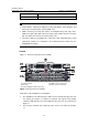
Installation Manual H3C S7500E Series Ethernet Switches z Chapter 1 Product Overview The two power modules, which sit in the upper part of the chassis provide 1+1 redundancy backup. See callout (1) in Figure 1-1. You can select either AC power supply or DC power supply. Figure 1-2 shows the rear panel of the S7502E.
Installation Manual H3C S7500E Series Ethernet Switches Chapter 1 Product Overview (1) Power modules (3) Fan tray (5) Jack for ESD-preventive wrist strap (2) SRPUs (in slot 0) (4) LPUs (in slot 1 and slot 2) Figure 1-3 Front panel of the S7503E-S All modules of the S7503E-S are hot swappable. z The S7503E-S has three horizontal slots. SRPUs are inserted into the upper slot. See callout (2) in Figure 1-3. Dedicated S7503E-S SRPUs are required. Different LPUs are inserted into the other two slots.
Installation Manual H3C S7500E Series Ethernet Switches Chapter 1 Product Overview There are two DC power input (PoE power supply input) terminals and two COM ports (monitor ports) on the rear panel of the chassis. III. S7503E Figure 1-5 shows the front panel of the S7503E.
Installation Manual H3C S7500E Series Ethernet Switches Chapter 1 Product Overview (5) (1) (4) (2) (3) (3) (1) Fan tray (3) Power module (5) SRPUs (in slot 0 and slot 1) (2) Jack for ESD-preventive wrist strap (4) LPUs (in slot 2 to slot 7) Figure 1-6 Front panel of the S7506E All the modules of the S7506E are hot swappable. z The S7506E has eight horizontal slots. SRPUs are inserted in the upper two slots (see callout (5) in Figure 1-6). SRPUs are required and support active-standby switchover.
Installation Manual H3C S7500E Series Ethernet Switches Chapter 1 Product Overview (1) (4) (5) (4) (2) (3) (3) (1) Fan tray (3) Power module (5) SRPUs (in slot 5 and slot 6) (2) Jack for ESD-preventive wrist strap (4) LPUs (in slot 0 to slot 4 and slot 7 to slot 11) Figure 1-7 Front panel of the S7510E All the modules of the S7510E are hot swappable. z The S7510E has twelve horizontal slots. SRPUs are inserted in the middle two slots (see callout (5) in Figure 1-7).
Installation Manual H3C S7500E Series Ethernet Switches Chapter 1 Product Overview VI. S7506E-V Figure 1-8 shows the front panel of the S7506E-V. (1) (6) (2) (5) (3) (4) (4) (1) Fan tray (3) Jack for ESD-preventive wrist strap (5) Air filter (2) LPUs (in slot 2 to slot 7) (4) Power module (6) SRPUs (in slot 0 and slot 1) Figure 1-8 Front panel of the S7506E-V All the modules of the switch are hot swappable. z The S7506E-V switch has eight vertical slots.
Installation Manual H3C S7500E Series Ethernet Switches Chapter 1 Product Overview active-standby switchover. Different LPUs are inserted in the other six slots (see callout (2) in Figure 1-8). z The fan tray is installed above the SRPUs and LPUs (see callout (1) in Figure 1-8) and the air flows up from the bottom. z The two power modules, which sit in the lower part of the chassis (see callout (3) in Figure 1-8), provide 1+1 redundancy backup. You can select either AC power supply or DC power supply.
Installation Manual H3C S7500E Series Ethernet Switches Chapter 1 Product Overview Table 1-4 Features of power modules Feature Description Protection functions Support input under-voltage protection, output over-voltage protection, short-circuit protection, over-current protection, and overheat protection 1+1 hot backup support Support 1 + 1 hot backup and current sharing Hot swap support Support hot swap with the power switch turned off while the device is in operation Typically, the S7502E and t
Installation Manual H3C S7500E Series Ethernet Switches Chapter 1 Product Overview Chassis (right) S7502E Power module (below) PSR2800-AC V N S7503ES N S7503E Y1 S7506E Y1 S7506EV S7510 E Y1 Y1 Note: z Y1 means that the power module directly fits the chassis. z Y2 means that you need to insert a power module adapter into the chassis and then inserting the power module into the power module adapter. z N means that the power module cannot be used in the chassis.
Installation Manual H3C S7500E Series Ethernet Switches Chapter 1 Product Overview Note: The PSR320-A uses a 10-A AC power cable. II. PSR320-D (1) Grounding screws (3) Negative terminal (–) of DC input (–48 V to –60 V) (5) Power LED (7) Captive screws (2) RTN terminal (+) of DC input (4) Power switch (6) Power module handle Figure 1-10 PSR320-D power module As shown in the figure, above the power switch is the power LED. If the power LED is green, the power supply operates normally.
Installation Manual H3C S7500E Series Ethernet Switches Chapter 1 Product Overview Above the power switch is the power LED. If the power LED is green, the power supply operates normally. If the LED is red, the power supply is abnormal. Table 1-8 Technical specifications of the PSR650-A power module Item Specifications Rated voltage range 100 VAC to 240 VAC; 50 Hz or 60 Hz Maximum output power 650 W Dimensions (H × W × D) 40 × 140 × 350 mm (1.57 × 5.51 × 13.78 in.
Installation Manual H3C S7500E Series Ethernet Switches Chapter 1 Product Overview V. PSR1400-A (2) (1) (3) (6) (4) (5) (1) Captive screws (3) Power LEDs (5) Power cable retainer (2) Power switch (4) AC power socket (6) Power module handle Figure 1-13 PSR1400-A power module On the right of the switch are the input LED, output LED, and fan LED. For their colors and descriptions, refer to section 7.2.3 “Troubleshooting PSR1400-A.
Installation Manual H3C S7500E Series Ethernet Switches Chapter 1 Product Overview VI. PSR1400-D (1) (2) (8) (3) (7) (4) (6) (5) (1) Captive screws (3) Power LEDs (5) RTN terminal (+) of DC input (7) System power switch (2) COM port for monitoring PoE (4) Negative terminal (–) of DC input (–48 V to –60 V) (6) Power module handle (8) PoE power switch Figure 1-14 PSR1400-D power module The PSR1400-D power module provides system power and PoE power.
Installation Manual H3C S7500E Series Ethernet Switches Chapter 1 Product Overview Table 1-11 Technical specifications of the PSR1400-D DC power module Item Specifications Rated voltage range –48 VDC to –60 VDC Maximum system output power 1400 W Maximum PoE output power 6720 W Dimensions (H × W × D) 128 × 196 × 380 mm (5.04 × 7.72 × 14.96 in.) VII.
Installation Manual H3C S7500E Series Ethernet Switches Chapter 1 Product Overview Caution: Keep the PoE power switch in the off position unless the device needs to offer PoE supply and is equipped with appropriate PoE-capable cards. On the right of the panel are the input LED, output LED, fan LED, PoE input LED, and PoE output LED. For the descriptions of these LEDs, refer to section 7.2.5 “Troubleshooting PSR2800-ACV.
Installation Manual H3C S7500E Series Ethernet Switches Chapter 1 Product Overview When the system power consumption of a switch (S7503E, S7506E, S7506E-V, or S7510E) is less than the maximum output power of a 1U power module, you can first insert the PWR-SPA power module adapters into the switch, and then insert 1U power modules into the power module adapters. By doing so, you can use the 1U-high power modules to power the switch.
Installation Manual H3C S7500E Series Ethernet Switches Chapter 1 Product Overview Model Power consumption (W) S7510E fan tray 50 S7506E-V fan tray 50 1.2.5 Air Filter Over a long period of time, dust may block the air filter at the air intake vent of the S7500E series. As a result, the heat dissipation of the system may be affected. You are recommended to clean the air filter every three months. Air filters are optional accessories.
Installation Manual H3C S7500E Series Ethernet Switches Chapter 1 Product Overview Chassis (right) S7502E S7503E -S S7503E S7506E S7510E S7506E -V No No Yes Yes Yes Yes Engine (below) LSQ1SRP12GB0 (Salience VI-GE) Note: The S7500E series, except the S7503E-S, are a dual-SRPU system. The SRPUs in a chassis must be of the same type. 1.3.2 LSQ1MPUA0 SRPU I. Applicable model S7502E II.
Installation Manual H3C S7500E Series Ethernet Switches Chapter 1 Product Overview III. Panel and LEDs Figure 1-18 shows the front panel of the LSQ1MPUA0. (1) CF card interface and CFS LED (2) Console port (3) 10/100Base-TX Ethernet port for management and LEDs (4) Power and fan tray status LEDs (5) LPU status LEDs (6) ACTIVE LED of LSQ1MPUA0 (7) RESET button Figure 1-18 Front panel of the LSQ1MPUA0 IV.
Installation Manual H3C S7500E Series Ethernet Switches Chapter 1 Product Overview Item Specifications Transmission distance 15 m (49.21 ft.) z z Functions z It can be connected to an ASCII terminal. It can be connected to a serial port of a local or remote (through a pair of modems) PC running terminal emulation program.
Installation Manual H3C S7500E Series Ethernet Switches Chapter 1 Product Overview Table 1-20 Description of the power status LEDs LED Description ON: The power module works normally. OK OFF: The power module is faulty or out of position. FAIL ON: The power module is faulty, or there is no power input to the power module, or the power switch is turned off. OFF: The power module is operational or out of position. Fan status LEDs z FAN: The LEDs show the status of the fan tray.
Installation Manual H3C S7500E Series Ethernet Switches Chapter 1 Product Overview VI. RESET button A reset button is provided on the LSQ1MPUA0 for you to reset the card when necessary. 1.3.3 Dedicated S7503E-S SRPU-LSQ1CGP24TSC0 I. Applicable model S7503E-S II. Technical specifications Table 1-23 Technical specifications of the LSQ1CGP24TSC0 Item Specifications CPU MIPS64, 400 MHz Boot ROM 512 KB Flash memory 64 MB DDR SDRAM 512 MB Dimensions (H × W × D) 45 × 377 × 355 mm (1.77 × 14.84 × 13.
Installation Manual H3C S7500E Series Ethernet Switches Chapter 1 Product Overview IV. On-board interfaces Optical Ethernet ports and Combo ports z The LSQ1CGP24TSC0 provides twenty-four 1000Base-X-SFP/100Base-FX-SFP ports and eight 10/100/1000Base-T GE ports. The eight GE ports and eight of the SFP ports can form eight Combo ports, each comprising a GE port and an SFP port.
Installation Manual H3C S7500E Series Ethernet Switches Chapter 1 Product Overview Note: In a Combo port, only one of the 1000Base-X-SFP/100Base-FX-SFP port and the 10/100/1000Base-T GE port can be used at a time. Each Ethernet port has a green LED. Table 1-26 describes the LEDs. Table 1-26 Description of the LED of each Ethernet port LED Description z LINK/ACT z z z OFF: No link is present. ON: A link is present. Blinking: Data is being transmitted or received.
Installation Manual H3C S7500E Series Ethernet Switches Chapter 1 Product Overview Table 1-28 Specifications of the 10/100Base-TX Ethernet port for management Item Specifications Connector type RJ-45 Number of connectors 1 Interface speed 10/100 Mbps, half/full duplex Connecting cable and maximum transmission distance Category-5 twisted pair, with a maximum transmission distance of 100 m (328.08 ft.
Installation Manual H3C S7500E Series Ethernet Switches Chapter 1 Product Overview Table 1-31 Description of the fan status LEDs LED z OK z FAIL z Description z z ON: The fans operate normally. OFF: The fans are faulty or out of position. ON: The fans are faulty or out of position. OFF: The fans operate normally. LPU status LEDs (SLOT0, SLOT1, and SLOT2) SLOT0, SLOT1, and SLOT2: The LPU status LEDs indicate the status of the LPUs seated in these three slots.
Installation Manual H3C S7500E Series Ethernet Switches Chapter 1 Product Overview II. Technical specifications Table 1-33 Technical specifications of the LSQ1SRP2XB0 Item Specifications CPU MIPS64, 600 MHz Boot ROM 512 KB Flash memory 64 MB DDR SDRAM 512 MB Dimensions (H × W × D) 45 × 377 × 355 mm (1.77 × 14.84 × 13.98 in.
Installation Manual H3C S7500E Series Ethernet Switches Chapter 1 Product Overview Table 1-34 Description of the CFS LED Status z Description OFF No CF card is in position. ON The CF card is in position. 10GBase-R-XFP Ethernet ports Table 1-35 Specifications of the 10GBase-R-XFP Ethernet ports Item Specifications Connector type LC Number of interfaces 2 Interface standard 10GBase-R Applicable fiber module Refer to “Appendix A List of Pluggable Modules.
Installation Manual H3C S7500E Series Ethernet Switches Chapter 1 Product Overview Item Specifications z z Functions z It can be connected to an ASCII terminal. It can be connected to a serial port of a local or remote (through a pair of modems) PC running terminal emulation program.
Installation Manual H3C S7500E Series Ethernet Switches Chapter 1 Product Overview Table 1-40 Description of the power status LEDs LED Description ON: The power modules operate normally. OK OFF: The power module is faulty or out of position. ON: At least one power module is faulty or switched off. FAIL OFF: The power modules are operational or out of position. Fan status LEDs z FAN: The LEDs show the status of the fan tray.
Installation Manual H3C S7500E Series Ethernet Switches Chapter 1 Product Overview VI. RESET button A reset button is provided on the LSQ1SRP2XB0 for you to reset the card when necessary. 1.3.5 Salience VI SRPU-LSQ1SRPB0 I. Applicable models z S7503E z S7506E z S7510E z S7506E-V II.
Installation Manual H3C S7500E Series Ethernet Switches Chapter 1 Product Overview IV. On-board interfaces z CF card slot The CF card slot can accommodate a standard CF card (Type I or Type II), where you can store host software and logs, and thus upgrade software conveniently. The CF card is hot swappable. Table 1-44 describes the CFS LED on the right of the CF card. Table 1-44 Description of the CFS LED Status z Description OFF No CF card is in position. ON The CF card is in position.
Installation Manual H3C S7500E Series Ethernet Switches Chapter 1 Product Overview Table 1-46 Specifications of the 10/100Base-TX Ethernet port Item Specifications Connector type RJ-45 Number of interfaces 1 Interface speed 10/100 Mbps, half/full duplex Connecting cable and maximum transmission distance Category-5 twisted pair, with a maximum transmission distance of 100 m (328.08 ft.
Installation Manual H3C S7500E Series Ethernet Switches Chapter 1 Product Overview Table 1-49 Description of the fan status LEDs LED Description z OK z z FAIL z z ON: The fans operate normally. OFF: The fans are faulty or out of position. ON: The fans are faulty or out of position. OFF: The fans operate normally. LPU status LEDs (SLOT0 through SLOT11) SLOT1 through SLOT11: The LPU status LEDs indicate the status of the LPUs seated in the twelve slots.
Installation Manual H3C S7500E Series Ethernet Switches Chapter 1 Product Overview II. Technical specifications Table 1-51 Technical specifications of LSQ1SRP1CB0 Item Specifications CPU MIPS64, 600 MHz Boot ROM 512 KB Flash memory 64 MB DDR SDRAM 512 MB Card physical dimensions (H x W x D) 45.1 × 377 × 355 mm (1.77 × 14.84 × 13.98 in.
Installation Manual H3C S7500E Series Ethernet Switches Chapter 1 Product Overview Table 1-52 Description of the CFS LED Status z Description OFF No CF card is in position. ON The CF card is in position.
Installation Manual H3C S7500E Series Ethernet Switches Chapter 1 Product Overview Item Specifications Used for switch software upgrade and network management Function Table 1-55 describes the status LEDs of the 10/100Base-TX management Ethernet port. Table 1-55 Description of the status LEDs of the 10/100Base-TX Ethernet port LED Description z LINK z z ACT z OFF: No link is present. ON: A link is present. OFF: No data is being transmitted or received.
Installation Manual H3C S7500E Series Ethernet Switches Chapter 1 Product Overview Table 1-57 Description of the fan status LEDs LED z OK z z FAIL z Description z ON: The fans operate normally. OFF: The fans are faulty or out of position. ON: The fans are faulty or out of position. OFF: The fans operate normally. LPU status LEDs (SLOT0 through SLOT11) SLOT0 through SLOT11: The LEDs indicate the status of the LPUs seated in the twelve slots.
Installation Manual H3C S7500E Series Ethernet Switches Chapter 1 Product Overview II. Technial specifications Table 1-59 Technical specifications of the LSQ1MPUB0 Item Specifications CPU MIPS64, 600 MHz Boot ROM 512 KB Flash memory 64 MB DDR SDRAM 512 MB Dimensions (H x W x D) 45 × 377 × 355 mm (1.77 × 14.84 × 13.98 in.
Installation Manual H3C S7500E Series Ethernet Switches Chapter 1 Product Overview Table 1-60 Specifications of the console port Item Specifications Connector type RJ-45 Number of connectors 1 Interface standard Asynchronous EIA/TIA-232 Baud rate 115,200 bps (defaulting to 9,600 bps) Transmission distance 15 m (49.21 ft.) z z Functions It can be connected to an ASCII terminal.
Installation Manual H3C S7500E Series Ethernet Switches Chapter 1 Product Overview V. System LEDs System status LEDs z The LEDs on the card panel indicate the statuses of the power modules, fans, LPUs seated in the twelve slots, and LSQ1MPUB0 itself. Power status LEDs z PWR: The power status LEDs show the status of the power modules. Table 1-63 Description of the power status LEDs LED Description ON: The power modules operate normally. OK OFF: The power module is faulty or out of position.
Installation Manual H3C S7500E Series Ethernet Switches Chapter 1 Product Overview Note: If the RUN LED flashes at a high frequency, the card is in the startup process, but is not yet operational. At system startup, the ALM LED will be ON for a while, but it does not mean that the card is faulty. z ACTIVE LED The ACTIVE LED shows the active/standby status of the LSQ1MPUB0. If the ACTIVE LED is ON, the LSQ1MPUB0 is active; if OFF, the LSQ1MPUB0 is standby. VI.
Installation Manual H3C S7500E Series Ethernet Switches Chapter 1 Product Overview III. Panel and LEDs Figure 1-24 shows the front panel of the LSQ1SRPD0. (1) CF card slot and CF card status LED (3) 10/100Base-TX management Ethernet port and LEDs (5) LPU status LEDs (7) RESET button (2) Console port (4)Power module and fan status LEDs (6) ACTIVE LED of LSQ1SRPD0 Figure 1-24 Front panel of the LSQ1SRPD0 IV.
Installation Manual H3C S7500E Series Ethernet Switches Chapter 1 Product Overview Table 1-68 Specifications of the 10/100Base-TX management Ethernet port Item Specifications Connector type RJ-45 Number of interfaces 1 Interface speed 10/100 Mbps, half/full duplex Cable medium and maximum transmission distance Category-5 twisted pair, with a maximum transmission distance of 100 m (328.08 ft.
Installation Manual H3C S7500E Series Ethernet Switches Chapter 1 Product Overview Table 1-71 Description of the fan status LEDs LED z OK z FAIL z Description z z ON: The fans operate normally. OFF: The fans are faulty or out of position. ON: The fans are faulty or out of position. OFF: The fans operate normally. LPU status LEDs (SLOT0 through SLOT11) SLOT0 through SLOT11: The LEDs indicate the status of the LPUs seated in the twelve slots.
Installation Manual H3C S7500E Series Ethernet Switches Chapter 1 Product Overview II. Technial specifications Table 1-73 Technical specifications of the LSQ1SR12GB0 Item Specifications Dual CPUs: CPU z z MIPS64, 600 MHz MIPS64, 400 MHz Boot ROM 512 KB Flash memory 64 MB DDR SDRAM 512 MB Dimensions (H x W x D) 45 × 377 × 355 mm (1.77 × 14.84 × 13.98 in.
Installation Manual H3C S7500E Series Ethernet Switches Chapter 1 Product Overview Table 1-74 Description of the CFS LED Status z Description OFF No CF card is in position. ON The CF card is in position. GE/FE SFP ports Table 1-75 presents the specifications of the GE/FE ports. Table 1-75 Specifications of the GE/FE SFP ports Item Specifications Connector type SFP Number of connectors 12 z z Standards z z z z Pluggable module type IEEE 802.3-2005 IEEE 802.1D-2004 IEEE 802.
Installation Manual H3C S7500E Series Ethernet Switches Chapter 1 Product Overview Table 1-77 Specifications of the console port Item Specifications Connector type RJ-45 Number of connectors 1 Interface standard Asynchronous EIA/TIA-232 Baud rate 115,200 bps (defaulting to 9,600 bps) Transmission distance 15 m (49.21 ft.) z z Functions It can be connected to an ASCII terminal.
Installation Manual H3C S7500E Series Ethernet Switches Chapter 1 Product Overview V. System LEDs System status LEDs z The LEDs on the card panel indicate the statuses of the power modules, fans, LPUs seated in the twelve slots, and LSQ1SR12GB0 itself. Power status LEDs z PWR: The power status LEDs show the status of the power modules. Table 1-80 Description of the power status LEDs LED Description ON: The power modules operate normally. OK OFF: The power module is faulty or out of position.
Installation Manual H3C S7500E Series Ethernet Switches Chapter 1 Product Overview Note: If the RUN LED flashes at a high frequency, the card is in the startup process, but is not yet operational. At system startup, the ALM LED will be ON for a while, but it does not mean that the card is faulty. ACTIVE LED z The ACTIVE LED shows the active/standby status of the LSQ1SR12GB0. If the ACTIVE LED is ON, the LSQ1SR12GB0 is active; if OFF, the LSQ1SR12GB0 is standby. VI.
Installation Manual H3C S7500E Series Ethernet Switches Chapter 1 Product Overview II. Panel and LEDs Figure 1-26 LSQ1FP48SA0 panel Each 100M Ethernet optical port has a green LED. Table 1-84 describes the LED. Table 1-84 Description of the LED of each port on the LSQ1FP48SA0 panel LED Description z LINK/ACT z z OFF: No link is present. ON: A link is present. Blinking: Data is being transmitted or received. 1.4.2 LSQ1FV48SA0 I.
Installation Manual H3C S7500E Series Ethernet Switches Chapter 1 Product Overview II. Panel and LEDs Figure 1-27 LSQ1FV48SA0 panel Each 10/100M auto-sensing Ethernet electrical port has a green LED. Table 1-86 describes the LED. Table 1-86 Description of the LED of each port on the LSQ1FV48SA0 panel LED Description z LINK/ACT z z OFF: No link is present. ON: A link is present. Blinking: Data is being transmitted or received. 1.4.3 LSQ1GP12EA0 I.
Installation Manual H3C S7500E Series Ethernet Switches Chapter 1 Product Overview II. Panel and LEDs Figure 1-28 LSQ1GP12EA0 panel Each 1000Base-X-SFP Ethernet port has a green LED. Table 1-88 describes the LED. Table 1-88 Description of the LED of each port on the LSQ1GP12EA0 panel LED Description z LINK/ACT z z OFF: No link is present. ON: A link is present. Blinking: Data is being transmitted or received. 1.4.4 LSQ1GP12SC0 I.
Installation Manual H3C S7500E Series Ethernet Switches Chapter 1 Product Overview II. Panel and LEDs Figure 1-29 LSQ1GP12SC0 panel Each 1000Base-X-SFP/100Base-FX-SFP Ethernet port has a green LED. Table 1-90 describes the LED. Table 1-90 Description of the LED of each port on the LSQ1GP12SC0 panel LED Description z LINK/ACT z z OFF: No link is present. ON: A link is present. Blinking: Data is being transmitted or received. 1.4.5 LSQ1GP24SC0 I.
Installation Manual H3C S7500E Series Ethernet Switches Chapter 1 Product Overview Item Specifications z z Standards z z IEEE 802.3-2005 IEEE 802.1D-2004 IEEE 802.1Q-2003 IEEE802.1X-2004 II. Panel and LEDs Figure 1-30 LSQ1GP24SC0 panel Each 1000Base-X-SFP/100Base-FX-SFP Ethernet port has a green LED. Table 1-92 describes the LED. Table 1-92 Description of the LED of each port on the LSQ1GP24SC0 panel LED Description z LINK/ACT z z OFF: No link is present. ON: A link is present.
Installation Manual H3C S7500E Series Ethernet Switches Chapter 1 Product Overview Item Specifications z z Pluggable module type Gigabit SFP module 100 Mbps SFP module Refer to “Appendix A List of Pluggable Modules.” z z Standard z z IEEE 802.3-2005 IEEE 802.1D-2004 IEEE 802.1Q-2003 IEEE802.1X-2004 II. Panel and LEDs Figure 1-31 LSQ1GP48SC0 panel Each 1000Base-X-SFP/100Base-FX-SFP Ethernet port has a green LED. Table 1-94 describes the LED.
Installation Manual H3C S7500E Series Ethernet Switches Chapter 1 Product Overview Item Specifications Number of ports 24 z Interface speed z Cable medium and maximum transmission distance Category-5 twisted pair cables, with a maximum transmission distance of 100 m (328.08 ft.) z z Standards 10/100/1000 Mbps, half/full duplex MDI/MDI-X auto-sensing z z IEEE 802.3-2005 IEEE 802.1D-2004 IEEE 802.1Q-2003 IEEE802.1X-2004 II.
Installation Manual H3C S7500E Series Ethernet Switches Chapter 1 Product Overview Item Specifications Power consumption 60 W to 80 W Connector type RJ-45 Number of ports 48 z Interface speed z Cable medium and maximum transmission distance Category-5 twisted pair cables, with a maximum transmission distance of 100 m (328.08 ft.) z z Standards 10/100/1000 Mbps, half/full duplex MDI/MDI-X auto-sensing z z IEEE 802.3-2005 IEEE 802.1D-2004 IEEE 802.1Q-2003 IEEE802.1X-2004 II.
Installation Manual H3C S7500E Series Ethernet Switches Chapter 1 Product Overview Item Specifications DDR SDRAM 512 MB Dimensions (H x W x D) 40 × 377 × 355 mm (1.57 × 14.84 × 13.98 in.) Power consumption 60 W to 90 W Connector type RJ-45 Number of ports 48 z Interface speed z Cable medium and maximum transmission distance 10/100/1000 Mbps, half/full duplex MDI/MDI-X auto-sensing Category-5 twisted pair cables, with a maximum transmission distance of 100 m (328.08 ft.
Installation Manual H3C S7500E Series Ethernet Switches Chapter 1 Product Overview Table 1-101 Technical specifications of the LSQ1P24XGSC0 Item Specifications CPU MIPS64, 400 MHz Boot ROM 512 KB DDR SDRAM 512 MB Dimensions (H x W x D) 40 × 377 × 355 mm (1.57 × 14.84 × 13.98 in.
Installation Manual H3C S7500E Series Ethernet Switches Chapter 1 Product Overview Table 1-103 Description of the LEDs of the 10GBase-R-XFP Ethernet port LED Description z LINK z z ACT z OFF: No link is present. ON: A link is present. OFF: No data is being transmitted or received. Blinking: Data is being transmitted or received. 1.4.11 LSQ1T24XGSC0 I. Introduction The LSQ1T24XGSC0 provides 24 auto-sensing 10/100/1000Base-T Ethernet ports and two 10GBase-R-XFP Ethernet ports.
Installation Manual H3C S7500E Series Ethernet Switches Chapter 1 Product Overview II. Panel and LEDs Figure 1-36 LSQ1T24XGSC0 panel Each auto-sensing 10/100/1000Base-T Ethernet port has a green LED. Table 1-105 describes the LED. Table 1-105 Description of the LED of the auto-sensing 10/100/1000Base-T Ethernet port LED Description z LINK/ACT z z OFF: No link is present. ON: A link is present. Blinking: Data is passing through the port. Each 10GBase-R-XFP Ethernet port has two LEDs.
Installation Manual H3C S7500E Series Ethernet Switches Chapter 1 Product Overview Item Specifications Number of ports 1 Interface speed 10 Gbps Pluggable module type 10G XFP module Refer to “Appendix A List of Pluggable Modules.” z z Standards z z IEEE 802.3-2005 IEEE 802.1D-2004 IEEE 802.1Q-2003 IEEE802.1X-2004 II. Panel and LEDs Figure 1-37 LSQ1TGX1EA0 panel The 10GBase-R-XFP Ethernet port has two green LEDs. Table 1-108 describes the LEDs.
Installation Manual H3C S7500E Series Ethernet Switches Chapter 1 Product Overview Item Specifications Power consumption 30 W to 40 W Connector type LC Number of ports 2 Interface speed 10 Gbps Pluggable module type 10G XFP module Refer to “Appendix A List of Pluggable Modules.” z z Standards z z IEEE 802.3-2005 IEEE 802.1D-2004 IEEE 802.1Q-2003 IEEE802.1X-2004 II. Panel and LEDs Figure 1-38 LSQ1TGX2SC0 panel Each 10GBase-X-XFP Ethernet port has two green LEDs.
Installation Manual H3C S7500E Series Ethernet Switches Chapter 1 Product Overview Table 1-111 Technical specifications of the LSQ1GP24TSC0 Item Specifications CPU MIPS64, 400 MHz Boot ROM 512 KB DDR SDRAM 512 MB Dimensions (H x W x D) 40 × 377 × 355 mm (1.57 × 14.84 × 13.98 in.
Installation Manual H3C S7500E Series Ethernet Switches Chapter 1 Product Overview 1000Base-X-SFP/100Base-FX-SFP Ethernet port number 10/100/1000Base-T GE port number 23 31 24 32 Note: In a Combo port, only one of the 1000Base-X-SFP/100Base-FX-SFP port and the 10/100/1000Base-T GE port can be used at a time. II. Panel and LEDs Figure 1-39 LSQ1GP24TSC0 panel Each Ethernet port has one green LED. Table 1-113 describes the LEDs on the LSQ1GP24TSC0 panel.
Installation Manual H3C S7500E Series Ethernet Switches Chapter 1 Product Overview Item Specifications Power consumption 41 W to 95 W z Connector type z Number of ports SFP RJ-45 40 RJ-45 + 8 SFP z Interface speed z z z Pluggable module type z Electrical GE port: 10/100/1000 Mbps Gigabit SFP port: 100/1000 Mbps Gigabit SFP module 100 Mbps SFP module Auto-sensing 10/100/1000Base-T Ethernet port Refer to “Appendix A List of Pluggable Modules.” z z Standards z z IEEE 802.3-2005 IEEE 802.
Installation Manual H3C S7500E Series Ethernet Switches Chapter 1 Product Overview Table 1-116 Technical specifications of the LSQ1PT4PSC0 Item Specifications CPU MIPS64, 400 MHz Boot ROM 512 KB DDR SDRAM 512 MB Dimensions (H x W x D) 40 × 377 × 355 mm (1.57 × 14.84 × 13.98 in.
Installation Manual H3C S7500E Series Ethernet Switches Chapter 1 Product Overview EPON port status LED status ON UP Description An ONU is registered. Likewise, each 1000Base-X-SFP/100Base-FX-SFP Ethernet port has a green LED. Table 1-118 describes the LED of each 1000Base-X-SFP/100Base-FX-SFP Ethernet port. Table 1-118 Description of the LED of each 1000Base-X-SFP/100Base-FX-SFP Ethernet port LED Description z LINK/ACT z z OFF: No link is present. ON: A link is present.
Installation Manual H3C S7500E Series Ethernet Switches Chapter 1 Product Overview Item Specifications z z Pluggable module type z Pluggable modules for EPON interfaces Gigabit SFP module 100 Mbps SFP module Refer to “Appendix A List of Pluggable Modules.” z z Standards z z IEEE 802.3-2005 IEEE 802.1D-2004 IEEE 802.1Q-2003 IEEE802.1X-2004 II. Panel and LEDs Figure 1-42 LSQ1PT8PSC0 panel Each EPON port has a green LED. Table 1-120 describes the LED of each EPON port.
Installation Manual H3C S7500E Series Ethernet Switches Chapter 1 Product Overview 1.4.18 LSQ1PT16PSC0 I. Introduction The LSQ1PT16PSC0 provides sixteen EPON ports and eight 1000Base-X-SFP/ 100Base-FX-SFP Ethernet ports. Table 1-122 Technical specifications of the LSQ1PT16PSC0 Item Specifications CPU MIPS64, 400 MHz Boot ROM 512 KB DDR SDRAM 512 MB Dimensions (H x W x D) 40 × 377 × 355 mm (1.57 × 14.84 × 13.98 in.
Installation Manual H3C S7500E Series Ethernet Switches Chapter 1 Product Overview Table 1-123 Description of the EPON port status and the LED status of the LSQ1PT16PSC0 LED status EPON port status Description OFF Down No SFP module is installed. OFF UP An SFP module is installed but no ONU is registered. ON UP An ONU is registered. Likewise, each 1000Base-X-SFP/100Base-FX-SFP Ethernet port has a green LED. Table 1-124 describes the LED of each 1000Base-X-SFP/100Base-FX-SFP Ethernet port.
Installation Manual H3C S7500E Series Ethernet Switches Chapter 1 Product Overview II. Switch model Table 1-125 List of the S7500E series models Description Quantity Remarks S7502E switch 1 Optional S7503E-S switch 1 Optional S7503E switch 1 Optional S7506E switch 1 Optional S7510E switch 1 Optional S7506E-V switch 1 Optional III.
Installation Manual H3C S7500E Series Ethernet Switches Chapter 1 Product Overview 1.5.2 Purchasing SRPUs Table 1-127 List of SRPUs for the S7500E series Type Quantity Remarks Required LSQ1MPUA0 1 to 2 LSQ1CGP24TSC0 1 Salience VI-10GE 1 to 2 Required Salience VI 1 to 2 Required Salience VI-Turbo 1 to 2 Required Salience VI-Lite 1 to 2 Required Salience VI-Plus 1 to 2 Required Salience VI-GE 1 to 2 Required For S7502E only Required For S7503E-S only 1.5.
Installation Manual H3C S7500E Series Ethernet Switches Chapter 1 Product Overview Type Quantity Remarks LSQ1P24XGSC0 Determined by the number of LPU slots provided by the chassis Optional LSQ1T24XGSC0 Determined by the number of LPU slots in the chassis Optional LSQ1TGX1EA0 Determined by the number of LPU slots in the chassis Optional LSQ1TGX2SC0 Determined by the number of LPU slots in the chassis Optional LSQ1GP24TSC0 Determined by the number of LPU slots in the chassis Optional LSQ1P
Installation Manual H3C S7500E Series Ethernet Switches Chapter 1 Product Overview 1.5.
Installation Manual H3C S7500E Series Ethernet Switches Tables of Contents Table of Contents Chapter 2 Installation Preparations............................................................................................. 2-1 2.1 Safety Instructions ............................................................................................................. 2-1 2.1.1 General Instructions ................................................................................................ 2-1 2.1.
Installation Manual H3C S7500E Series Ethernet Switches Chapter 2 Installation Preparations Chapter 2 Installation Preparations 2.1 Safety Instructions To avoid damage to human body and devices, please read the following safety recommendations carefully before installing the S7500E series. The recommendations do not cover every possible hazardous condition. 2.1.1 General Instructions z Turn OFF all the powers and remove all the power cables before opening the chassis.
Installation Manual H3C S7500E Series Ethernet Switches Chapter 2 Installation Preparations Caution: Hold the handles on both sides of the chassis, instead of power handles or the vent of the chassis when moving the switch. Since the power handle or the vent is not designed to bear the weight of the entire chassis, the switch may get damaged or even your body may get hurt if you hold these parts to move the switch. 2.1.
Installation Manual H3C S7500E Series Ethernet Switches Chapter 2 Installation Preparations 2.1.5 Laser Safety Some LPUs of the S7500E series have optical interfaces. In operating status, it is prohibited to stare into the open optical interface because the laser being transmitted through the optical fiber will produces a small beam of light, it has very high power density and is invisible to human eyes, when a beam of light enters the eye, retina may be burned.
Installation Manual H3C S7500E Series Ethernet Switches Chapter 2 Installation Preparations 2.2.2 Cleanness Requirements Dust is a big harm for the normal operation of the switch. The indoor dust accumulated on the chassis can cause electrostatic adsorption, resulting in the poor contact of the connector or metal contact point. This happens more frequently when the relative indoor humidity is low, which will not only shorten the service life of the switch, but also cause communication failure.
Installation Manual H3C S7500E Series Ethernet Switches z Chapter 2 Installation Preparations Keep the switch far away from the radio launcher, radar launcher, and high-frequency devices working in high currents. If necessary, adopt electromagnetic shield. 2.2.4 Grounding Requirements A good grounding system is the basis for a switch to work stably and reliably and the important guarantee of lightning protection, anti-interference and ESD.
Installation Manual H3C S7500E Series Ethernet Switches Chapter 2 Installation Preparations 2.
Installation Manual H3C S7500E Series Ethernet Switches Tables of Contents Table of Contents Chapter 3 Hardware Installation .................................................................................................. 3-1 3.1 Confirming Installation Preparations.................................................................................. 3-1 3.2 Installation Flowchart ......................................................................................................... 3-1 3.
Installation Manual H3C S7500E Series Ethernet Switches Chapter 3 Hardware Installation Chapter 3 Hardware Installation Note: The S7500E series are designed for indoor application. 3.1 Confirming Installation Preparations z Make sure that you have read Chapter 2 carefully z All requirements introduced in Chapter 2 are satisfied. 3.
Installation Manual H3C S7500E Series Ethernet Switches Chapter 3 Hardware Installation 3.3 Mounting a Switch to the Designated Position 3.3.1 Mounting a Switch into a Cabinet After purchasing an S7500E Ethernet switch, you can mount the switch into an H3C N68 cabinet or a standard 19” cabinet. The installation methods are similar. The following describes how to mount a switch into an N68 cabinet. Figure 3-2 Mount a switch into an N68 cabinet I.
Installation Manual H3C S7500E Series Ethernet Switches 2) Chapter 3 Hardware Installation Mount weight-bearing guide rails on the N68 cabinet based on the installation position of the switch. (Two types of weight-bearing guide rails are available. One is small guide rails and applicable to the S7502E and S7503E-S. The other is large guide rails and applicable to the S7500E series other than the S7502E and S7503E-S.) 3) Mount the cable rack and mounting ears on the switch.
Installation Manual H3C S7500E Series Ethernet Switches Chapter 3 Hardware Installation Note: z The S7500E series provide dual grounding screws in compliance with the NEBS standard to deliver high reliability. z Generally, the cabinet has a grounding strip. The grounding cable of the switch can be connected to the grounding strip of the cabinet. II. Other grounding environment Note: The following figures are sketch maps, and just show the way of cable connecting rather than the real layouts.
Installation Manual H3C S7500E Series Ethernet Switches Chapter 3 Hardware Installation Ethernet Switch Grounding screw Power input Protection grounding cable Ground Angle steel Figure 3-4 Connect the protection grounding cable to the grounding body nearby z If there is no grounding strip and no grounding body can be buried, the AC-powered Ethernet switch can be grounded through the PE wire of the AC power supply.
Installation Manual H3C S7500E Series Ethernet Switches Chapter 3 Hardware Installation Ethernet Switch AC/DC power box - 48V strip RTN strip - 48V RTN DC power input PGND strip Grounding screw Ground Figure 3-6 Ground a DC-powered Ethernet switch through the RTN wire of a power cabinet 3.5 Installing Switch Modules For the procedure for installing cards, power modules, and fan tray, refer to Chapter 5 “Hardware Maintenance”. 3.6 Connecting the Power Cable 3.6.1 Connecting the AC Power Cable I.
Installation Manual H3C S7500E Series Ethernet Switches Chapter 3 Hardware Installation Figure 3-8 Connect the AC power cable for the PSR320-A (II) To connect the AC power cable for the PSR320-A, proceed as follows: 1) Plug one end of the AC power cable into the socket on the switch and lock the cable with the power cable retainer. 2) Plug the other end into the AC power socket strip, which is connected to the AC power supply in the equipment room. II. PSR650-A power module Refer to section 3.6.1 I.
Installation Manual H3C S7500E Series Ethernet Switches 3) Chapter 3 Hardware Installation Plug the other end into the AC power socket strip, which is connected to the AC power supply in the equipment room. IV. PSR2800-ACV power module There are two AC power inputs on the PSR2800-ACV power module, one for system power and the other for PoE power. The connection of the power cable for each power input is the same as that of the PSR1400-A. For the detailed connection method, refer to section 3.6.1 III.
Installation Manual H3C S7500E Series Ethernet Switches Chapter 3 Hardware Installation 2) Loosen the fastening screw on the wiring terminal with a Phillips screwdriver. 3) Connect the end of the blue DC power cable marked with – to the negative terminal (–) on the power module and fasten the screw. 4) Connect the end of the black DC power cable marked with + to the RTN (+) terminal on the power module and fasten the screw. 5) Put the protection cover on the wiring terminals.
Installation Manual H3C S7500E Series Ethernet Switches 1) Chapter 3 Hardware Installation Loosen the fastening screws on the protection cover with a Phillips screwdriver and remove the protection cover. There are two flat washers, one spring washer, and one fastening nut M6 from inside to outside on each wiring terminal. 2) Loosen the fastening nut on four wiring terminals with a socket wrench M6 and remove the fastening nut, spring washer and one flat washer in turn.
Installation Manual H3C S7500E Series Ethernet Switches Chapter 3 Hardware Installation Note: z When you use PSR1400-D modules to provide PoE supply to attached devices and there are more than three PoE-capable LPUs in the switch, you are recommended to use 0AWG cables with a cross section area of 50 mm2 to ensure the steady and safe operation of the switch.
Installation Manual H3C S7500E Series Ethernet Switches 1) Chapter 3 Hardware Installation Remove the protection cover from the terminals which are used to connect the external PoE power supply. 2) Use a socket wrench M5 to loosen the fastening nut on the input terminal of the switch, and a socket wrench M8 to loosen the fastening nut on the output terminal of the external PoE power supply.
Installation Manual H3C S7500E Series Ethernet Switches Chapter 3 Hardware Installation Table 3-1 Console cable pinouts Pin (RJ-45) Signal Pin (DB-9) Signal 1 RTS 8 CTS 2 DTR 6 DSR 3 TXD 2 RXD 4 SG 5 SG 5 SG 5 SG 6 RXD 3 TXD 7 DSR 4 DTR 8 CTS 7 RTS II. Connecting the console cable Take the following steps to connect the console cable, when configuring the switch on the terminal.
Installation Manual H3C S7500E Series Ethernet Switches Chapter 3 Hardware Installation 3.7.3 Connecting the COM Cable I. Introduction When connected to an external PoE power supply, the S7500E series can monitor the running status of the external PoE power supply through the COM port. The COM ports (one RS-485 port and one RS-232 port) of the S7502E and the S7503E-S are located on the rear panel of the chassis.
Installation Manual H3C S7500E Series Ethernet Switches Chapter 3 Hardware Installation Figure 3-15 RJ-45 connector Table 3-2 RJ-45 MDI interface pinouts 10Base-T/100Base-TX 1000Base-T Pin Signal Function Signal Function 1 Tx+ Send data BIDA+ Bi-directional data cable A+ 2 Tx- Send data BIDA- Bi-directional data cable A- 3 Rx+ Receive data BIDB+ Bi-directional data cable B+ 4 Reserved — BIDC+ Bi-directional data cable C+ 5 Reserved — BIDC- Bi-directional data cable C- 6 Rx-
Installation Manual H3C S7500E Series Ethernet Switches Chapter 3 Hardware Installation 10Base-T/100Base-TX 1000Base-T Pin Signal Function Signal Function 5 Reserved — BIDD- Bi-directional data cable D- 6 Tx- Send data BIDA- Bi-directional data cable A- 7 Reserved — BIDC+ Bi-directional data cable C+ 8 Reserved — BIDC- Bi-directional data cable C- Note: Pins 1 and 2 (negative), 3 and 6 (positive) are used for external PoE power supply. II.
Installation Manual H3C S7500E Series Ethernet Switches Chapter 3 Hardware Installation Figure 3-17 LC connector II. Connecting fibers 1) Remove the protective cap from the connector of the fiber and clean the surface of the fiber. 2) Remove the protective cap from the optical interface of the switch, and plug one end of the fiber into this interface. Step 3: Connect the other end of the fiber connector to the corresponding device.
Installation Manual H3C S7500E Series Ethernet Switches Chapter 3 Hardware Installation equipment room (whether the signal cable of the room is accessed from the cabling rack on the top of the chassis or the cabling rack under the floor.) Collect all the transit data signal cable connectors and locate them on the floor of the chassis (instead of any places outside the chassis for fear of unexpected damage).
Installation Manual H3C S7500E Series Ethernet Switches Chapter 3 Hardware Installation 3.9.2 Precautions for Cable Binding z Bind the cables straight in the cabinet. No twisting or bending. Figure 3-18 Cable binding example I z The radius of the curve at which a cable is bent should be at least twice the cable’s diameter. At the point where a cable runs out of a connector, the radius of the curve at which the cable is bent should be at least five times its diameter.
Installation Manual H3C S7500E Series Ethernet Switches Chapter 3 Hardware Installation Figure 3-19 Cable binding example II z Before bending the cables, bind them first. Mind that no tie binds the bended part of any cables, for fear of cable core breaking due to excessive stress. See the following figure. Figure 3-20 Cable binding example III z The spare cables or excessive parts should be folded and bound and located at right places in a cabinet or on the cable channel.
Installation Manual H3C S7500E Series Ethernet Switches (1) (2) Chapter 3 Hardware Installation (3) (4) (1) Flat washer (3) Spring washer (2) Flat washer (4) Fastening nut Figure 3-21 Cable fixing example z Fix the terminal of harder power cables to free the terminal and the cable from stress; z No tapping screw can be used to fasten the cabling terminals; z The power cables of the same type and in the same direction should be bound together and kept clean and straight; Follow the parameters de
Installation Manual H3C S7500E Series Ethernet Switches Chapter 3 Hardware Installation 3.10 Checking the Installation Caution: Confirm that you have turned off the power before check; otherwise, improper connection will hurt people or the component of the switch. After installing the switch, please check if the items listed in the following table are normal.
Installation Manual H3C S7500E Series Ethernet Switches Table of Contents Table of Contents Chapter 4 System Commissioning .............................................................................................. 4-1 4.1 Configuration Environment Setup...................................................................................... 4-1 4.1.1 Setting up Networking Environment........................................................................ 4-1 4.1.2 Connecting the Console Cable ...........
Installation Manual H3C S7500E Series Ethernet Switches Chapter 4 System Commissioning Chapter 4 System Commissioning 4.1 Configuration Environment Setup 4.1.1 Setting up Networking Environment z A terminal (a PC in this example) is connected to the console port of the switch with a console cable. Switch Connected to the console port of the switch Connected to the serial port of a PC Console cable PC Figure 4-1 Switch configuration networking 4.1.
Installation Manual H3C S7500E Series Ethernet Switches 1) Chapter 4 System Commissioning Start PC and run the terminal emulator (such as Terminal on Windows3.1, and the HyperTerminal on Windows95/Windows98/Windows 2000/Windows NT/Windows ME/Windows XP). 2) Set the parameters for Windows XP HyperTerminal as follows: z Bits per second: 9600 z Data bits: 8.
Installation Manual H3C S7500E Series Ethernet Switches Chapter 4 System Commissioning Figure 4-3 Set serial port for HyperTerminal connection After selecting serial ports, click OK. The following interface will pop up for setting serial port parameters. Set bits per second to 9600, data bits to 8, parity to none, stop bits to 1 and flow control to none.
Installation Manual H3C S7500E Series Ethernet Switches Chapter 4 System Commissioning After setting serial port parameters, click OK. Then the system will enter the HyperTerminal dialogue box as shown in the following figure. Figure 4-5 HyperTerminal interface In the above dialogue box, select Properties and enter the window. Click the Settings tab to set the attributes (see the following figure). In this interface, select the terminal emulation to VT100 and then click OK.
Installation Manual H3C S7500E Series Ethernet Switches Chapter 4 System Commissioning Figure 4-6 Set terminal emulation in the property setting window 4.2 Power-On Startup 4.2.1 Check before Power-On Before powering on an Ethernet Switch, check if: z The switch has been mounted steadily. z All the cards have been correctly installed. z All the communication cables, fibers, power cables, and grounding cables have been correctly connected.
Installation Manual H3C S7500E Series Ethernet Switches Chapter 4 System Commissioning Caution: Before powering on the switch, make sure where the power switch of the equipment room is located, so that you will be able to power off when meeting accidence. 4.2.2 Power-On z Turn on the power supply of the switch. z Power on the switch. 4.2.3 Check after Power-On (Recommended) You are recommended to check as follows after powering on the switch to ensure the configurations thereafter.
Installation Manual H3C S7500E Series Ethernet Switches Chapter 4 System Commissioning BUS Clock Speed : 66Mhz BOOT_FLASH type : M29W040B Flash Size Memory Size : 64MB : 512MB Main board slot 0 self testing............................ SDRAM Data lines selftest.................................OK! SDRAM Address lines selftest..............................OK! SDRAM fast selftest.......................................OK! CPLD selftest.............................................OK! FPGA selftest..........
Installation Manual H3C S7500E Series Ethernet Switches Chapter 4 System Commissioning Note: H3C S7500E series switches provide a variety of command views. For the specific descriptions on the configuration commands and command line interfaces, refer to Operation Manual and Command Manual of the H3C S7500E Series Ethernet Switches.
Installation Manual H3C S7500E Series Ethernet Switches Table of Contents Table of Contents Chapter 5 Hardware Maintenance................................................................................................ 5-1 5.1 Required Tools................................................................................................................... 5-1 5.2 Removing and Installing a Power Module ......................................................................... 5-1 5.2.
Installation Manual H3C S7500E Series Ethernet Switches Chapter 5 Hardware Maintenance Chapter 5 Hardware Maintenance Caution: The power modules of the S7500E series are hot-swappable. When installing or replacing an in-service power module, pay attention to operations and electrical safety. Do not touch any naked wire, terminal or any part of the product labeled with a dangerous voltage to avoid injury. 5.1 Required Tools z ESD-preventive wrist strap z Screwdriver 5.
Installation Manual H3C S7500E Series Ethernet Switches Chapter 5 Hardware Maintenance 5.2.1 Removing and Installing a Power Module I. Removing a power module 1 2 Figure 5-1 Remove a power module Follow these steps to install a power module: 1) Wear an ESD-preventive wrist strap and loosen the captive screws on the power module (see callout ① in Figure 5-1). 2) Grasp the handle of the power module with one hand to pull out a part of it.
Installation Manual H3C S7500E Series Ethernet Switches Chapter 5 Hardware Maintenance II. Installing a power module Install a power module in the opposite order you remove it: 1) Put on an ESD-preventive wrist strap and take a new power module out of its package. Check that the input mode of the power module is as required. 2) Grasp the handle of the module with one hand and hold the module bottom with the other.
Installation Manual H3C S7500E Series Ethernet Switches Chapter 5 Hardware Maintenance 5.3.1 Removing a Card 3 1 2 Figure 5-2 Remove a card Follow these steps to remove a card: 1) Wear an ESD-preventive wrist strap and loosen the captive screws on the card with a screwdriver (see callout ① in Figure 5-2). 2) Hold the ejector levers on the card with both hands and press them outward to separate the connectors of the card from the backplane (see callout ② in Figure 5-2).
Installation Manual H3C S7500E Series Ethernet Switches Chapter 5 Hardware Maintenance 5.3.2 Installing a Card Install a card in the opposite way you remove it: 1) Wear an ESD-preventive wrist strap and loosen the captive screws on the blank panel on the slot, where the card should be inserted. 2) Hold the card by the front panel with one hand and hold the card bottom with the other hand (do not touch its circuit). Slide the card steadily into the slot along the guide rails.
Installation Manual H3C S7500E Series Ethernet Switches Chapter 5 Hardware Maintenance 5.4.1 For the S7506E-V I. Removing the fan tray 3 1 2 Figure 5-3 Removing the fan tray of the S7506E-V Follow these steps to remove the fan tray of the S7506E-V: 1) Wear an ESD-preventive wrist strap and loosen the captive screws on the fan tray with a screwdriver (see callout ① in Figure 5-3). 2) Press the left side of the handle to rotate it out of the groove (see callout ② in Figure 5-3).
Installation Manual H3C S7500E Series Ethernet Switches Chapter 5 Hardware Maintenance 2) Tighten the captive screws with a screwdriver. 3) Push the handle into the groove. 5.4.2 For the Other Models I. Removing the fan tray Figure 5-4 Remove the fan tray of the other models Follow these steps to remove the fan tray of other models: 1) Wear an ESD-preventive wrist strap and loosen the captive screws on the fan tray with a screwdriver (see callout ① in Figure 5-4).
Installation Manual H3C S7500E Series Ethernet Switches Chapter 5 Hardware Maintenance be installed in the lower part of the chassis. However, they are installed in the same way. The mounting ears of the S7500E series are installed in the same way. 5.5.
Installation Manual H3C S7500E Series Ethernet Switches Chapter 5 Hardware Maintenance (1) (2) (1) Left mounting ear (2) Cabling rack Figure 5-6 Install the cabling rack onto the left mounting ear II. Installing the mounting ears and cabling rack onto the chassis (1) Mounting ear and cabling rack (2) Mounting ear Figure 5-7 Install the mounting ears and cabling rack Follow these steps to install the mounting ears and cabling rack on a model other than the S7506E-V: 1) Face the slots of the switch.
Installation Manual H3C S7500E Series Ethernet Switches Chapter 5 Hardware Maintenance 5.6 Installing and Removing Air Filters (Optional) 5.6.1 Installing and Removing Air Filters onto/from the S7506E-V Figure 5-8 Install a rear air filter on the S7506E-V Figure 5-9 Install a front air filter on the S7506E-V I.
Installation Manual H3C S7500E Series Ethernet Switches 2) Chapter 5 Hardware Maintenance Remove the air filters from the chassis. 5.6.2 Installing and Removing an Air Filter onto/from the Other Models 3 1 2 1 Figure 5-10 Install an air filter (on the S7503E) I. Installing an air filter Follow these steps to install an air filter on the chassis: 1) Fasten the two metal air-filter-fixing bars to the chassis (see callout ① in Figure 5-10).
Installation Manual H3C S7500E Series Ethernet Switches Chapter 5 Hardware Maintenance 5.7 Installing and Removing a CF Card 5.7.1 CF Card Slot and CFS LED (1) CFS LED (3) CF card eject button (2) CF card Figure 5-11 CF card slot and CFS LED 5.7.2 Install a CF Card Figure 5-12 Install a CF card Follow these steps to install a CF card: 1) Press down the eject button completely and make sure the button does not spring out after you move your hand away from it.
Installation Manual H3C S7500E Series Ethernet Switches Chapter 5 Hardware Maintenance Note: If you want to use the CF card after you execute the umount command, you can execute the mount command in user view to mount the CF card again. For detailed descriptions about the mount and umount commands, refer to the file system management commands in S7500E Series Ethernet Switches Command Manual. 2) Press down the eject button and remove the CF card when it is ejected part way out of the slot.
Installation Manual H3C S7500E Series Ethernet Switches Table of Contents Table of Contents Chapter 6 Software Maintenance................................................................................................. 6-1 6.1 Software Maintenance Overview ....................................................................................... 6-1 6.2 Upgrading Through the Boot Menu ................................................................................... 6-1 6.2.1 BOOT Menu ....................
Installation Manual H3C S7500E Series Ethernet Switches Chapter 6 Software Maintenance Chapter 6 Software Maintenance 6.1 Software Maintenance Overview Software maintenance of a switch means to upgrade the switch host software and Boot ROM through the host software package, which contains the host software and the Boot ROM program, and is with the extension name of .app (S7500E.app for example).
Installation Manual H3C S7500E Series Ethernet Switches Chapter 6 Software Maintenance of the SRPUs through the boot menu, refer to section 6.2.6 “Updating Boot ROM Through a File on the Flash” on page 6-15. 6.2.1 BOOT Menu Upon power-on, the switch will run the Boot ROM program first. The following information will be displayed on the terminal: Starting...... RAMLine.....OK System is booting...........***.....
Installation Manual H3C S7500E Series Ethernet Switches Chapter 6 Software Maintenance Press Ctrl+B. The system prompts you to input the Boot ROM password: Password : Note: To enter the boot menu, press Ctrl+B within 5 seconds after “Press Ctrl+B to enter Boot Menu...” is prompted. Otherwise, the system will start executing the host software decompression, and in this case, if you want to enter the boot menu, you have to reboot the switch.
Installation Manual H3C S7500E Series Ethernet Switches Chapter 6 Software Maintenance II. Downloading the host software package 1) Connect the switch to the PC that stores the file to be downloaded through the management/upgrade Ethernet port (the IP address of the PC is required). Connect the switch to a PC through the console port (the two PCs can be the same one). 2) Run the TFTP Server program on the PC connected to the Ethernet port, and specify the file directory of the program to be downloaded.
Installation Manual H3C S7500E Series Ethernet Switches Chapter 6 Software Maintenance Attaching network interf Prepare for loading...OK! Loading................................................................... .......................................................................... .......................................................................... .......................................................................... ........................................................................
Installation Manual H3C S7500E Series Ethernet Switches Chapter 6 Software Maintenance In the following example, the switch functions as an FTP client. II. Loading the host software package 1) Connect the switch to the PC that stores the file to be downloaded through the management/upgrade Ethernet port. The IP address of the PC is required. Connect the switch to a PC through the console port. The two PCs can be the same one.
Installation Manual H3C S7500E Series Ethernet Switches 6) Chapter 6 Software Maintenance Type Y and press Enter. The system starts program downloading and upon its completion automatically starts to write the program to the Flash. The system displays the following information upon the completion of the downloading process: Attached TCP/IP interface to sbe1. Attaching network interf Prepare for loading...OK! Loading................................................................... .....................
Installation Manual H3C S7500E Series Ethernet Switches Chapter 6 Software Maintenance 6.2.4 Downloading Through the Console Port Using XMODEM I. Introduction to XMODEM The XMODEM protocol is a file transfer protocol widely used due to its simplicity and good performance. XMODEM transfers files through the console port, supporting data packets of 128 bytes and 1 KB. With respect to reliability, XMODEM supports checksum, CRC, and error packet retransmission mechanism.
Installation Manual H3C S7500E Series Ethernet Switches Chapter 6 Software Maintenance 3. Set XMODEM protocol parameter 0. Return to boot menu Enter your choice(0-4): 3 Load File name 3) :update.app Enter the file name to enter the download baud rate menu: Please select your download baudrate: 1. 9600 2. 19200 3. 38400 4. 57600 5. 115200 0. Exit Enter your choice (0-5):2 4) Choose an appropriate download baud rate.
Installation Manual H3C S7500E Series Ethernet Switches Chapter 6 Software Maintenance Figure 6-1 Properties dialog box 6-10
Installation Manual H3C S7500E Series Ethernet Switches Chapter 6 Software Maintenance Figure 6-2 Console port configuration dialog box 7) Click Connect to re-establish a connection with the switch and press Enter to download the program. The terminal displays the following information: Now please start transfer file with XMODEM protocol. If you want to exit, Press Downloading ...CCCCCCCCCCCCCCC 8) Select Transfer > Send File in the HyperTerminal window.
Installation Manual H3C S7500E Series Ethernet Switches 9) Chapter 6 Software Maintenance Click Send. The system displays the following interface. Figure 6-4 File sending interface After the downloading is completed, the system displays the following information: Loading ...
Installation Manual H3C S7500E Series Ethernet Switches Chapter 6 Software Maintenance To complete the host software upgrade, you need to set the main/backup attribute of the host software. For details, refer to 6.2.5 “Setting the Main and Backup Host Software Through the Boot Menu” on page 6-13. If you need to upgrade the Boot ROM on the SRPUs through the boot menu, refer to section 6.2.6 “Updating Boot ROM Through a File on the Flash” on page 6-15.
Installation Manual H3C S7500E Series Ethernet Switches Chapter 6 Software Maintenance Flash Free Space : 21444608 bytes The current application file is :SWITCH000.app The backup application file is : SWITCH100.app The system displays all files on the Flash, wherein the file number with an asterisk (*) is the main boot file and the one with a hyphen (-) is the backup boot file. 2) Re-configure the main and backup boot files. z Set the main boot file.
Installation Manual H3C S7500E Series Ethernet Switches Chapter 6 Software Maintenance Note: z If you do not specify the backup boot file but the main boot file only, the system boots with the main boot file. If the main boot file has an error, the system randomly chooses an application file for booting. z If you do not specify the main boot file but the backup boot file only, the system boots with the backup boot file.
Installation Manual H3C S7500E Series Ethernet Switches Chapter 6 Software Maintenance The backup boot file has not been selected. Please input the file number:0 4) Enter file number 0 to select to upgrade the Boot ROM program through the host software package. The system prompts you whether to upgrade the Boot ROM program through the host software package. If you enter Y, the system will display the following information: The file you selected is flash:/ update.
Installation Manual H3C S7500E Series Ethernet Switches Chapter 6 Software Maintenance 6.3 Upgrading Through Command Lines If your terminal is connected to the switch over a network, you can upgrade the Boot ROM program and host software through command lines. 6.3.1 Upgrading Using FTP Run the FTP Server on the local PC (assume its IP address is 10.10.110.1). Ensure that you have configured the username and password and set the correct file directory.
Installation Manual H3C S7500E Series Ethernet Switches Chapter 6 Software Maintenance Bootrom update succeeded. 3) Set the main and backup boot files. z Set the main boot file. boot-loader file flash:/ SWITCH002.app slot 0 main This command will set boot file of the specified board, Continue? [Y/N]:y The specified file will be used as a main boot file at the next time! z Set the backup boot file. boot-loader file flash:/ SWITCH001.
Installation Manual H3C S7500E Series Ethernet Switches Chapter 6 Software Maintenance z The host software package for upgrade is S7502E002.app. z The host software package the system currently runs is S7502E001.app. z Slot 0 is for the active SRPU. z Slot 1 is for the standby SRPU. z Slot 3 is for an LPU. I. Upgrading using FTP Run the FTP Server on the local PC (assume its IP address is 10.10.110.1). Ensure that you have configured the username and password and set the correct file directory.
Installation Manual H3C S7500E Series Ethernet Switches Chapter 6 Software Maintenance Start accessing bootflash chip... Board has finished to load file in Frame 0 Slot 3. Bootrom update succeeded. Upgrade the Boot ROM program on the active SRPU. z bootrom update file flash:/ S7502E002.app slot 0 This command will update bootrom file on the specified board(s), Continue? [Y/N]:y Now updating bootrom, please wait... Start accessing bootflash chip... Bootrom update succeeded.
Installation Manual H3C S7500E Series Ethernet Switches Chapter 6 Software Maintenance This command will set boot file of the specified board, Continue? [Y/N]:y The specified file will be used as a backup boot file at the next time! Note: The host software package on the active SRPU can be used to upgrade Boot ROM on both the active SRPU and the LPU. The Boot ROM of the standby SRPU can be upgraded through the host software package on the standby SRPU only. z Display the boot file information.
Installation Manual H3C S7500E Series Ethernet Switches z Chapter 6 Software Maintenance After the system is rebooted, upgrade the Boot ROM program on the LPU through command lines. For the command lines, refer to section 6.4.1 I. 2)”Upgrade the Boot ROM program.” on page 6-18. Caution: z The software of the SRPUs and LPUs must be consistent so that the S7500E series can work normally.
Installation Manual H3C S7500E Series Ethernet Switches Table of Contents Table of Contents Chapter 7 Troubleshooting .......................................................................................................... 7-1 7.1 Troubleshooting the Configuration System ....................................................................... 7-1 7.1.1 No Display on the Terminal..................................................................................... 7-1 7.1.
Installation Manual H3C S7500E Series Ethernet Switches Chapter 7 Troubleshooting Chapter 7 Troubleshooting Although the S7500E series have passed the comprehensive and strict test before delivery, faults may occur due to improper installation. This chapter describes how to handle faults caused by improper installation. On the SRPU of the S7500E series, you can find the status LEDs of LPUs, power modules, and fans. You can check these status LEDs to locate faults.
Installation Manual H3C S7500E Series Ethernet Switches Chapter 7 Troubleshooting –Flow control: None –Terminal emulation mode: VT100 z Something is wrong with the console cable. 7.1.2 Illegible Characters on the Terminal If the configuration terminal displays illegible characters, configuration of parameters on the terminal might be incorrect. In this case, check the configuration according to the correct one listed in section 7.1.1 “No Display on the Terminal” on page 7-1. 7.
Installation Manual H3C S7500E Series Ethernet Switches Chapter 7 Troubleshooting Table 7-1 Description of LEDs on the PSR1400-A Case LED Color The power module is connected but the power switch is turned off. INPUT Green The power input is normal. OUTPUT Red No power is output. FAN Red The power module fan does not rotate. The power module is connected and the power switch is turned on. INPUT Green The power input is normal. OUTPUT Green The power output is normal.
Installation Manual H3C S7500E Series Ethernet Switches Chapter 7 Troubleshooting Table 7-2 Description of LEDs on the PSR1400-D Case The power module is connected but the SYSTEM power switch is turned off. The power module is connected and the SYSTEM power switch is turned on, but the PoE switch is turned off. The power module is connected, and the SYSTEM power switch and PoE switch are turned on. There is a short circuit, over-current, or over-voltage on the output circuit.
Installation Manual H3C S7500E Series Ethernet Switches Chapter 7 Troubleshooting 7.2.5 Troubleshooting PSR2800-ACV On the right of the PSR2800-ACV power module panel are the input LED, output LED, fan LED, PoE input LED, and PoE output LED. Compared with the PSR1400-A power module, the PSR2800-ACV power module has two power inputs: one for system power input and the other for PoE power input. The meanings of the PoE power LEDs are similar to those of the system power LEDs.
Installation Manual H3C S7500E Series Ethernet Switches Table of Contents Table of Contents Appendix A List of Pluggable Modules.......................................................................................A-1 A.1 10G XFP Modules .............................................................................................................A-1 A.2 Gigabit SFP Modules ........................................................................................................A-1 A.3 100 Mbps SFP Modules .
Installation Manual H3C S7500E Series Ethernet Switches Appendix A List of Pluggable Modules Appendix A List of Pluggable Modules A.1 10G XFP Modules Table A-1 Specifications of 10G XFP modules Cable specifications Maximum transmission distance LC 50/125µm multi-mode fiber 300 m (0.186 miles) 1310 nm LC 9/125µm single mode fiber 10 km (6.21 miles) XFP-LH40-SM15 50 1550 nm LC 9/125µm single mode fiber 40 km (24.86 miles) XFP-LH80-SM15 50 1550 nm LC 9/125µm single mode fiber 80 km (49.
Installation Manual H3C S7500E Series Ethernet Switches Appendix A List of Pluggable Modules Connect or type Cable specifications Maximum transmission distance Type Central wavelength SFP-GE-LX-S M1310-BIDI 1490 nm (receive)/1310 nm (transmit) LC 9/125µm single mode fiber 10 km (6.21 miles) SFP-GE-LX-S M1490-BIDI 1490 nm (transmit)/1310 nm (receive) LC 9/125µm single mode fiber 10 km (6.21 miles) SFP-GE-LH70 -SM1470-CW 1470 nm LC 9/125µm single mode fiber 70 km (43.
Installation Manual H3C S7500E Series Ethernet Switches Type Central wavelength Appendix A List of Pluggable Modules Connect or type Cable specifications Maximum transmission distance SFP-FE-LX-S M1310-BIDI 1550 nm (receive)/1310 nm (transmit) LC 9/125µm single mode fiber 15 km (9.32 miles) SFP-FE-LX-S M1550-BIDI 1550 nm (transmit)/1310 nm (receive) LC 9/125µm single mode fiber 15 km (9.32 miles) A.
Installation Manual H3C S7500E Series Ethernet Switches Table of Contents Table of Contents Chapter B AC Power Cables Used in Different Countries or Regions.....................................B-1 B.1 10A AC Power Cables Used in Different Countries or Regions........................................B-1 B.2 16A AC Power Cables Used in Different Countries or Regions........................................
Installation Manual H3C S7500E Series Ethernet Switches Chapter B AC Power Cables Used in Different Countries or Regions Chapter B AC Power Cables Used in Different Countries or Regions B.1 10A AC Power Cables Used in Different Countries or Regions Table B-1 10A AC power cables used in different countries or regions 1 Conne ctor type Code (Length) Countries or regions where the type of power cables conforms to local safety regulations and can be used legally I type 04041104 (3m, i.e., 9.8 ft.
Installation Manual H3C S7500E Series Ethernet Switches Conne ctor type 2 3 B type Code (Length) 04020728 (3m, i.e., 9.8 ft.) Chapter B AC Power Cables Used in Different Countries or Regions Countries or regions where the type of power cables conforms to local safety regulations and can be used legally Other countries or regions using this type of power cables Canada and U.S.
Installation Manual H3C S7500E Series Ethernet Switches 4 5 Chapter B AC Power Cables Used in Different Countries or Regions Conne ctor type Code (Length) Countries or regions where the type of power cables conforms to local safety regulations and can be used legally G type 04040890 (3m, i.e., 9.8 ft.) U.K.
Installation Manual H3C S7500E Series Ethernet Switches 6 7 Chapter B AC Power Cables Used in Different Countries or Regions Conne ctor type Code (Length) Countries or regions where the type of power cables conforms to local safety regulations and can be used legally D type 04040889 (3m, i.e., 9.8 ft.
Installation Manual H3C S7500E Series Ethernet Switches 8 9 Chapter B AC Power Cables Used in Different Countries or Regions Conne ctor type Code (Length) Countries or regions where the type of power cables conforms to local safety regulations and can be used legally J type 04041119 (3m, i.e., 9.8 ft.
Installation Manual H3C S7500E Series Ethernet Switches Chapter B AC Power Cables Used in Different Countries or Regions B.2 16A AC Power Cables Used in Different Countries or Regions Table B-2 16A AC power cables used in different countries or regions 1 Connec tor type Code (Length) Countries or regions where the type of power cables conforms to local safety regulations and can be used legally I type 04043396 (3m, i.e., 9.8 ft.
Installation Manual H3C S7500E Series Ethernet Switches Connec tor type B type 2 3 Code (Length) 0404A063 (3m, i.e., 9.8 ft.) Chapter B AC Power Cables Used in Different Countries or Regions Countries or regions where the type of power cables conforms to local safety regulations and can be used legally Other countries or regions using this type of power cables Canada and U.S.
Installation Manual H3C S7500E Series Ethernet Switches 4 5 Chapter B AC Power Cables Used in Different Countries or Regions Connec tor type Code (Length) Countries or regions where the type of power cables conforms to local safety regulations and can be used legally G type 0404A060 (3m, i.e., 9.8 ft.) U.K.
Installation Manual H3C S7500E Series Ethernet Switches 6 Chapter B AC Power Cables Used in Different Countries or Regions Connec tor type Code (Length) Countries or regions where the type of power cables conforms to local safety regulations and can be used legally I type 0404A01A (3m, i.e., 9.8 ft.
Installation Manual H3C S7500E Series Ethernet Switches Table of Contents Table of Contents Chapter C Compliance and safety manual .................................................................................C-1 C.1 Regulatory compliance statement.....................................................................................C-1 C.1.1 European Community CE Certification DoC ..........................................................C-1 C.2 Regulatory Compliance Information.........................
Installation Manual H3C S7500E Series Ethernet Switches Chapter C Compliance and safety manual Chapter C Compliance and safety manual C.1 Regulatory compliance statement C.1.
Installation Manual H3C S7500E Series Ethernet Switches Chapter C Compliance and safety manual C.2 Regulatory Compliance Information C.2.1 Regulatory compliance standards Table C-1 Regulatory compliance standards Discipline Standards FCC Part 15 (CFR 47) CLASS A ICES-003 CLASS A VCCI CLASS A CISPR22 CLASS A EN 55022 CLASS A EMC AS/NZS CISPR22 CLASS A CISPR24 EN 55024 IEC 61000-3-2 IEC 61000-3-3 EN 61000-6-1 ETSI EN 300 386 UL 60950-1:2003 CAN/CSA C22.
Installation Manual H3C S7500E Series Ethernet Switches z Chapter C Compliance and safety manual This device must accept any interference received, including interference that may cause undesired operation.
Installation Manual H3C S7500E Series Ethernet Switches Chapter C Compliance and safety manual C.2.6 CISPR 22 compliance H3C S7500E series (including H3C S7502E, H3C S7503E, H3C S7503E-S, H3C S7506E. H3C S7506E-V and H3C S7510E) complies with the requirements of CISPR 22 for Class A Information Technology Equipment (ITE) Warning: If this equipment is used in a domestic environment, radio disturbance may arise. When such trouble occurs, the user may be required to take corrective actions. C.
Installation Manual H3C S7500E Series Ethernet Switches Chapter C Compliance and safety manual Anmerkung: Lesen Sie bitte alle Arbeitsanweisungen und Sicherheitvorschriften sorgfältig durch, bevor Sie mit dem Arbeiten beginnen. Nur durch Beachtung dieser Hinweise lässt sich das Unfallrisiko minimieren. Die in anderen Handbüchern aufgeführten Symbole Anmerkung, Achtung, Warnung und Gefahr beinhalten nicht alle zu beachtenden Sicherheitvorschriften. Sie dienen lediglich der Ergänzung.
Installation Manual H3C S7500E Series Ethernet Switches Chapter C Compliance and safety manual 以下表格中的安全标识,是用来提示读者在进行设备安装和维护时的安全预防要求。 Table C-2 Safety symbol and description Sicherheitssymbole und Beschreibung 安全标识和描述 Safety Symbol Description Symbole Erläuterung 安全标识 描述 Generic alarm symbol: To suggest a general safety concern Alarm: Hinweis auf ein generelles Sicherheitsproblem 一般注意标识:用于一般安全提示 ESD protection symbol: To suggest electrostatic-sensitive equipment.
Installation Manual H3C S7500E Series Ethernet Switches z Chapter C Compliance and safety manual Do not block ventilation openings while the system is on, and keep at least 5 cm distance from ventilation openings and walls or other things which may block the openings z Sorgen Sie dafür, dass die Öffnungen der Ventilation zu keinem Zeitpunkt verschlossen, verstopft oder anderweitig blockiert sind. Zwischen den Ventilationsöffnungen und Wänden bzw.
Installation Manual H3C S7500E Series Ethernet Switches z Chapter C Compliance and safety manual 该产品需要使用建筑物安装来提供短路保护,要求保险丝或者短路保护器不小于 120 VAC, 15A U.S. (240 VAC, 10A international),或者 80Vdc, 238A. z For AC supplied model: The plug-socket combination must be accessible at all times because it serves as the main disconnecting device. z Mit Wechselstrom betriebenes Modell: Der Netzstecker muss jederzeit leicht zugänglich sein.
Installation Manual H3C S7500E Series Ethernet Switches Chapter C Compliance and safety manual Gefahr: Die Hochspannungsleitungen stellen für die Arbeit der Ausrüstung erforderliche Energie zur Verfügung. Direkter oder indirekter Kontakt (z. B. durch feuchte Gegenstände) mit Hochspannung und Wechselstromversorgung kann zu tödlichen Unfällen führen.
Installation Manual H3C S7500E Series Ethernet Switches Chapter C Compliance and safety manual Warning: Non-standard and improper high voltage operations may result in fire and electric shock. Therefore, AC cable bridging and wiring through a certain area must follow the local rules and regulations. The personnel who perform high voltage operations should be qualified for high voltage and AC operations.
Installation Manual H3C S7500E Series Ethernet Switches Chapter C Compliance and safety manual 说明: 禁止安装和移动带电的线缆。因为导电体和带电的线缆,即使短暂接触,也会引起电火 花或电弧,从而导致失火或是伤害眼睛。 z Before the power cable is installed or removed, the power switch must be turned off. z Das System muss stets abgeschaltet werden, bevor die Zuleitung angebracht oder entfernt wird.
Installation Manual H3C S7500E Series Ethernet Switches Chapter C Compliance and safety manual Note: For H3C S7502E, H3C S7503E-S,: For DC power supplied equipment, please use 4 mm2 or 10 AWG minimum power supply cord. For POE input: please use 10 mm2 or 6 AWG minimum power supply cord For AC power supplied equipment, please use 1.25 mm2 or 16 AWG minimum power supply cord.
Installation Manual H3C S7500E Series Ethernet Switches Chapter C Compliance and safety manual 说明: 对于 H3C S7502E, H3C S7503E-S,: DC 电源设备,请使用 4 mm2 或 10 AWG 电缆; POE 输入, 请使用 10 mm2 或 6AWG 电缆; AC 电源设备,请使用 1.25mm2 或 16AWG 电缆; 对于 H3C S7503E, H3C S7506E, H3C S7506E-V 和 H3C S7510E: DC 电源设备, 有 POE 功能, 请使用 50 mm2 或 0 AWG 电缆; 无 POE 功能, 请使用 10 mm2 或 6 AWG 电缆; AC 电源设备,请使用 2.5mm2 或 12AWG 电缆; III.
Installation Manual H3C S7500E Series Ethernet Switches Chapter C Compliance and safety manual C.3.3 Fuse Sicherung 保险丝 Warning: For the safety of continuous operation, please replace the fuse with that of the same type and rating, if necessary. Warnung: Ersetzen Sie die Sicherung bei Bedarf immer nur mit einem Sicherungstyp, der die gleichen technischen Daten besitzt. 警告: 为了产品持续操作的安全,必须更换相同型号和相同规格的保险丝。 C.3.4 Laser Laser 激光辐射 The laser hazard level of this equipment is Class 1.
Installation Manual H3C S7500E Series Ethernet Switches Chapter C Compliance and safety manual 警告: 在安装和维护设备的光纤接口时,请不要把眼睛靠近或是直视这些光接口。 C-15