
H3C S7500E Series Ethernet Switches Installation Manual


Installation Manual
H3C S7500E Series Ethernet Switches Chapter 3 Hardware Installation
3-6
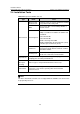
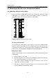
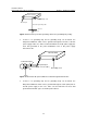
DC power input
Ethernet Switch
RTN
-48V
AC/DC
power box
-48V strip
RTN strip
PGND strip
Ground
Grounding screw
Figure 3-6 Ground a DC-powered Ethernet switch through the RTN wire of a power
cabinet
3.5 Installing Switch Modules
For the procedure for installing cards, power modules, and fan tray, refer to Chapter 5
“Hardware Maintenance”.
3.6 Connecting the Power Cable
3.6.1 Connecting the AC Power Cable
I. PSR320-A power module
Figure 3-7 Connect the AC power cable for the PSR320-A (I)