
H3C S7500E Series Ethernet Switches Installation Manual


Installation Manual
H3C S7500E Series Ethernet Switches Chapter 3 Hardware Installation
3-8
3) Plug the other end into the AC power socket strip, which is connected to the AC
power supply in the equipment room.
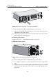
IV. PSR2800-ACV power module
There are two AC power inputs on the PSR2800-ACV power module, one for system
power and the other for PoE power. The connection of the power cable for each power
input is the same as that of the PSR1400-A. For the detailed connection method, refer
to section
3.6.1 III. “PSR1400-A power module” on 3-7.
Note:
Since the busbars used in equipment rooms are typically for 10A power cables, but the
PSR1400-A power module and PSR2800-ACV power module require a 16A power
cable (AC), you need to provide a busbar suitable for 16A power cables. Refer to
Appendix B “AC Power Cables Used in Different Countries or Regions“ for AC power
cable specifications.
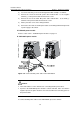
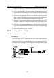
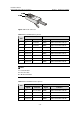
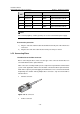
3.6.2 Connecting the DC Power Cables
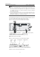
I. PSR320-D power module
Figure 3-10 Connect the DC power cable for the PSR320-D
Caution:
Turn off all switches on the switch before connecting the DC power cables.
To connect the DC power cable for the PSR320-D, proceed as follows:
1) Remove the protection cover from the power module.