
H3C S7500E Series Ethernet Switches Installation Manual


Installation Manual
H3C S7500E Series Ethernet Switches Chapter 3 Hardware Installation
3-9
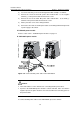
2) Loosen the fastening screw on the wiring terminal with a Phillips screwdriver.
3) Connect the end of the blue DC power cable marked with – to the negative
terminal (–) on the power module and fasten the screw.
4) Connect the end of the black DC power cable marked with + to the RTN (+)
terminal on the power module and fasten the screw.
5) Put the protection cover on the wiring terminals.
6) Connect the other ends of the DC power cables to the wiring terminals that provide
a power supply to the switch.
II. PSR650-D power module
Refer to section 3.6.2 I. “PSR320-D power module” on page 3-8.
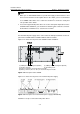
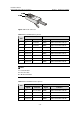
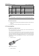
III. PSR1400-D power module
Figure 3-11 Connect the DC power cable for the PSR1400-D
Caution:
z Turn off all switches on the switch before connecting the DC power cables
z If power to the PSR1400-D power module is switch controlled, make sure that the
negative input of the power module is disconnected when disconnecting power to
the power module.
To connect the DC power cables for the PSR1400-D, proceed as follows: