
H3C S7500E Series Ethernet Switches Installation Manual


Installation Manual
H3C S7500E Series Ethernet Switches Chapter 3 Hardware Installation
3-10
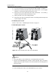
1) Loosen the fastening screws on the protection cover with a Phillips screwdriver
and remove the protection cover. There are two flat washers, one spring washer,
and one fastening nut M6 from inside to outside on each wiring terminal.
2) Loosen the fastening nut on four wiring terminals with a socket wrench M6 and
remove the fastening nut, spring washer and one flat washer in turn.
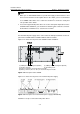
3) Connect the end of the blue DC power cable marked with – to the negative
terminals (-) on the power module and fasten the screws.
4) Connect the end of the black DC power cable marked with + to the RTN (+)
terminals on the power module and fasten the screws.
5) Put the flat washers and spring washer on the wiring terminal in turn and screw up
the fastening nut with the socket wrench M6. Repeat this step for the other three
terminals.
6) Put the protection cover on the wiring terminals and screw up the fastening
screws.
7) Connect the other ends of the DC power cables to the wiring terminals that provide
a power supply to the switch.
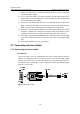
3.6.3 Connecting PoE Power Cables
To provide PoE supply to attached devices, the S7500E series require appropriate PoE
power modules. PoE power modules fall into external and internal types.
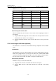
1) The S7502E and the S7503E-S require not only an internal power module for its
own power feed, but also an appropriate external PoE power module,
PSE2500-A3 for example, to provide PoE supply.
2) The S7503E, S7506E, S7506E-V, and S7510E require only internal PoE power
modules, PSR1400-D or PSR2800-ACV for example, for both their own power
feed and PoE supply to attached devices.
z With PSR1400-D modules, an S7503E, S7506E, S7506E-V, or S7510E can
provide a maximum of 6720 W of PoE supply.
z With PSR2800-ACV modules, an S7503E, S7506E, S7506E-V, or S7510E can
provide a maximum of 1400 W of PoE supply.
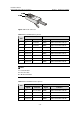
In the case of PSR1400-D power modules, the power cables can be directly used as
the PoE input cables. For how to connect the power cables, refer to section
3.6.2 III.
“
PSR1400-D power module” on page 3-9.
In the case of PSR2800-ACV power modules, you can connect the 16A AC power
cables to the PoE input ends of the power modules for PoE input. For how to connect
the power cables, refer to section
3.6.1 IV. "PSR2800-ACV power module" on page
3-8.