
H3C S7500E Series Ethernet Switches Installation Manual


Installation Manual
H3C S7500E Series Ethernet Switches Chapter 3 Hardware Installation
3-12
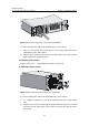
1) Remove the protection cover from the terminals which are used to connect the
external PoE power supply.
2) Use a socket wrench M5 to loosen the fastening nut on the input terminal of the
switch, and a socket wrench M8 to loosen the fastening nut on the output terminal
of the external PoE power supply.
3) Connect the end marked with –48V OT of one delivered DC power cable to the
NEG (-) terminal on the switch and screw up the nut. Connect the other end to the
NEG (-) terminal of the external PoE power supply and screw up the nut.
4) Connect the end marked with GND OT of the other delivered DC power cable to
the RTN (+) terminal on the switch and screw up the nut. Connect the other end to
the RTN (+) terminal of the external PoE power supply and screw up the nut.
5) Connect the end marked with PGND OT of the grounding cable to the grounding
screw of the switch and fasten the screw. Connect the other end to the grounding
strip.
6) Remount the protection cover on the terminals.
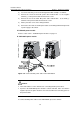
3.7 Connecting Interface Cables
3.7.1 Connecting the Console Cable
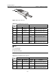
I. Introduction
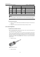
The console cable is an 8-core shielded cable. One end is a crimped RJ-45 connector,
which is to be plugged into the console port. The other end is furnished with a DB-9
female connector. You can select either of them based on your actual requirements to
fit in with the 9-pin serial interface at the configuration terminal. The following figure
shows the console cable.
Figure 3-14 Console cable